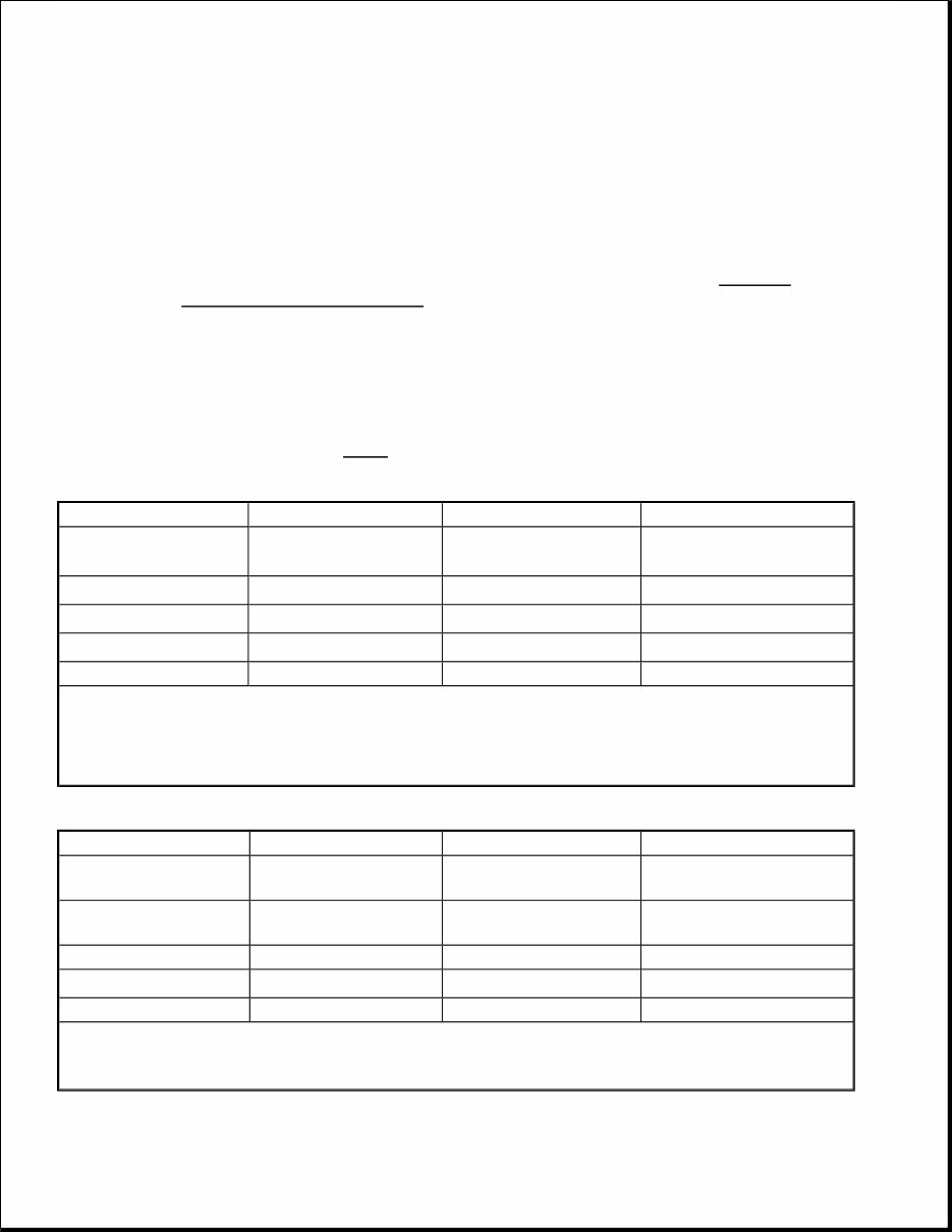
ENGINES 2.3L & 2.4L 5-Cylinder & 2.9L 6-Cylinder ENGINE IDENTIFICATION Engine may be identified by using Vehicle Identification Number (VIN) stamped on a metal pad located near lower left corner of windshield. The sixth and seventh characters are the VIN engine code. Engine Type identification number, located on left side of cylinder block below cylinder head, may be required when ordering replacement parts. See Fig. 1 . 1997 MODEL & ENGINE CODE COVERAGE 1998 MODEL & ENGINE CODE COVERAGE NOTE: For engine repair procedures not covered in this article, see ENGINE OVERHAUL PROCEDURES article in GENERAL INFORMATION. Not all repair information for this engine is not available from manufacturer. Model (Series) Engine Code Engine Type Engine Management 850 (L) 55 (2.4L DOHC) B5254S Motronic 4.3 Or 4.4 (SFI) (1) 850 GLT (L) 56 (2.4L DOHC) B5254T (2) Motronic 4.4 (SFI) 850 R (L) 50 (2.3L DOHC) B5234T4 (3) Motronic 4.4 (SFI) 850 R (L) 58 (2.3L DOHC) B5234T5 (3) Motronic 4.4 (SFI) 960, S90 & V90 (V) 96 (2.9L DOHC) B6304S Motronic 4.4 (SFI) (1) Vehicles with Motronic 4.3 are equipped with an EGR system, vehicles with Motronic 4.4 are not. (2) Low pressure turbo. (3) Standard turbo. Model (Series) Engine Code Engine Type Engine Management C70 (N), S70 (L) & V70 (L) & V70 XC (L) 56 (2.4L DOHC) B5254T (1) Motronic 4.4 (SFI) C70 (N), S70 (L) & V70 (L) x 53 (2.3L DOHC) B5234T3 (2) Motronic 4.4 (SFI) S70 & V70 (L) 55 (2.4L DOHC) B5254S Motronic 4.4 (SFI) V70 (L) 52 (2.3L DOHC) B5234T6 (2) Motronic 4.4 (SFI) S90 & V90 (V) 96 (2.9L DOHC) B6304S Motronic 4.4 (SFI) (1) Low pressure turbo. (2) Standard turbo.
Fig. 1: Identifying Engine Type Location Courtesy of VOLVO CARS OF NORTH AMERICA. ADJUSTMENTS MECHANICAL TIMING BELT TENSIONER For information on 1998 C/S/V 70 models with 5-cylinder engines and mechanical timing belt tensioner, see TIMING BELT REPLACEMENT - 2.3L & 2.4L article. VALVE CLEARANCE ADJUSTMENT Engine is equipped with hydraulic lifters. No valve adjustment is necessary. TROUBLE SHOOTING To trouble shoot engine mechanical components, see ENGINE MECHANICAL in TROUBLE SHOOTING article in GENERAL INFORMATION. REMOVAL & INSTALLATION
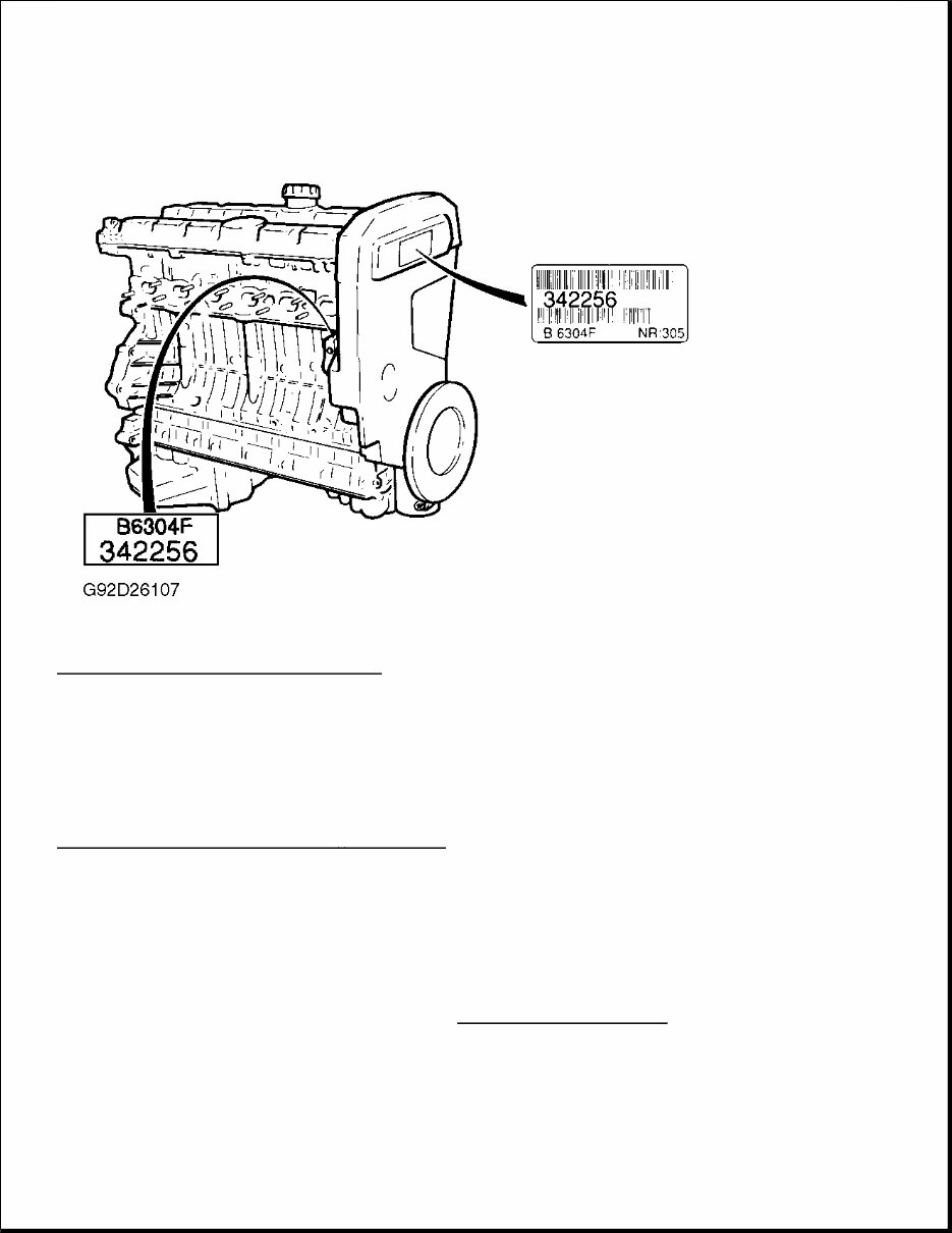
FUEL PRESSURE RELEASE Fuel Pump Pressure Release 1. Unplug fuel pump relay. Start engine and run until engine stalls. Crank engine an additional 3 seconds. 2. Before disconnecting any lines, cover fuel line connector with shop towel to absorb any fuel left in line. With ignition key removed from ignition switch, reconnect fuel pump relay. ENGINE Removal (5-Cylinder) 1. Remove expansion tank cap. Raise and support vehicle. Remove splash guard and air baffle under engine. Drain all coolant by opening drain cocks on cylinder block and radiator. Remove front wheels, steering arm/wheel spindle joints, and nuts securing ball joints to support arms. 2. Remove ABS wire and brake line retaining bracket bolt located on inner fender panel, close to bottom of strut. Remove left axle shaft. See FWD AXLE SHAFTS article in DRIVE AXLES. Disconnect 2 thin, Black hoses from evaporative fuel canister. Remove White vacuum hose from vacuum reservoir. 3. Remove right axle shaft and intermediate bearing cap. Carefully place components on steering servo pipes. Remove 2 right engine mounting bolts. Loosen wheel arch liner to allow access to mounting. Remove torque arm in gearbox. See Fig. 2 . Install Sealing Plugs (5488) in axle shaft holes. NOTE: For reassembly reference, label all electrical connectors, vacuum hoses and fuel lines before removal. Also place mating marks on other major assemblies before removal. Hood removal is not necessary, as hood opens to horizontal position. Removal and installation information for turbocharger is not available from manufacturer.
Fig. 2: Removing Drive Shaft, Engine Mount Bolt & Torque Arm (5 - Cylinder) Courtesy of VOLVO CARS OF NORTH AMERICA. 4. Remove front exhaust pipe nuts and springs. Remove front exhaust pipe bolts. Disconnect speedometer. Remove engine mounting shield bolt. Lower vehicle. 5. Remove battery, battery self, and fresh air hose between air intake and air cleaner housing. Disconnect MAF sensor connector and primary lead between distributor and coil. Remove throttle pulley cover. If equipped with cruise control, disconnect all necessary electrical wiring and vacuum hose. 6. Disconnect intake hose at throttle body and idle air control valve hose. Disconnect vacuum hose and crankcase ventilation hose from intake hose. Disconnect vacuum hoses and connector from solenoid valve. Disconnect heater hose. Remove air cleaner housing. Disconnect throttle cable from throttle pulley. Remove torque arm. 7. Disconnect 2 heater hoses at firewall, brake servo hose, and 2 HO2S connectors. Remove upper nut on rear engine mount. Disconnect gear selector cables from mounting bracket on transmission. Disconnect rubber-mounted section of cable bracket. On automatic transmission equipped vehicles, disconnect 2 oil cooler hoses. On manual transmission equipped vehicles, remove clutch slave cylinder retaining ring. Remove slave cylinder from transmission. 8. On all vehicles, disconnect negative battery cable. Disconnect lower radiator hose at radiator. Loosen and move air cleaner mounting bracket aside. Remove rubber mount from air cleaner bracket. On manual transmission equipped vehicles, remove clutch slave cylinder through front hole in air cleaner bracket and place aside. On all vehicles, place air cleaner bracket aside.
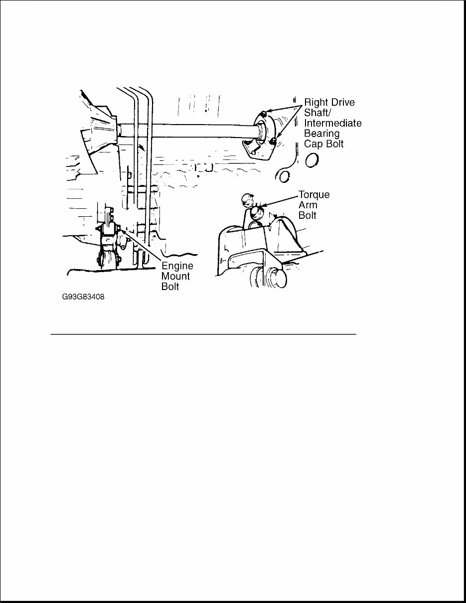
9. Remove electric cooling fan relays from fan shroud. Disconnect connectors and place wiring aside. Remove 2 control module box cooling air ducts. Remove 4 fan shroud screws from radiator. Use a piece of plywood to protect radiator and slide fan housing back slightly and remove air intakes. Remove fan. 10. Remove 2 long mounting bolts in A/C compressor. Leave compressor in position until removing engine. Remove front engine mounting pad nut and cable duct bracket mounting bolts. Remove intake manifold and starter support brackets. 11. Disconnect upper radiator hose from thermostat housing. Remove coolant hose between expansion tank and thermostat housing. Remove expansion tank lower hose from fitting on engine. Remove drive belt. Disconnect temperature sensor wiring from bracket on servo pump. Remove 6 servo pump bolts. Leave servo pump in position at this time. 12. Remove protective cover over fuel distribution manifold. Remove upper and lower fuel pipe clips. Remove fuel distribution manifold bolts. Disconnect braided ground lead from engine. Secure injectors with 5 Holders (5465). Lift and place fuel distribution manifold (including injectors) aside. Remove engine wiring harness. See Fig. 3 .
Fig. 3: Removing Engine Wiring Harness (5 - Cylinder) Courtesy of VOLVO CARS OF NORTH AMERICA. 13. Remove spark plug cover and attach Lifting Lugs (5459 and 5464) to engine. Lift servo pump and place aside. Remove A/C compressor and place on sub-frame. Lift out engine and transmission using Lifting Yokes (2810 and 5428). Removal (6-Cylinder) 1. Place hood in vertical position. Disconnect battery. Remove ground lead connection to body at top side member. Remove clip on side member. Remove battery. Remove auxiliary drive belt. Remove cooling fan and drain coolant.
2. Disconnect upper and lower coolant hoses from engine. Disconnect expansion tank hose from radiator and return pipe. Disconnect cooling lines from radiator. 3. Remove top nut from both left and right engine mounts. Remove air mass meter and intake hose. Disconnect and remove large and small crankcase ventilation hoses, idling hose and idling valve lead. 4. Remove 2 EVAP valve hoses at intake manifold. Remove air mass meter connector, air preheater hose and throttle pulley cover. Remove 3 bolts at front of servo pump and 2 at rear of servo pump. Remove servo pump. 5. Disconnect fuel return line at regulator. Remove fuel line at bulkhead. Remove throttle cable. Remove cruise control vacuum hose. Remove fuel line snap catches. Remove engine wiring harness cover and disconnect connector. Remove harness duct mounting nuts. 6. Disconnect 2 cooling hoses from firewall. Remove 2 ECC hoses at intake manifold. Remove camshaft sensor, timing pick-up and brake servo vacuum line. To support engine, use 2 Support Rails (5033), Lifting Beam (5006), Lifting Hook (5115) and Lifting Yoke (5428). Attach Lifting Lug (5429) to rear of engine. Support engine. 7. Remove splash guard and air baffle under engine. Loosen 2 radiator mounting bolts. Drain engine oil. Disconnect oil thermostat hoses at thermostat in cylinder block. Remove 2 air conditioner compressor mounting bolts and disconnect electrical connector. Remove compressor and lay aside. 8. Loosen exhaust pipe flanges at manifold. Remove lower section of air preheater pipe. Remove exhaust pipe shield. Remove oil cooler lines at transmission. Disconnect gear selector lever from transmission. 9. Disconnect oxygen sensor wiring. Mark propeller shaft for reassembly reference. Disconnect propeller shaft and remove transmission support member. Place jack under transmission and remove all lifting tools. Remove radiator attaching bolts. Lift out radiator and transmission fluid cooling lines. 10. Using Lifting Tool (2810), lift engine from vehicle. Remove jack from under transmission. Installation (5-Cylinder & 6-Cylinder) 1. Attach Lifting Lug (5429) to rear of engine. Using Lifting Yoke (5428) and Lifting Tool (2810), lower engine and transmission into position. Guide engine mountings into position and tighten top nuts to 37 ft. lbs. (50 N.m). 2. Support transmission with floor jack, and remove lifting yoke from engine. Using 2 Support Rails (5033), Lifting Beam (5006) and Lifting Hook (5115), support rear of engine. Remove jack under transmission. Using Transmission Lifting Fixture (5972), raise transmission. Install transmission support member. Tighten bolted joints between support member and side members. Tighten transmission bump stop nut to specification. See TORQUE SPECIFICATIONS . 3. Install control rod and reaction arm to lever mounting. Install locking clip. Install oxygen sensor and reconnect electrical connector. Using Socket (5244), tighten front and rear couplings. Ensure "O" ring is okay and install air preheater pipe to exhaust pipe. 4. Install air conditioning compressor to mounting. Reconnect oil cooler lines. Tighten fittings to 26 ft. lbs. (35 N.m). Remove lifting tools. 5. Reinstall coolant hoses to firewall. Install timing pick-up and camshaft sensor connectors. Reconnect engine connector to wiring harness connector on left wheel housing. Reconnect relay and install wiring duct mounting nuts. Install harness connector cover. 6. Install fuel hoses, cruise control vacuum hose, ECC vacuum hoses, brake servo vacuum hose, throttle cable and throttle pulley cover. Install air mass meter and intake hose. Reconnect idling valve hose and
connector. Reconnect oil trap hoses. Reconnect 2 EVAP vacuum hoses. 7. Install servo pump and drive belt. Install radiator and radiator hoses, expansion tank hoses, and transmission oil cooler lines. Tighten cooling line fittings to 26 ft. lbs. (35 N.m). Install cooling fan. Install battery and reconnect positive cable. 8. Jack up vehicle and reconnect cooling lines to transmission. Tighten fittings to 26 ft. lbs. (35 N.m). Install exhaust pipe and heat shield. Install radiator mounting bolts, air baffle under radiator, and splash guard under engine. Fill engine with oil and cooling system. Connect negative battery cable. Start engine, and check for leaks. INTAKE MANIFOLD Removal & Installation (6-Cylinder) 1. Remove the outer section of the intake manifold. Remove the Mass Air Flow (MAF) sensor with the inlet hose. Disconnect battery negative lead. Disconnect connector at the MAF sensor. See Fig. 4 . Remove the Idle Air Control (IAC) valve electrical terminal and air hose. Remove flame trap casing (bayonet connector). Remove inlet hose. Fig. 4: Locating MAF Sensor Connector Courtesy of VOLVO CARS OF NORTH AMERICA. NOTE: Information is not available for 5-cylinder engines.
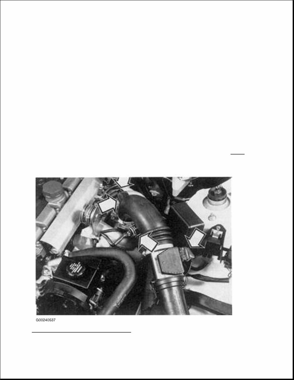
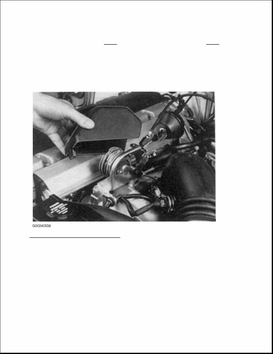
2. Remove throttle pulley cover. See Fig. 5 . Remove the following components. See Fig. 6 . Throttle switch electrical terminal Throttle cable Cruise control vacuum reservoir Cable holder at throttle pulley 2 vacuum hoses at throttle body Fig. 5: Removing Throttle Pulley Cover Courtesy of VOLVO CARS OF NORTH AMERICA.
Get your hands on the 2004 Volvo C70 Service & Repair Manual, a comprehensive guide packed with detailed instructions and procedures specifically for your Volvo C70. Whether you're a professional mechanic or a DIY enthusiast, this manual is an invaluable resource to effectively diagnose and repair your vehicle.
The manual provides precise technical data, clear diagrams, a complete list of car parts, and high-quality images designed to help even novice mechanics follow easy-to-understand, step-by-step instructions. It also includes a thorough list of accessories to boost your engine's performance.
Inside, you’ll find factory-detailed instructions including illustrations, wiring schematics, and diagrams covering a wide range of topics such as maintenance, engine performance, control systems, mechanical repairs, fuel service specifications, and much more.
Compatible with multiple operating systems including Windows Vista (32 and 64 bit), XP, ME, 98, NT, 2000, and Mac, this printable manual allows you to easily print only the pages and diagrams needed at the time, making it convenient to have the information on hand wherever you are.
By handling your own repairs with this manual, you save both time and money while gaining in-depth knowledge about your 2004 Volvo C70. Stay informed and confident with clear, accessible information that reduces the risk of damage or loss.
This manual covers a full range of models and repairs from A-Z, providing vehicle-specific insights commonly used by dealership technicians to maintain, service, diagnose, and repair vehicles. It is available in English and is also accessible in Russian for added convenience.
Maintenance
Engine
Control System
Mechanical
Fuel Service Specifications
Emission Control
Intake Exhaust Cooling
Lube
Ignition Starting Charging
Auto Transmission Clutch
Manual Transmission
Transfer Propeller Shaft
Drive Shaft
Differential
Axle Suspension
Tire & Wheel
Brake Control
Brake
Parking Brake
Steering Column
Power Steering
Air Condition
Suppl Restraint System
Seat Belt
Engine Immobilizer
Cruise Control
Wiper & Washer
Door Lock
Meter Audio/Visual
Horn
Windshield/Glass Mirror
Instrument Panel
Seat
Engine Hood/ Door
Exterior & Interior
Electrical
Multiplex/ Can Communication
And much more...
This manual is your go-to resource for all your 2004 Volvo C70 repair needs, providing the knowledge and confidence to tackle any issues that arise.