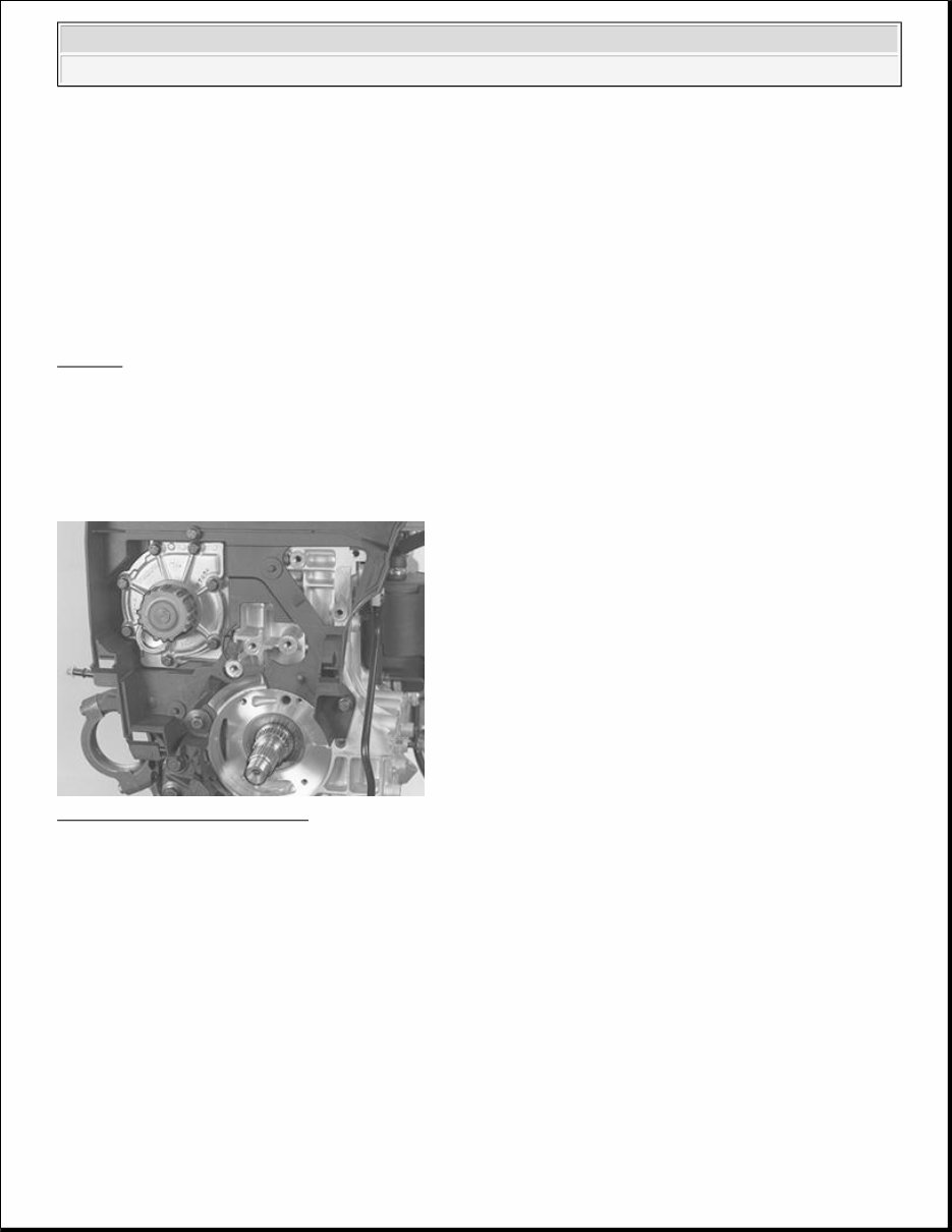
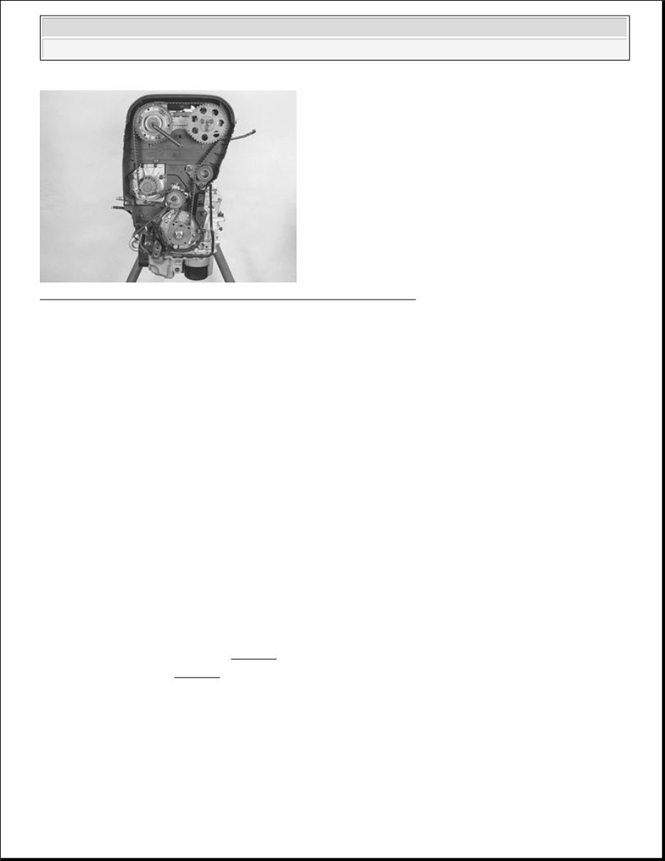
ENGINE Engine - Overhaul Instructions (Convertible) ASSEMBLING ENGINE (B5234T3; B5254T; 1998-1999) ASSEMBLING BELT DRIVE Special tools: 9995747 Installing the water pump Fig. 1: Identifying Water Pump Courtesy of VOLVO CARS OF NORTH AMERICA. Install the rear timing cover. Screw into place at the three mounting points. Install the water pump with a new gasket . Apply thread sealant, P/N 11-61 056, to all the screws for the water pump. Tighten crosswise. Installing the oil pump NOTE: As the illustrations in this service information are used for different model years and / or models, some variation may occur. However, the essential information in the illustrations is always correct. 2003 Volvo C70 ENGINE Engine - Overhaul Instructions (Convertible) 2003 Volvo C70 ENGINE Engine - Overhaul Instructions (Convertible)
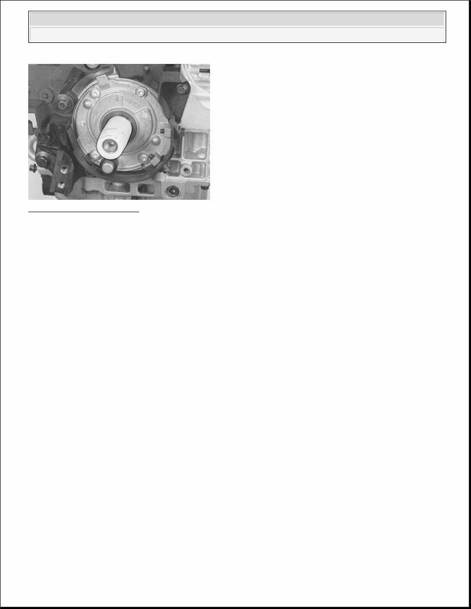
Fig. 2: Install The Oil Pump Courtesy of VOLVO CARS OF NORTH AMERICA. Use a new gasket and a new O-ring around the oil pump housing. Screw sliding sleeve 9995747 into place at the front of the crankshaft journal. Press in the pump over the sliding sleeve. Apply thread sealant, P/N 11-61 56, to all the screws for the oil pump. Install the screws as a guide. Carefully tap in the oil pump with a rubber mallet. Tighten the oil pump crosswise to 10 Nm . Remove sliding sleeve 999 5747 . Installing the crankshaft timing gear pulley 2003 Volvo C70 ENGINE Engine - Overhaul Instructions (Convertible)
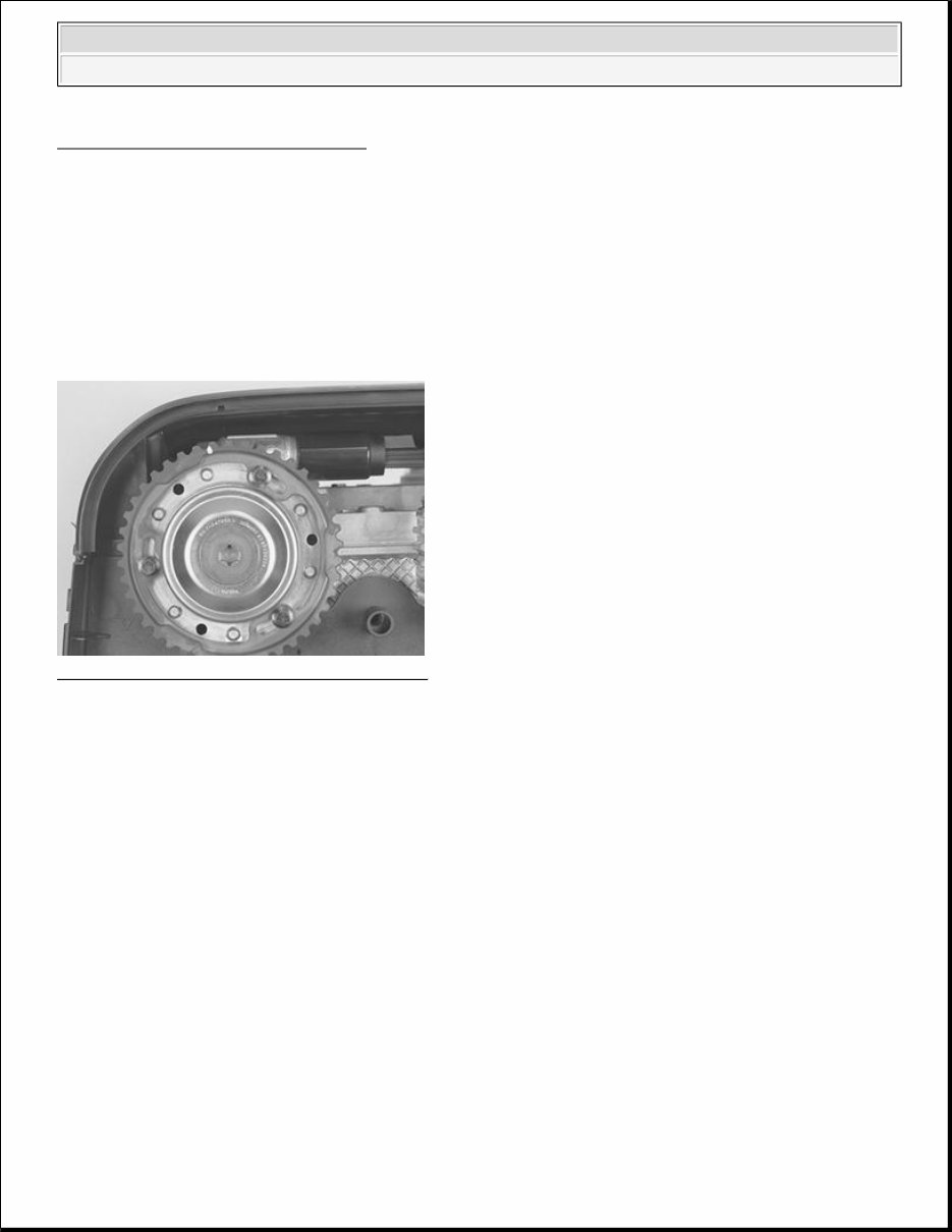
Fig. 3: Crankshaft Timing Gear Pulley Courtesy of VOLVO CARS OF NORTH AMERICA. Carefully tap in the timing gear pulley with a rubber mallet. Installing the idler pulley and belt tensioner NOTE: The timing gear pulley can only be installed in one position on the crankshaft journal splines (see the illustration). 2003 Volvo C70 ENGINE Engine - Overhaul Instructions (Convertible)
Fig. 4: Idler Pulley And Belt Tensioner Courtesy of VOLVO CARS OF NORTH AMERICA. Install the idler pulley. Tighten. Install the belt tensioner and the center screw so that the fork on the tensioner is centered over the cylinder block rib. Do not tighten. Install the fuel delivery line. Installing the timing gear pulley for the camshafts Fig. 5: Identifying Variable Valve Timing Unit Courtesy of VOLVO CARS OF NORTH AMERICA. Timing gear pulleys with variable valve timing unit Slacken off, but do not remove, the screws which secure the timing gear pulley to the variable valve timing unit. Press the variable valve timing unit and timing gear pulley onto the camshaft. Install the center screw which secures the variable valve timing unit to the camshaft. Do not tighten. Position the upper timing cover. Turn the timing gear pulley clockwise until the screws at the oval holes are in their respective limit positions. Hold the variable valve timing unit. Turn clockwise until the timing gear pulley marking is 1 cog before the marking on the upper timing cover. Check that the timing gear pulley is still in the limit position in the oval holes. Tighten the center screw for the variable valve timing unit to 120 Nm . 2003 Volvo C70 ENGINE Engine - Overhaul Instructions (Convertible)
Install the center plug. Tighten to 35 Nm . Timing gear pulleys without variable valve timing units Install the timing gear pulley on the camshaft with two screws. Do not tighten. Check that the markings on the timing gear pulley and the upper timing cover correspond. Installing the timing belt Fig. 6: Turning Variable Valve Timing Unit Using Torx Wrench Courtesy of VOLVO CARS OF NORTH AMERICA. Tighten the center screw on the timing belt tensioner to 5 Nm . Turn the variable valve timing unit clockwise until stop. Use a Tx 55 torx wrench applied at the center plug. Hold the variable valve timing unit secure in the limit position. Install the timing belt. Check that the markings on the timing gear pulleys and the upper timing cover correspond. NOTE: Check that the variable valve timing unit does not rotate when tightening. NOTE: Adjust the timing gear pulleys so that the screws are not at a limit position in the oval holes. 2003 Volvo C70 ENGINE Engine - Overhaul Instructions (Convertible)
Fig. 7: Identifying Timing Belt, Tensioner, And Timing Gear Pulley Courtesy of VOLVO CARS OF NORTH AMERICA. Tighten the timing belt Turn the eccentric on the tensioner counter-clockwise until the tensioner indicator reaches its limit position. Ensure that the center screw does not rotate. Tighten the three screws securing the timing gear pulley to the variable valve timing unit. Tighten to 10 Nm . Install the third screw at the timing gear pulley without variable valve timing. Tighten the screws to 20 Nm . Turn the eccentric back (clockwise) so that the indicator reaches the marked position in the center of the window. Remember to hold the center screw secure at the same time. Secure the eccentric. Tighten the center screw to 20 Nm . Check that the indicator is in the correct position. Remove the camshaft adjustment tools 9995451 the crankshaft stop 9995452 . Install the plug with a new blind cover plug . Tighten to 40 Nm . Check Press the toothed belt to check that the indicator on the tensioner moves easily. NOTE: The variable valve timing unit must not be released from the limit position until after the timing gear pulleys have been tightened. 2003 Volvo C70 ENGINE Engine - Overhaul Instructions (Convertible)
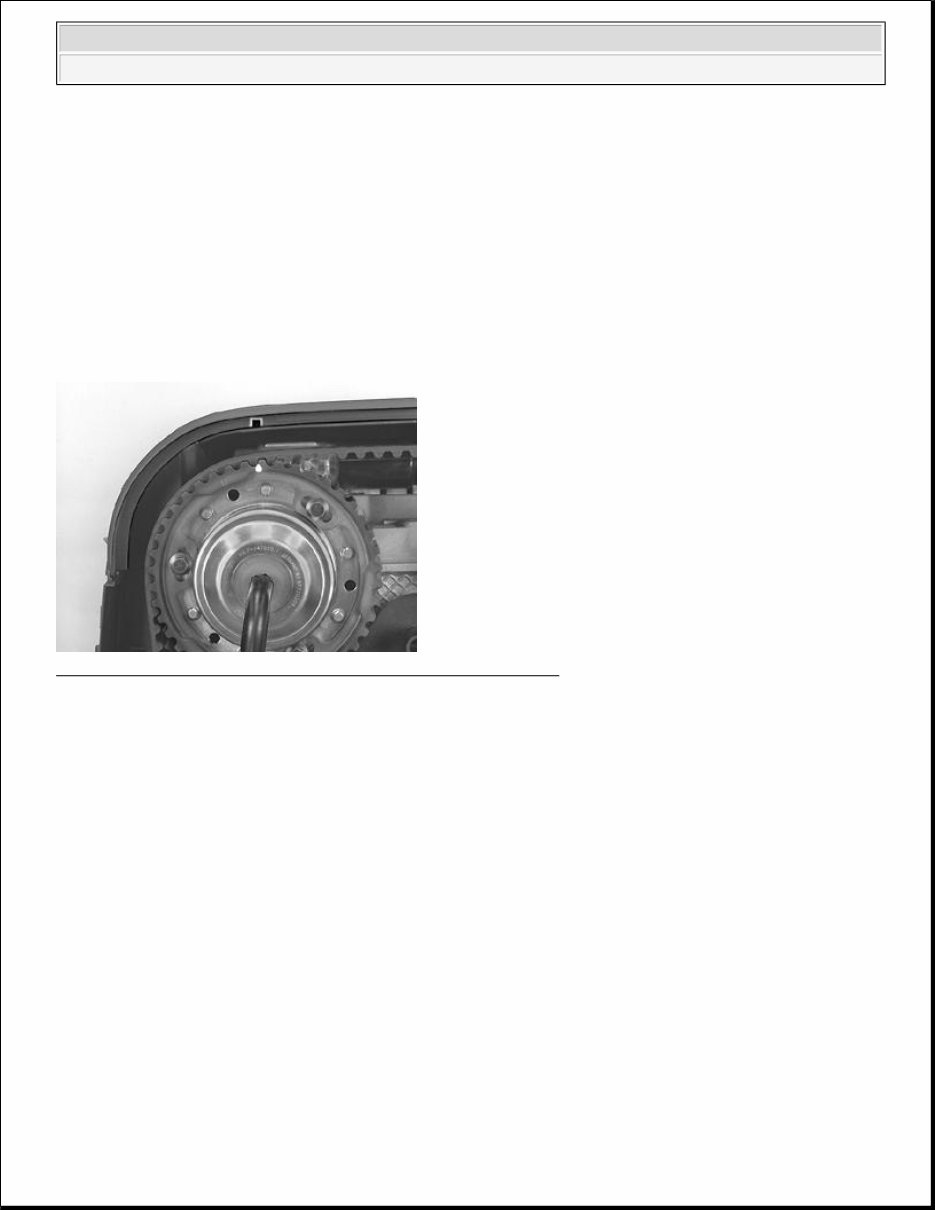
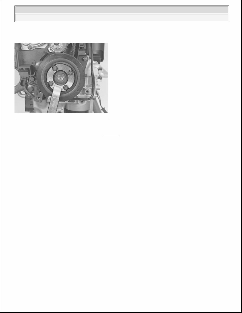
Installing the vibration damper Fig. 8: Removing/Installing Vibration Damper Courtesy of VOLVO CARS OF NORTH AMERICA. Install the vibration damper. Use counterhold 9995433 . Tighten the center nut. Tighten to 180 Nm . Remove counterhold 999 5433. Tighten the four screws. Tighten to 25 Nm . Angle-tighten 30° . Check 2003 Volvo C70 ENGINE Engine - Overhaul Instructions (Convertible)
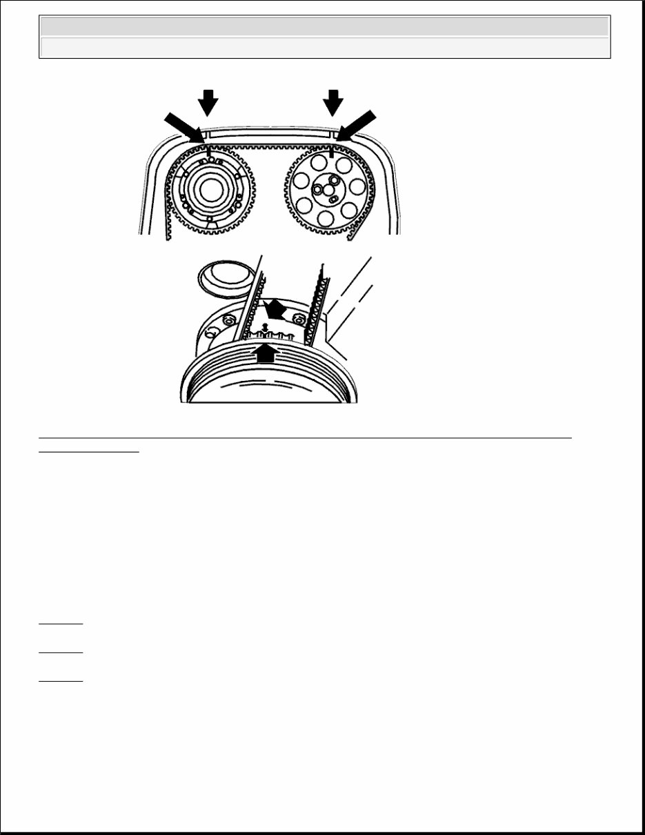
Fig. 9: Identifying Markings On Crankshaft Belt Pulley, Timing Belt Pulley, Oil Pump, And Upper Timing Belt Cover Courtesy of VOLVO CARS OF NORTH AMERICA. Turn the crankshaft two turns. Check that the markings on the crankshaft and camshaft timing gear pulley correspond with the marking on the upper timing cover and on the oil pump. CRANK MECHANISM, ASSEMBLING Special tools: 9512767 9991801 9995676 NOTE: As the illustrations in this service information are used for different model years and / or models, some variation may occur. However, the essential information in the illustrations is always correct. 2003 Volvo C70 ENGINE Engine - Overhaul Instructions (Convertible)
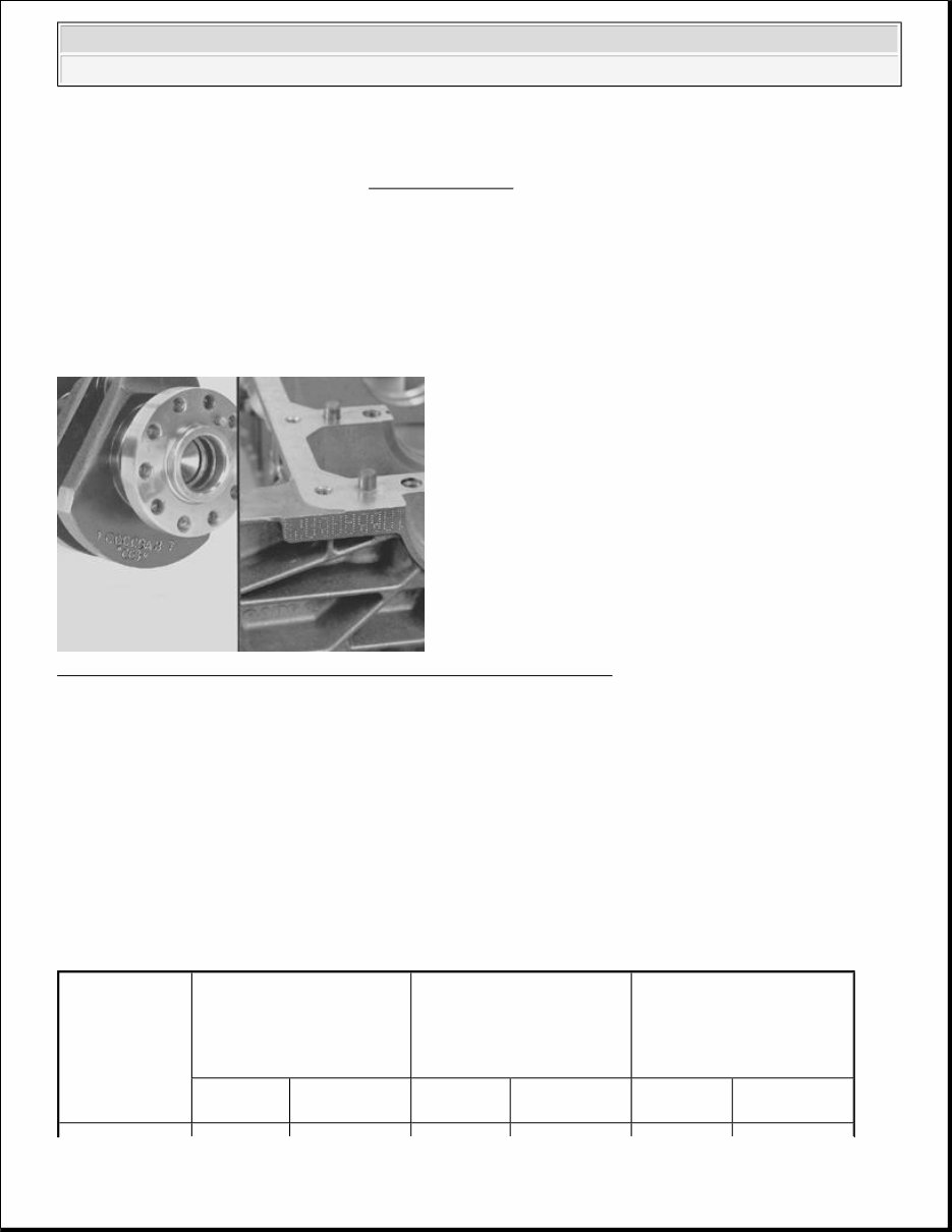
Tightening torque For tightening torques not in the text, see Tightening torque . Cleaning Ensure that the all components are completely clean. Blow clean the oil ducts in the block, intermediate section and oil pan. Classification of main bearings Fig. 10: Identifying Classification Marking On Block And Crankshaft Courtesy of VOLVO CARS OF NORTH AMERICA. Wipe clean the bearing recesses in the block and the intermediate section. Check that the components are clean and undamaged. Check the classification of the block and crankshaft. The classification marking is at the rear edge of the block and the crankshaft. The classification is read from digits 1 to 7. The first letter after digit 1 is the classification of main bearing 1. The bearing positions are numbered starting at the front of the engine. Selecting bearings Cylinder block classification / Crankshaft classification A small diameter B medium- diameter C large diameter block intermediate section block intermediate section block intermediate section 2003 Volvo C70 ENGINE Engine - Overhaul Instructions (Convertible)
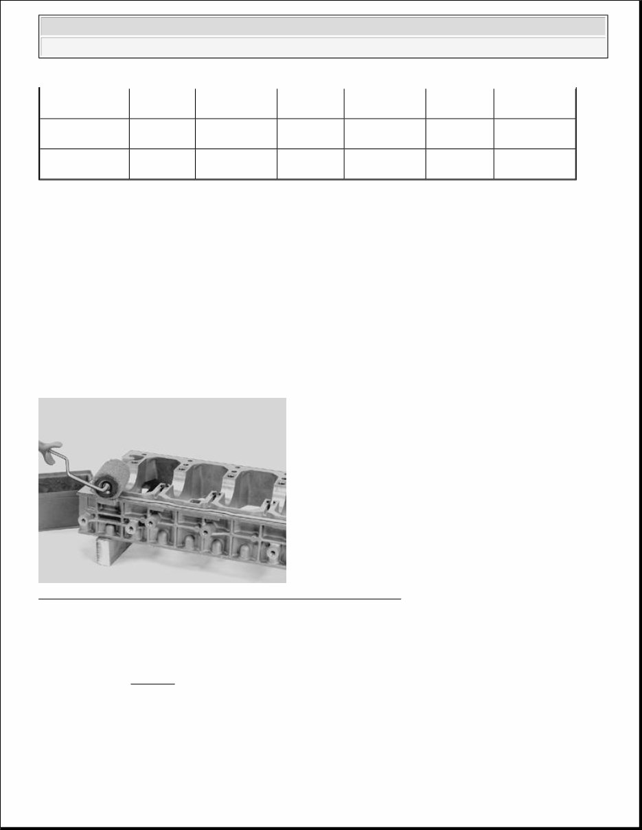
Install the main bearings in the cylinder block and the intermediate section. See the table. The axial bearing is positioned at bearing recess 5. For example: The marking on the block at bearing recess 1 is B. The marking on the crankshaft at the corresponding bearing recess is C. Therefore the bearing in the block is marked red and the bearing in the intermediate section is marked yellow. Intermediate section Fig. 11: Applying Liquid Gasket 11 61 059 On Intermediate Section Courtesy of VOLVO CARS OF NORTH AMERICA. Wipe the surfaces dry. Apply liquid gasket 11 61 059 to the intermediate section. The surface must be completely covered without any excess. Use roller 9512767 Thoroughly lubricate all the bearing shells and the surface of the axial bearing. Tightening intermediate section A small yellow medium yellow medium yellow medium blue thick blue thick blue thick B medium red thin yellow medium yellow medium yellow medium yellow medium blue thick C large red thin red thin red thin yellow medium yellow medium yellow medium NOTE: The thickest of the bearing caps must always be installed in the intermediate section. This is keep the center line as straight as possible. 2003 Volvo C70 ENGINE Engine - Overhaul Instructions (Convertible)
If you are in need of a repair manual for your 2003 Volvo C70, look no further. Our accessible repair manual is a cost-effective and convenient alternative to traditional paper manuals. Whether you are a professional mechanic or a DIY enthusiast, this manual covers all the essential service and repair information for the Volvo C70.
In the past, obtaining a traditional service manual in book format was not only expensive but also less convenient. Our repair manual provides the same valuable information at a fraction of the cost and in a more accessible format.
Whether you are tackling brake repairs, suspension component replacements, engine troubleshooting, or standard maintenance tasks, this repair manual for the Volvo C70 has got you covered. It includes comprehensive service information for brakes, engine, suspension, steering, drivetrain, electrical systems, heating, air conditioning, and more.
By utilizing this manual, you can save a significant amount of money on vehicle repairs. Professional mechanics often charge high fees for their services, making a DIY approach with the assistance of our 2003 Volvo C70 repair manual a cost-effective solution.
Our manual is designed for ease of use and is compatible with Windows, Mac computers, smartphones, and tablets, ensuring accessibility across various devices.