19-1 Parts of cooling system, removing and installing Note: When the engine is warm, the cooling system is under pressure. If necessary release pressure before beginning repair work. Hoses are secured with spring-type clips. In cases of repair use spring-type clips. VAG 1921 pliers are recommended when installing spring-type clips. Perform cooling system leakage check with cooling system tester VAG 1274 and adapter 1274/3. Parts of cooling system body side Page 19 - 2 . Parts of cooling system engine side Page 19 - 10 . Coolant hose connection diagram Page 19 - 14 . Draining and filling with coolant Page 19 - 16 .
Coolant mixture ratios Page 19 - 16 , draining and filling with coolant. Checking thermo switch and coolant circulation pump or continued coolant circulation pump Page 19 - 27 .
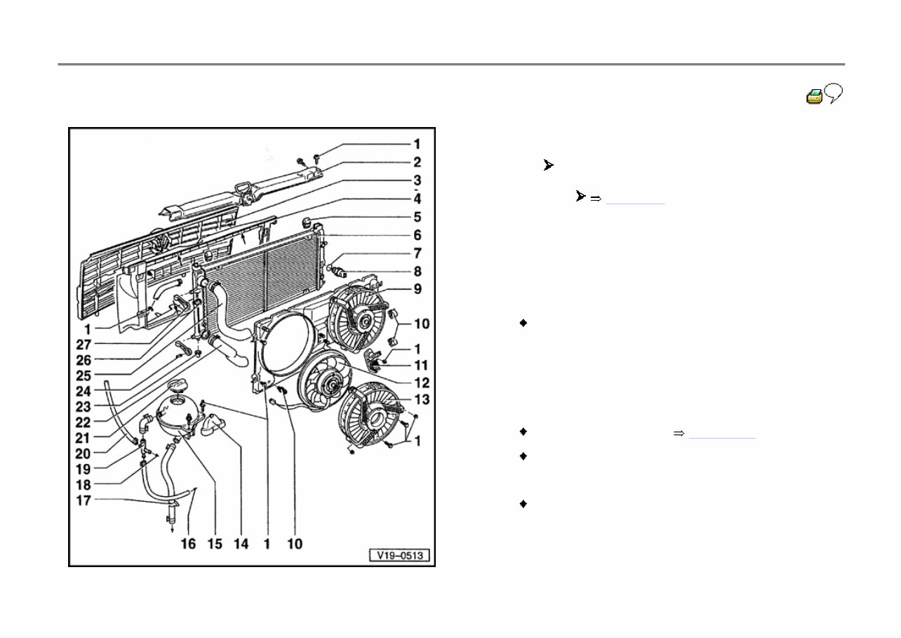
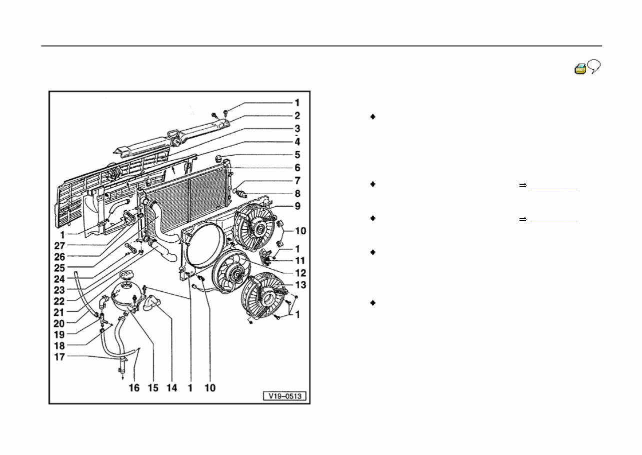
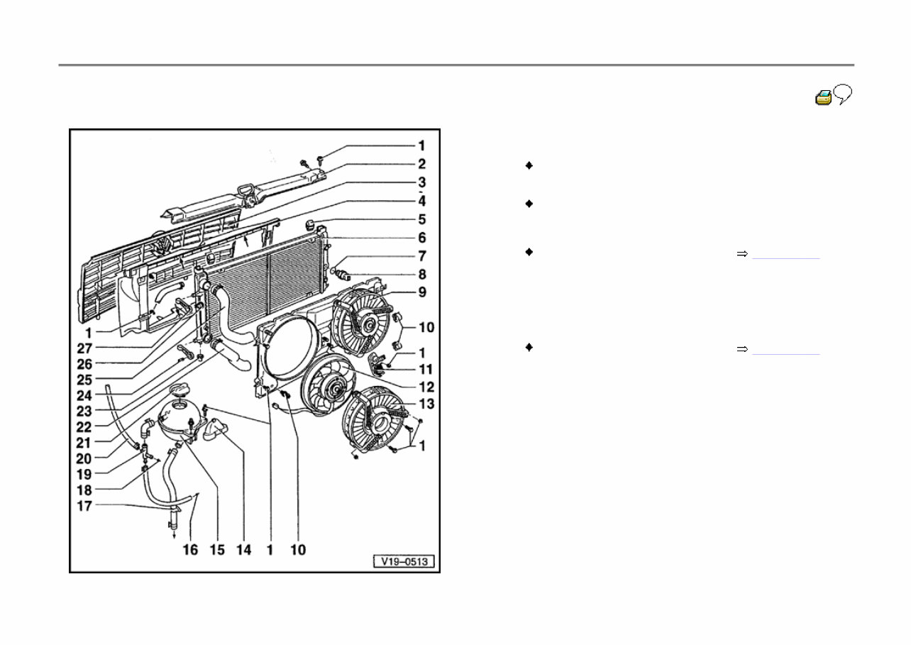
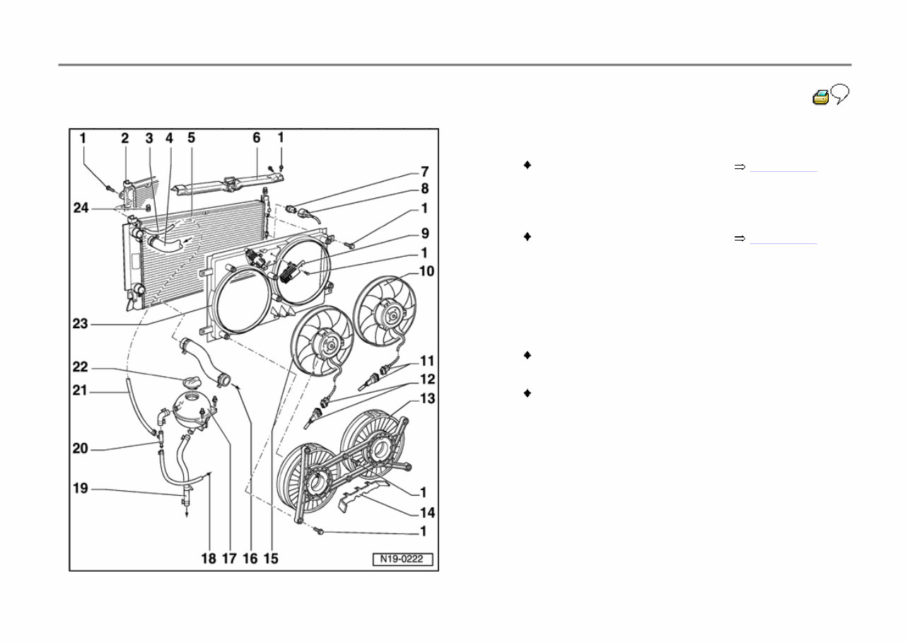
19-2 Parts of cooling system, body side Vehicles 12.95 Vehicles 01.96 Page 19 - 6 1 - 10 Nm 2 - Lock carrier 3 - Radiator grille 4 - Air ducting Secured at radiator: Vertically 4 screws, horizontally 4 rivets or 4 screws - arrows- 5 - Securing rubber 6 - Radiator Removing and installing Page 19 - 22 After replacing, replace coolant 7 - Seal Always replace
19-3 8 - Coolant fan control (FC) thermal switch -F18-, 35 Nm Switching temperatures: 1st speed on: 84 - 89 C off: 76 - 83 C 2nd speed on: 90 - 95 C off: 82 - 89 C 9 - Radiator cowling With electric fan and adjustable shut-off ring (only vehicles with optional equipment) 10 - Cable clip 11 - Adjusting device Only vehicles with optional equipment Checking: Engine cold (coolant temperature below 25 C) shut- off ring item - 13 - closed 12 - Radiator fan
19-4 13 - Shut-off ring Only vehicles with optional equipment 14 - Cover 15 - Expansion tank 16 - To cylinder head Coolant hose connection diagram Page 19 - 14 17 - To coolant line Coolant hose connection diagram Page 19 - 14 18 - To heat exchanger Only vehicles with optional equipment 19 - Junction piece 20 - Coolant breather hose To top of radiator
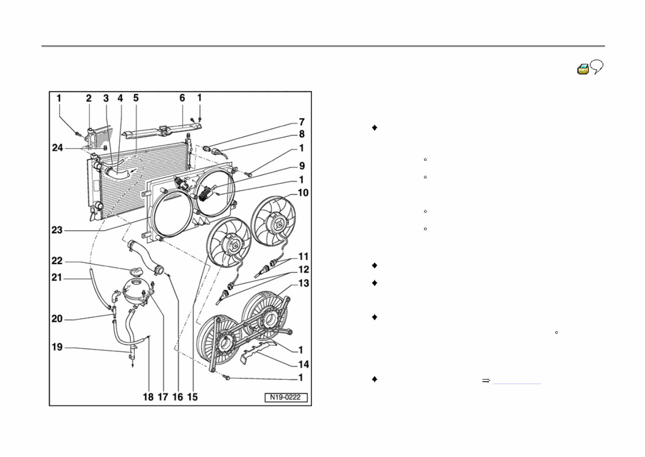
19-7 7 - Coolant fan control (FC) thermal switch -F18-, 35 Nm Switching temperatures: 1st speed on: 84 - 89 C off: 76 - 83 C 2nd speed on: 90 - 95 C off: 82 - 89 C 8 - Connector Black, 3 pin For radiator fan thermo switch 9 - Adjusting device Checking: Engine cold (coolant temperature below 25 C) shut- off ring item - 13 - closed 10 - Right coolant fan -V35- Removing and installing Page 19 - 22
19-8 11 - 2 pin connector Black For right coolant fan -V35- 12 - 2 pin connector Black For left coolant fan -V7- 13 - Shut-off ring 14 - Cable guide 15 - Left coolant fan -V7- Removing and installing Page 19 - 22
19-9 16 - Lower coolant hose Coolant hose connection diagram Page 19 - 14 17 - Expansion tank 18 - To cylinder head Coolant hose connection diagram Page 19 - 14 19 - To coolant line 20 - Junction piece 21 - Coolant breather hose 22 - Cap Check with cooling system tester VAG 1274 and adapter VAG 1274/4 Test pressure 1.3 - 1.5 bar 23 - Air intake ducting 24 - Securing rubber
The 1995 Volkswagen Eurovan Service & Repair Manual is a comprehensive guide suitable for professional mechanics and DIY enthusiasts. It is specifically designed to assist in the maintenance and repair of the 1995 Volkswagen Eurovan models.
It covers a wide range of topics, including electrical systems, engine repair, transmission maintenance, and much more. With detailed instructions, diagrams, and illustrations, this manual provides a step-by-step approach to ensure that repairs are done correctly and efficiently.
Whether you are a seasoned mechanic or a Volkswagen Eurovan owner looking to save on repair costs, this manual is an essential resource. It provides all the necessary information and guidance to keep your Eurovan running smoothly.
This manual is suitable for the following 1995 Volkswagen Eurovan models:
Eurovan GL 2.5 L5
Eurovan GLS 2.5 L5
Eurovan Camper 2.5 L5
Eurovan Campmobile 2.5 L5
Eurovan MV 2.5 L5
Invest in the 1995 Volkswagen Eurovan Service & Repair Manual and gain the confidence to tackle any maintenance or repair task with ease.