HVAC Air Conditioning 87 AIR CONDITIONING GENERAL INFORMATION A/C COMPRESSOR REPLACEMENT INFORMATION -- After installing a new A/C compressor or fresh refrigerant oil has been filled into compressor (for example, after blowing through the A/C system), turn ribbed belt pulley of A/C compressor 10 rotations by hand before starting the engine. This prevents damage to the A/C compressor. NOTE: Start the engine only after assembling the refrigerant circuit. Only start the engine when the refrigerant circuit is filled. The A/C compressor is always driven by the ribbed belt pulley/torsion elastic clutch. It does not have a magnetic clutch. If an A/C compressor locks-up the overload protection for the A/C compressor shaft is triggered. An indication that the A/C compressor is blocked is deformations/bumps on the ribbed belt pulley/overload protection in front of the A/C compressor, but these are not always easy to detect. Another indicator is abraded rubber material in the area of the ribbed belt pulley / overload protection. The A/C compressor is equipped with a protected oil supply, this prevents A/C compressor damage in the event that the system is empty. This means that approximately 40 to 50 cm 3 of refrigerant oil remains in the A/C compressor. The engine may only be started when the refrigerant circuit is installed correctly. For example; if the refrigerant lines are not connected to A/C compressor, when the engine is running the A/C compressor may heat up (via internal heat generation) so much that the A/C compressor will be damaged. A/C Compressor Regulator Valve -N280- is not activated when the refrigerant circuit is empty and the A/C compressor idles with the engine. If it is necessary to start the engine with a discharged refrigerant circuit: Refrigerant circuit must be fully assembled. At least 1/4 of the prescribed refrigerant oil must be in the A/C compressor. HVAC Air Conditioning
-- Pay attention to the following when starting the engine for the first time after filling the refrigerant circuit: -- Start engine with A/C compressor switched off (ECON or AC) and wait until the idling speed stabilizes. -- Open the instrument panel vents. -- Select the temperature setting Lo on the Front A/C display control head -E87-. -- Switch the A/C compressor on (AUTO or AC ON) and let it run at least 5 minutes at less than 1, 500 RPM with the engine running. A/C REPAIRS AND HANDLING REFRIGERANTS Additional Information A data plate on the lock carrier indicates the refrigerant used and capacity. CLIMATRONIC A/C SYSTEM WITH AUTOMATIC CONTROL Do not rev engine higher than 2000 rpm. The engine should run less than 10 minutes and the A/C system should be switched off. NOTE: Information on repairs in vehicles with a climate control system and on handling refrigerant can be found in the repair information. Refer to General Information . Information on tools for repairs in vehicles with climate control system can be found in repair information. Refer to Special Tools . It is no longer necessary to replace the dryer bag each time the refrigerant circuit is opened under certain conditions. Refer to Removal and Installation . CAUTION: Do not bend or kink A/C lines excessively. There is a foil inside the refrigerant lines that can be destroyed. Refrigerant lines must not be bent beyond a radius equal to or less than R = 100 mm. NOTE: The vehicle has a Climatronic with 2-zone right/left temperature control or 4- zone right/left, front/rear temperature control. Pressing the button "AUTO" will reverse all settings which deviate from the automatic operation. HVAC Air Conditioning
CLIMATRONIC TEMPERATURE UNITS, SWITCHING The temperature display unit can be switched between Celsius and Fahrenheit in the setup menu of the Infotainment system. -- Press the SETUP button in the Infotainment. In "A/C" mode only the A/C compressor is set to almost zero delivery. The heating and ventilation operation continues to be controlled electronically. If there is a deviation from the automatic operation before ignition is switched off, the selected functions remain permanently stored. Deviations from automatic operation, refer to respective operating instructions. If there is a malfunction in the system, first interrogate the DTC memory using Vehicle Diagnostic, Testing and Information System VAS 5051B in "Guided Fault Finding" function. WARNING: Hybrid vehicles have a high voltage system. Danger of electric shock! It will also be necessary to work on the high voltage system when performing the following procedures. Switch off the high voltage system. Refer to [For engine(s) CGFA] Description and Operation . NOTE: The refrigerant circuit should be flushed with refrigerant R134a: In the event of dirt or other contamination in the refrigerant circuit. If vacuum reading is not maintained on evacuating a leak-free refrigerant circuit (pressure build-up due to moisture in refrigerant circuit). If refrigerant circuit has been left open for longer than normal (for example, following an accident). If pressure and temperature measurements in the refrigerant circuit indicate the likelihood of moisture If it is not clear how much refrigerant oil is in the refrigerant circuit. The A/C compressor had to be replaced due to internal damage (for example, noise or no output). The flushing procedure is described in the repair information. Refer to REFRIGERANT CIRCUIT AND COMPONENTS . HVAC Air Conditioning
-- Touch the SYSTEM button. -- Touch the UNITS button. -- Select the desired unit. HEATER AND A/C UNIT MOTORS, SERVICING Prior to working on electrical wires, disconnect the corresponding fuse/fuses. ODORS IN VEHICLES WITH A/C REFRIGERANT CIRCUIT REPAIRS NOTE: After replacement of a control motor, the address of all control motors must be readapted with the Vehicle diagnosis, testing, and information system VAS 5051B. For the malfunction "adaptation limit exceeded", check connecting element at motor/door, there must be no play between the shaft of the actuator motor and the connecting element. NOTE: Numerous procedures varying in their application and effect are available on the market for cleaning the evaporator. Currently, Volkswagen approves using Ultrasound A/C Cleaner VAS 6189A and a spray nozzle to clean the evaporator. Should Volkswagen test and approve other methods, the information will be published in ODOR FROM EVAPORATOR OR HEATER CORE . WARNING: There is a danger of ice-up. Refrigerant leaks out if refrigerant circuit is not discharged. Refrigerant must be extracted before opening the refrigerant circuit. If the refrigerant circuit is not opened within 10 minutes after extracting it, pressure may build up in the circuit again. The refrigerant must be extracted again. WARNING: Hybrid vehicles have a high voltage system. Danger of electric shock! It will also be necessary to work on the high voltage system when performing the following procedures. Switch off the high voltage system. Refer to [For engine(s) CGFA] Description and Operation . NOTE: Flush the refrigerant circuit with R134a refrigerant under the following conditions: HVAC Air Conditioning
The flushing procedure is described in the repair information, refer to REFRIGERANT CIRCUIT AND COMPONENTS . Information on repairs in vehicles with a climate control system and on handling refrigerant can be found in the repair information, refer to General Information . Information on tools for repairs in vehicles with climate control system can be found in repair information. Refer to Special Tools . DESCRIPTION AND OPERATION CLIMATRONIC OVERVIEW Perform the following before working on the electrical system: Turn off all electric consumers. Switch off the ignition. Remove the key. In the event of dirt or other contamination in the refrigerant circuit. If vacuum reading is not maintained on evacuating a leak-free refrigerant circuit (pressure build-up due to moisture in refrigerant circuit). If refrigerant circuit has been left open for longer than normal (for example, following an accident). If pressure and temperature measurements in the refrigerant circuit indicate the likelihood of moisture In the event of doubt about the amount of refrigerant oil in the circuit. The A/C compressor had to be replaced on account of internal damage (for example, noise or no output). HVAC Air Conditioning
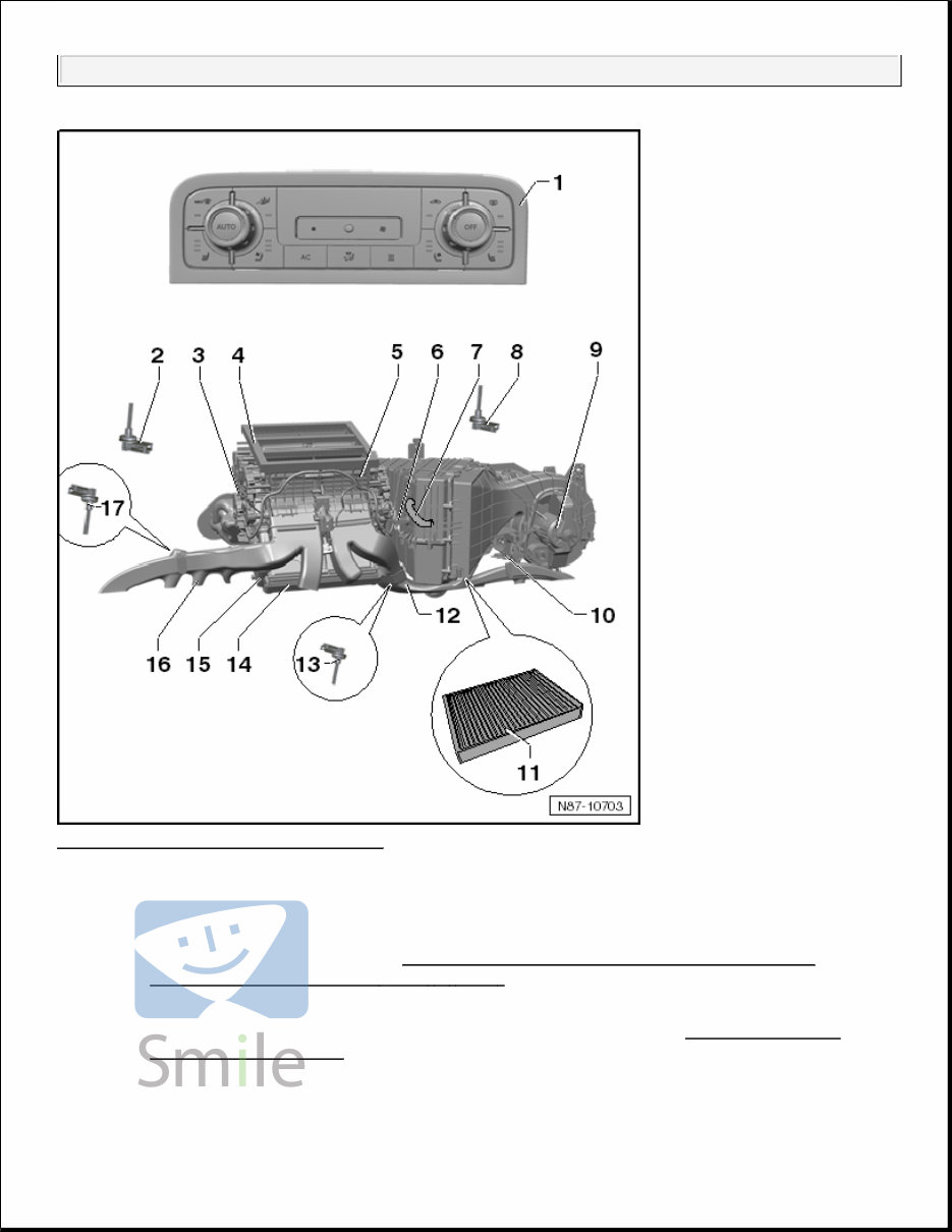
Fig. 1: Identifying Climatronic Overview Courtesy of VOLKSWAGEN GROUP OF AMERICA, INC. 1. Front A/C Display Control Head -E87- with Climatronic Control Module -J255- 2. Left Front Upper Body Outlet Temperature Sensor -G385- Removing and installing, refer to RIGHT AND LEFT FRONT UPPER BODY VENT TEMPERATURE SENSOR - G385 - / - G386 - . 3. Left Control Motors Arrangement of the control motors at the heating and A/C unit, refer to DOOR CONTROL MOTORS OVERVIEW . 4. Upper Part Of The Distribution Box 5. Right Control Motors HVAC Air Conditioning
Arrangement of the control motors at the heating and A/C unit, refer to DOOR CONTROL MOTORS OVERVIEW . 6. Evaporator Temperature Sensor -G308- Removing and installing, refer to EVAPORATOR TEMPERATURE SENSOR - G308 - . 7. Glove Compartment Cooling Hose 8. Right Front Upper Body Outlet Temperature Sensor -G386- Removing and installing, refer to RIGHT AND LEFT FRONT UPPER BODY VENT TEMPERATURE SENSOR - G385 - / - G386 - . 9. Fresh Air Blower -V2- Removing and installing, refer to FRESH AIR BLOWER - V2 - . 10. Fresh Air/Recirculating Air/Back Pressure Door Motor -V425- Removing and installing, refer to FRESH AIR/RECIRCULATING AIR/BACK PRESSURE DOOR MOTOR - V425 - . 11. Dust And Pollen Filter With Activated Charcoal Filter Element Removing and installing, refer to DUST AND POLLEN FILTER . 12. Front Passenger Side Footwell Vent Removing and installing, refer to FOOTWELL VENT, FRONT PASSENGER SIDE . 13. Right Footwell Vent Temperature Sensor -G262- Removing and installing, refer to RIGHT FOOTWELL VENT TEMPERATURE SENSOR - G262 - . 14. Heat Exchanger Removing and installing, refer to HEATER CORE . 15. Auxiliary Heater Heating Element -Z35- Removing and installing, refer to AUXILIARY HEATER HEATING ELEMENT - Z35 - . 16. Driver Side Footwell Vent Removing and installing, refer to FOOTWELL VENT, DRIVER SIDE . 17. Left Footwell Vent Temperature Sensor -G261- Removing and installing, refer to LEFT FOOTWELL VENT TEMPERATURE SENSOR - G261 - . CLIMATRONIC COMPONENTS OVERVIEW HVAC Air Conditioning
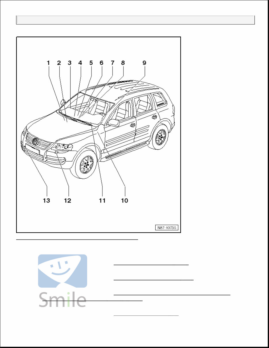
Fig. 2: Identifying Climatronic Components Overview Courtesy of VOLKSWAGEN GROUP OF AMERICA, INC. 1. Air Quality Sensor -G238- Removing and installing, refer to AIR QUALITY SENSOR - G238 - . 2. High Pressure Sensor -G65- Removing and installing, refer to HIGH PRESSURE SENSOR - G65 - . 3. Right Front Upper Body Outlet Temperature Sensor -G386- Removing and installing, refer to RIGHT AND LEFT FRONT UPPER BODY VENT TEMPERATURE SENSOR - G385 - / - G386 - . 4. Fresh Air Blower -V2- Removing and installing, refer to FRESH AIR BLOWER - V2 - . HVAC Air Conditioning
5. Evaporator Temperature Sensor -G308- Removing and installing, refer to EVAPORATOR TEMPERATURE SENSOR - G308 - . 6. Sunlight Photo Sensor -G107- Removing and installing, refer to SUNLIGHT PHOTO SENSOR - G107 - . 7. Right Footwell Vent Temperature Sensor -G262- Removing and installing, refer to RIGHT FOOTWELL VENT TEMPERATURE SENSOR - G262 - . 8. Climatronic Control Module -J255- Climatronic Control Module -J255-, Front A/C Display Control Head -E87- and Instrument Panel Interior Temperature Sensor (006785-3211) -G56- with Interior Temperature Sensor Fan -V42- are one component that cannot be disassembled. Removing and installing, refer to A/C DISPLAY CONTROL HEAD - E87 - WITH CLIMATRONIC CONTROL MODULE - J255 - . 9. Left Front Upper Body Outlet Temperature Sensor -G385- Removing and installing, refer to RIGHT AND LEFT FRONT UPPER BODY VENT TEMPERATURE SENSOR - G385 - / - G386 - . 10. Recirculation Pump -V55- Removing and installing, refer to RECIRCULATION PUMP - V55 - . 11. Left Footwell Vent Temperature Sensor -G261- Removing and installing, refer to LEFT FOOTWELL VENT TEMPERATURE SENSOR - G261 - . 12. A/C Compressor Regulator Valve -N280- A/C Compressor Regulator Valve -N280- and A/C compressor cannot be disassembled. A/C compressor, removing and installing, refer to TDI A/C COMPRESSOR , 3.6L A/C COMPRESSOR or Hybrid A/C COMPRESSOR . 13. Outside Air Temperature Sensor -G17- Removing and installing, refer to OUTSIDE AIR TEMPERATURE SENSOR - G17 - . CLIMATRONIC CONTROL MODULE J255 HARNESS CONNECTORS Special tools and workshop equipment required Test Box (Basic Unit) V.A.G 1598/14 Adapter V.A.G 1598/11 HVAC Air Conditioning
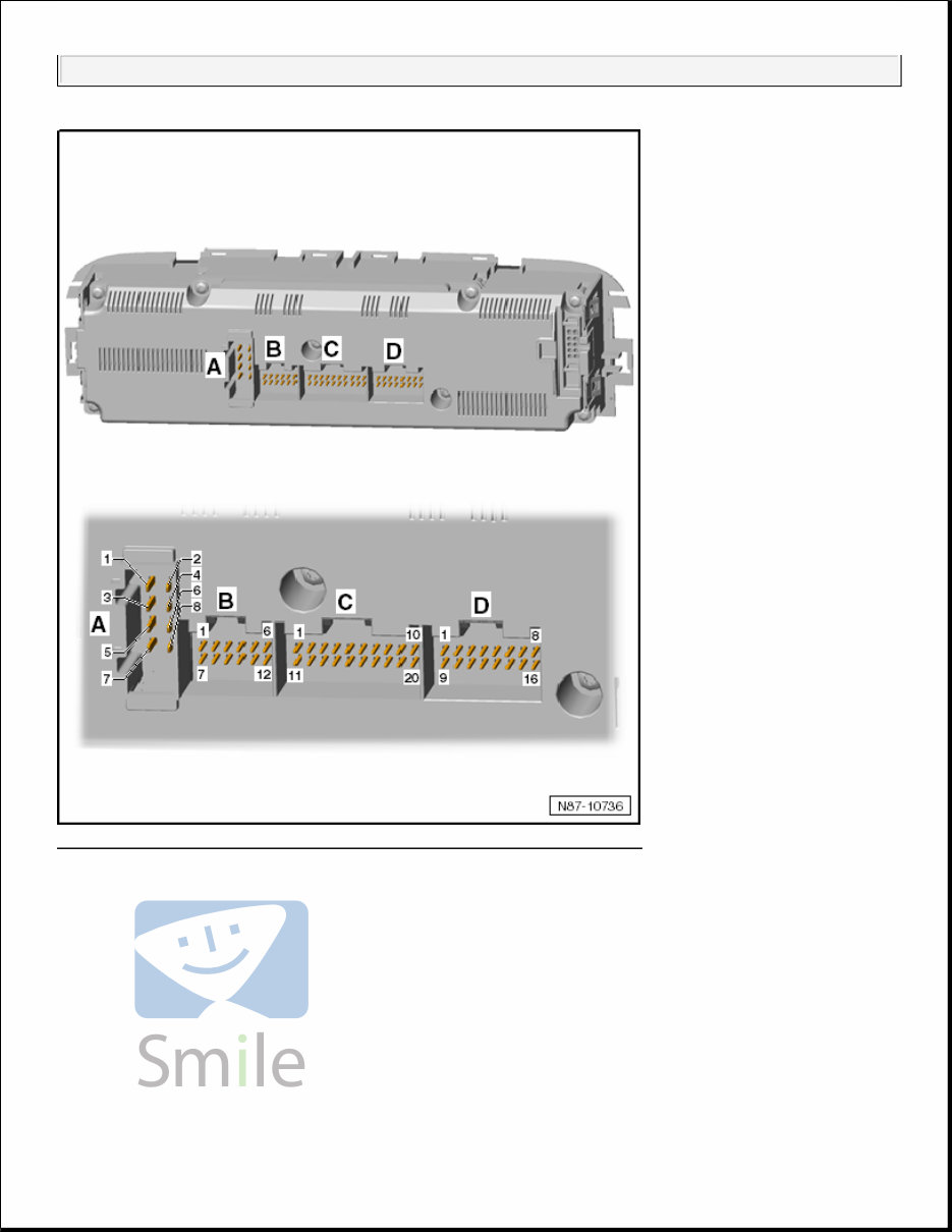
Fig. 3: Identifying Climatronic Control Module J255 Harness Connectors Courtesy of VOLKSWAGEN GROUP OF AMERICA, INC. 8-pin Harness Connector -A- T8n 1 - Terminal 30 2 - Terminal 31 3 - Not assigned 4 - Not assigned HVAC Air Conditioning
Get your hands on the 2013 Volkswagen Touareg Service & Repair Manual. Whether you're a professional mechanic or a DIY enthusiast, this manual provides comprehensive instructions and procedures to help you address your vehicle's repairs. Covering a wide range of sections including maintenance, engine, control system, mechanical repairs, fuel service specifications, emission control, and more, this manual includes detailed, step-by-step instructions, diagrams, illustrations, wiring schematics, and specifications to facilitate efficient vehicle repair. It is compatible with Windows and Mac systems and is fully printable, allowing you to print only the pages you need. With this manual, gain the confidence and technical know-how required to carry out repairs independently, ensuring the longevity and reliability of your vehicle. Additional language options are available where applicable.
Covers all models & all repairs A-Z
Vehicle-specific repair information
Complete step-by-step instructions, diagrams, illustrations, wiring schematics, and specifications
Printable and compatible with Windows and Mac
This Auto Repair Manual is an essential resource for both immediate car repairs and fun DIY projects. By using this manual, you not only save money but also expand your expertise in car maintenance and repair. It includes a comprehensive list of accessories and factory-detailed repair instructions, making it a valuable tool for both professional mechanics and DIY enthusiasts. Keep this reliable reference on your PC for quick access and enjoy the satisfaction of maintaining and repairing your vehicle with confidence.
Additional information about this service repair manual:
Compatible: All Versions of Windows and Mac
Printable: Yes
Language: English
Requirements: Adobe Reader and free online Win software