

2008 Volkswagen Polo 5 Doors Download Service & Repair Manual
What's Included?
Fast Download Speeds
Online & Offline Access
Access PDF Contents & Bookmarks
Full Search Facility
Print one or all pages of your manual
P
rote
cte
d
b
y
c
o
p
yrig
ht.
C
o
p
yin
g
fo
r
p
riv
a
t
e
o
r
c
o
m
m
e
r
c
i
a
l
p
u
r
p
o
s
e
s
,
i
n
p
a
r
t
o
r
i
n
wh
o
l
e
,
i
s
n
o
t
p
e
r
m
itte
d
u
n
le
s
s
a
uth
o
ris
e
d
b
y
V
olk
s
w
a
g
e
n
A
G
.
V
olks
w
a
g
e
n
A
G
d
o
e
s
n
ot
g
u
ara
nte
e
o
r
a
c
c
e
p
t
a
n
y
lia
b
ilit
y
w
it
h
r
e
s
p
e
c
t
t
o
t
h
e
c
o
r
r
e
c
t
n
e
s
s
o
f
i
n
f
o
r
m
a
ti
o
n
in
t
h
is
d
o
c
u
m
e
n
t.
C
o
p
yrig
ht
b
y
V
olk
s
w
a
g
e
n
A
G
.
Workshop Manual
Polo 2002 ➤
3-cylinder diesel engine
Engine ID
AMF BAY BNM BNV BMS BWB
Edition 12.2011
Service
Service Department. Technical Information

P
rote
cte
d
b
y
c
o
p
yrig
ht.
C
o
p
yin
g
fo
r
p
riv
a
t
e
o
r
c
o
m
m
e
r
c
i
a
l
p
u
r
p
o
s
e
s
,
i
n
p
a
r
t
o
r
i
n
wh
o
l
e
,
i
s
n
o
t
p
e
r
m
itte
d
u
n
le
s
s
a
uth
o
ris
e
d
b
y
V
olk
s
w
a
g
e
n
A
G
.
V
olks
w
a
g
e
n
A
G
d
o
e
s
n
ot
g
u
ara
nte
e
o
r
a
c
c
e
p
t
a
n
y
lia
b
ilit
y
w
it
h
r
e
s
p
e
c
t
t
o
t
h
e
c
o
r
r
e
c
t
n
e
s
s
o
f
i
n
f
o
r
m
a
ti
o
n
in
t
h
is
d
o
c
u
m
e
n
t.
C
o
p
yrig
ht
b
y
V
olk
s
w
a
g
e
n
A
G
.
List of Workshop Manual Repair Groups
Repair Group
00 - Technical data
10 - Removing and installing engine
13 - Crankshaft group
15 - Cylinder head, valve gear
17 - Lubrication
19 - Cooling
20 - Fuel supply system
21 - Turbocharging/supercharging
23 - Mixture preparation - injection
26 - Exhaust system
28 - Glow plug system
Technical information should always be available to the foremen and mechanics, because their
careful and constant adherence to the instructions is essential to ensure vehicle road-worthiness and
safety. In addition, the normal basic safety precautions for working on motor vehicles must, as a
matter of course, be observed.
Service
All rights reserved.
No reproduction without prior agreement from publisher.
Copyright © 2015 Volkswagen AG, Wolfsburg K0050240520

P
rote
cte
d
b
y
c
o
p
yrig
ht.
C
o
p
yin
g
fo
r
p
riv
a
t
e
o
r
c
o
m
m
e
r
c
i
a
l
p
u
r
p
o
s
e
s
,
i
n
p
a
r
t
o
r
i
n
wh
o
l
e
,
i
s
n
o
t
p
e
r
m
itte
d
u
n
le
s
s
a
uth
o
ris
e
d
b
y
V
olk
s
w
a
g
e
n
A
G
.
V
olks
w
a
g
e
n
A
G
d
o
e
s
n
ot
g
u
ara
nte
e
o
r
a
c
c
e
p
t
a
n
y
lia
b
ilit
y
w
it
h
r
e
s
p
e
c
t
t
o
t
h
e
c
o
r
r
e
c
t
n
e
s
s
o
f
i
n
f
o
r
m
a
ti
o
n
in
t
h
is
d
o
c
u
m
e
n
t.
C
o
p
yrig
ht
b
y
V
olk
s
w
a
g
e
n
A
G
.
Contents
00 - Technical data . . . . . . . . . . . . . . . . . . . . . . . . . . . . . . . . . . . . . . . . . . . . . . . . . . . . 1
1 Technical data . . . . . . . . . . . . . . . . . . . . . . . . . . . . . . . . . . . . . . . . . . . . . . . . . . . . . . . . . . 1
1.1 Engine number . . . . . . . . . . . . . . . . . . . . . . . . . . . . . . . . . . . . . . . . . . . . . . . . . . . . . . . . . . 1
1.2 Engine data . . . . . . . . . . . . . . . . . . . . . . . . . . . . . . . . . . . . . . . . . . . . . . . . . . . . . . . . . . . . 1
10 - Removing and installing engine . . . . . . . . . . . . . . . . . . . . . . . . . . . . . . . . . . . . . . 3
1 Removing and installing engine . . . . . . . . . . . . . . . . . . . . . . . . . . . . . . . . . . . . . . . . . . . . . . 3
1.1 Removing engine . . . . . . . . . . . . . . . . . . . . . . . . . . . . . . . . . . . . . . . . . . . . . . . . . . . . . . . . 3
1.2 Securing engine to assembly stand . . . . . . . . . . . . . . . . . . . . . . . . . . . . . . . . . . . . . . . . . . 9
1.3 Notes on installing . . . . . . . . . . . . . . . . . . . . . . . . . . . . . . . . . . . . . . . . . . . . . . . . . . . . . . . . 10
1.4 Assembly mountings . . . . . . . . . . . . . . . . . . . . . . . . . . . . . . . . . . . . . . . . . . . . . . . . . . . . . . 11
1.5 Additional information and assembly work for vehicles with air conditioner . . . . . . . . . . . . 12
13 - Crankshaft group . . . . . . . . . . . . . . . . . . . . . . . . . . . . . . . . . . . . . . . . . . . . . . . . . . 13
1 Dismantling and assembling engine . . . . . . . . . . . . . . . . . . . . . . . . . . . . . . . . . . . . . . . . . . 13
1.1 Assembly overview - toothed belt drive . . . . . . . . . . . . . . . . . . . . . . . . . . . . . . . . . . . . . . . . 13
1.2 Assembly overview - crankcase . . . . . . . . . . . . . . . . . . . . . . . . . . . . . . . . . . . . . . . . . . . . . . 15
1.3 Removing and installing poly V-belt . . . . . . . . . . . . . . . . . . . . . . . . . . . . . . . . . . . . . . . . . . 16
2 Sealing flange and flywheel . . . . . . . . . . . . . . . . . . . . . . . . . . . . . . . . . . . . . . . . . . . . . . . . 20
2.1 Assembly overview - sealing flange and flywheel, engine codes AMF, BAY, BNM, BNV . . 20
2.2 Assembly overview - sealing flange and flywheel, engine codes BMS, BWB . . . . . . . . . . 22
2.3 Renewing crankshaft oil seal - pulley end . . . . . . . . . . . . . . . . . . . . . . . . . . . . . . . . . . . . . . 23
2.4 Removing and installing sealing flange - pulley end . . . . . . . . . . . . . . . . . . . . . . . . . . . . . . 24
2.5 Renewing crankshaft sealing flange - flywheel end, engine codes BMS, BWB . . . . . . . . . . 27
2.6 Removing and installing engine speed sender G28 , engine codes BMS, BWB . . . . . . . . 34
3 Balancer shaft and retaining frame . . . . . . . . . . . . . . . . . . . . . . . . . . . . . . . . . . . . . . . . . . 36
3.1 Assembly overview - balancer shaft and retaining frame . . . . . . . . . . . . . . . . . . . . . . . . . . 36
3.2 Removing and installing balancer shaft . . . . . . . . . . . . . . . . . . . . . . . . . . . . . . . . . . . . . . . . 38
4 Crankshaft . . . . . . . . . . . . . . . . . . . . . . . . . . . . . . . . . . . . . . . . . . . . . . . . . . . . . . . . . . . . . . 43
4.1 Assembly overview - crankshaft . . . . . . . . . . . . . . . . . . . . . . . . . . . . . . . . . . . . . . . . . . . . . . 43
4.2 Crankshaft dimensions . . . . . . . . . . . . . . . . . . . . . . . . . . . . . . . . . . . . . . . . . . . . . . . . . . . . 44
5 Pistons and conrods . . . . . . . . . . . . . . . . . . . . . . . . . . . . . . . . . . . . . . . . . . . . . . . . . . . . . . 46
5.1 Assembly overview - pistons and conrods . . . . . . . . . . . . . . . . . . . . . . . . . . . . . . . . . . . . . . 46
5.2 Separating new conrods . . . . . . . . . . . . . . . . . . . . . . . . . . . . . . . . . . . . . . . . . . . . . . . . . . . . 48
5.3 Checking pistons, piston rings and cylinder bores . . . . . . . . . . . . . . . . . . . . . . . . . . . . . . . . 48
5.4 Checking piston projection at TDC . . . . . . . . . . . . . . . . . . . . . . . . . . . . . . . . . . . . . . . . . . . . 50
5.5 Piston and cylinder dimensions . . . . . . . . . . . . . . . . . . . . . . . . . . . . . . . . . . . . . . . . . . . . . . 51
15 - Cylinder head, valve gear . . . . . . . . . . . . . . . . . . . . . . . . . . . . . . . . . . . . . . . . . . 52
1 Cylinder head . . . . . . . . . . . . . . . . . . . . . . . . . . . . . . . . . . . . . . . . . . . . . . . . . . . . . . . . . . . . 52
1.1 Assembly overview - cylinder head . . . . . . . . . . . . . . . . . . . . . . . . . . . . . . . . . . . . . . . . . . 52
1.2 Removing, installing and tensioning toothed belt . . . . . . . . . . . . . . . . . . . . . . . . . . . . . . . . 56
1.3 Removing and installing cylinder head . . . . . . . . . . . . . . . . . . . . . . . . . . . . . . . . . . . . . . . . 66
1.4 Checking compression . . . . . . . . . . . . . . . . . . . . . . . . . . . . . . . . . . . . . . . . . . . . . . . . . . . . 70
2 Valve gear . . . . . . . . . . . . . . . . . . . . . . . . . . . . . . . . . . . . . . . . . . . . . . . . . . . . . . . . . . . . . . 73
2.1 Assembly overview - valve gear . . . . . . . . . . . . . . . . . . . . . . . . . . . . . . . . . . . . . . . . . . . . . . 73
2.2 Reworking valve seats . . . . . . . . . . . . . . . . . . . . . . . . . . . . . . . . . . . . . . . . . . . . . . . . . . . . 76
2.3 Checking valve guides . . . . . . . . . . . . . . . . . . . . . . . . . . . . . . . . . . . . . . . . . . . . . . . . . . . . 78
2.4 Renewing valve stem seals . . . . . . . . . . . . . . . . . . . . . . . . . . . . . . . . . . . . . . . . . . . . . . . . 78
2.5 Removing and installing camshaft . . . . . . . . . . . . . . . . . . . . . . . . . . . . . . . . . . . . . . . . . . . . 80
2.6 Removing and installing camshaft oil seal . . . . . . . . . . . . . . . . . . . . . . . . . . . . . . . . . . . . . . 84
Polo 2002 ➤
3-cylinder diesel engine - Edition 12.2011
Contents i

P
rote
cte
d
b
y
c
o
p
yrig
ht.
C
o
p
yin
g
fo
r
p
riv
a
t
e
o
r
c
o
m
m
e
r
c
i
a
l
p
u
r
p
o
s
e
s
,
i
n
p
a
r
t
o
r
i
n
wh
o
l
e
,
i
s
n
o
t
p
e
r
m
itte
d
u
n
le
s
s
a
uth
o
ris
e
d
b
y
V
olk
s
w
a
g
e
n
A
G
.
V
olks
w
a
g
e
n
A
G
d
o
e
s
n
ot
g
u
ara
nte
e
o
r
a
c
c
e
p
t
a
n
y
lia
b
ilit
y
w
it
h
r
e
s
p
e
c
t
t
o
t
h
e
c
o
r
r
e
c
t
n
e
s
s
o
f
i
n
f
o
r
m
a
ti
o
n
in
t
h
is
d
o
c
u
m
e
n
t.
C
o
p
yrig
ht
b
y
V
olk
s
w
a
g
e
n
A
G
.
17 - Lubrication . . . . . . . . . . . . . . . . . . . . . . . . . . . . . . . . . . . . . . . . . . . . . . . . . . . . . . 87
1 Engine oil . . . . . . . . . . . . . . . . . . . . . . . . . . . . . . . . . . . . . . . . . . . . . . . . . . . . . . . . . . . . . . 87
1.1 Oil capacities . . . . . . . . . . . . . . . . . . . . . . . . . . . . . . . . . . . . . . . . . . . . . . . . . . . . . . . . . . . . 87
1.2 Checking engine oil level . . . . . . . . . . . . . . . . . . . . . . . . . . . . . . . . . . . . . . . . . . . . . . . . . . 87
2 Parts of lubrication system . . . . . . . . . . . . . . . . . . . . . . . . . . . . . . . . . . . . . . . . . . . . . . . . . . 88
2.1 Assembly overview - parts of lubrication system . . . . . . . . . . . . . . . . . . . . . . . . . . . . . . . . 88
2.2 Assembly overview - oil filter bracket . . . . . . . . . . . . . . . . . . . . . . . . . . . . . . . . . . . . . . . . . . 91
2.3 Removing and installing oil sump . . . . . . . . . . . . . . . . . . . . . . . . . . . . . . . . . . . . . . . . . . . . 92
2.4 Checking oil pressure and oil pressure switch . . . . . . . . . . . . . . . . . . . . . . . . . . . . . . . . . . 93
19 - Cooling . . . . . . . . . . . . . . . . . . . . . . . . . . . . . . . . . . . . . . . . . . . . . . . . . . . . . . . . . . 96
1 Removing and installing parts of cooling system . . . . . . . . . . . . . . . . . . . . . . . . . . . . . . . . 96
1.1 Assembly overview - parts of cooling system, body side . . . . . . . . . . . . . . . . . . . . . . . . . . 96
1.2 Assembly overview - parts of cooling system, engine side . . . . . . . . . . . . . . . . . . . . . . . . 98
1.3 Coolant hose schematic diagram . . . . . . . . . . . . . . . . . . . . . . . . . . . . . . . . . . . . . . . . . . . . 99
1.4 Draining and filling coolant . . . . . . . . . . . . . . . . . . . . . . . . . . . . . . . . . . . . . . . . . . . . . . . . . . 101
1.5 Removing and installing radiator . . . . . . . . . . . . . . . . . . . . . . . . . . . . . . . . . . . . . . . . . . . . 105
1.6 Removing and installing coolant pump . . . . . . . . . . . . . . . . . . . . . . . . . . . . . . . . . . . . . . . . 106
1.7 Removing and installing thermostat . . . . . . . . . . . . . . . . . . . . . . . . . . . . . . . . . . . . . . . . . . 108
1.8 Checking cooling system for leaks . . . . . . . . . . . . . . . . . . . . . . . . . . . . . . . . . . . . . . . . . . . . 109
1.9 Checking engine oil cooler for leaks . . . . . . . . . . . . . . . . . . . . . . . . . . . . . . . . . . . . . . . . . . 111
20 - Fuel supply system . . . . . . . . . . . . . . . . . . . . . . . . . . . . . . . . . . . . . . . . . . . . . . . . 114
1 Removing and installing parts of fuel supply system . . . . . . . . . . . . . . . . . . . . . . . . . . . . . . 114
1.1 Safety precautions when working on fuel supply system . . . . . . . . . . . . . . . . . . . . . . . . . . 115
1.2 Rules for cleanliness . . . . . . . . . . . . . . . . . . . . . . . . . . . . . . . . . . . . . . . . . . . . . . . . . . . . . . 115
1.3 Assembly overview - fuel tank with attachments . . . . . . . . . . . . . . . . . . . . . . . . . . . . . . . . 116
1.4 Removing and installing fuel tank . . . . . . . . . . . . . . . . . . . . . . . . . . . . . . . . . . . . . . . . . . . . 118
1.5 Assembly overview - fuel filter . . . . . . . . . . . . . . . . . . . . . . . . . . . . . . . . . . . . . . . . . . . . . . 119
1.6 Removing and installing fuel cooler . . . . . . . . . . . . . . . . . . . . . . . . . . . . . . . . . . . . . . . . . . 122
1.7 Removing and installing fuel delivery unit . . . . . . . . . . . . . . . . . . . . . . . . . . . . . . . . . . . . . . 122
1.8 Removing and installing fuel gauge sender G . . . . . . . . . . . . . . . . . . . . . . . . . . . . . . . . . . 124
1.9 Checking fuel pump . . . . . . . . . . . . . . . . . . . . . . . . . . . . . . . . . . . . . . . . . . . . . . . . . . . . . . 124
1.10 Assembly overview - accelerator mechanism . . . . . . . . . . . . . . . . . . . . . . . . . . . . . . . . . . 125
1.11 Checking tandem pump . . . . . . . . . . . . . . . . . . . . . . . . . . . . . . . . . . . . . . . . . . . . . . . . . . . . 126
1.12 Removing and installing tandem pump . . . . . . . . . . . . . . . . . . . . . . . . . . . . . . . . . . . . . . . . 130
21 - Turbocharging/supercharging . . . . . . . . . . . . . . . . . . . . . . . . . . . . . . . . . . . . . . . . 133
1 Charge air system with turbocharger . . . . . . . . . . . . . . . . . . . . . . . . . . . . . . . . . . . . . . . . . . 133
1.1 Safety precautions . . . . . . . . . . . . . . . . . . . . . . . . . . . . . . . . . . . . . . . . . . . . . . . . . . . . . . . . 133
1.2 Rules for cleanliness . . . . . . . . . . . . . . . . . . . . . . . . . . . . . . . . . . . . . . . . . . . . . . . . . . . . . . 134
1.3 Installing hose connections with connector couplings . . . . . . . . . . . . . . . . . . . . . . . . . . . . 134
1.4 Hose connections with spring band ring . . . . . . . . . . . . . . . . . . . . . . . . . . . . . . . . . . . . . . . . 135
1.5 Assembly overview - turbocharger . . . . . . . . . . . . . . . . . . . . . . . . . . . . . . . . . . . . . . . . . . . . 135
1.6 Removing and installing turbocharger, engine codes BMS, BWB . . . . . . . . . . . . . . . . . . . . 140
1.7 Assembly overview - parts of charge air cooling . . . . . . . . . . . . . . . . . . . . . . . . . . . . . . . . 142
1.8 Checking charge air system for leaks . . . . . . . . . . . . . . . . . . . . . . . . . . . . . . . . . . . . . . . . 144
23 - Mixture preparation - injection . . . . . . . . . . . . . . . . . . . . . . . . . . . . . . . . . . . . . . . . 147
1 Repairing diesel direct injection system . . . . . . . . . . . . . . . . . . . . . . . . . . . . . . . . . . . . . . . . 147
1.1 Safety precautions . . . . . . . . . . . . . . . . . . . . . . . . . . . . . . . . . . . . . . . . . . . . . . . . . . . . . . . . 147
1.2 Rules for cleanliness . . . . . . . . . . . . . . . . . . . . . . . . . . . . . . . . . . . . . . . . . . . . . . . . . . . . . . 148
1.3 Assembly overview - intake manifold with intake manifold flap . . . . . . . . . . . . . . . . . . . . . . 148
1.4 Assembly overview - air filter . . . . . . . . . . . . . . . . . . . . . . . . . . . . . . . . . . . . . . . . . . . . . . . . 152
1.5 Assembly overview - unit injector . . . . . . . . . . . . . . . . . . . . . . . . . . . . . . . . . . . . . . . . . . . . 152
Polo 2002 ➤
3-cylinder diesel engine - Edition 12.2011
ii Contents
P
rote
cte
d
b
y
c
o
p
yrig
ht.
C
o
p
yin
g
fo
r
p
riv
a
t
e
o
r
c
o
m
m
e
r
c
i
a
l
p
u
r
p
o
s
e
s
,
i
n
p
a
r
t
o
r
i
n
wh
o
l
e
,
i
s
n
o
t
p
e
r
m
itte
d
u
n
le
s
s
a
uth
o
ris
e
d
b
y
V
olk
s
w
a
g
e
n
A
G
.
V
olks
w
a
g
e
n
A
G
d
o
e
s
n
ot
g
u
ara
nte
e
o
r
a
c
c
e
p
t
a
n
y
lia
b
ilit
y
w
it
h
r
e
s
p
e
c
t
t
o
t
h
e
c
o
r
r
e
c
t
n
e
s
s
o
f
i
n
f
o
r
m
a
ti
o
n
in
t
h
is
d
o
c
u
m
e
n
t.
C
o
p
yrig
ht
b
y
V
olk
s
w
a
g
e
n
A
G
.
1.6 Removing and installing unit injector . . . . . . . . . . . . . . . . . . . . . . . . . . . . . . . . . . . . . . . . . . 154
1.7 Adjusting non-contact gap of unit injectors . . . . . . . . . . . . . . . . . . . . . . . . . . . . . . . . . . . . . . 156
1.8 Removing and installing O-rings for unit injector . . . . . . . . . . . . . . . . . . . . . . . . . . . . . . . . 156
2 Engine control unit . . . . . . . . . . . . . . . . . . . . . . . . . . . . . . . . . . . . . . . . . . . . . . . . . . . . . . . . 159
2.1 Removing and installing engine control unit . . . . . . . . . . . . . . . . . . . . . . . . . . . . . . . . . . . . 159
2.2 Removing and installing anti-theft engine control unit , engine codes AMF, BAY, BNM,
BNV . . . . . . . . . . . . . . . . . . . . . . . . . . . . . . . . . . . . . . . . . . . . . . . . . . . . . . . . . . . . . . . . . . 159
2.3 Removing and installing anti-theft engine control unit , engine codes BMS, BWB . . . . . . 161
2.4 Reading and clearing engine control unit event memory . . . . . . . . . . . . . . . . . . . . . . . . . . 162
2.5 Adapting functions and components . . . . . . . . . . . . . . . . . . . . . . . . . . . . . . . . . . . . . . . . . . 163
26 - Exhaust system . . . . . . . . . . . . . . . . . . . . . . . . . . . . . . . . . . . . . . . . . . . . . . . . . . 165
1 Exhaust system . . . . . . . . . . . . . . . . . . . . . . . . . . . . . . . . . . . . . . . . . . . . . . . . . . . . . . . . . . 165
1.1 Assembly overview - front exhaust pipe with catalytic converter and silencer . . . . . . . . . . 165
1.2 Assembly overview - front exhaust pipe with particulate filter . . . . . . . . . . . . . . . . . . . . . . 167
1.3 Assembly overview - silencer, vehicles with particulate filter . . . . . . . . . . . . . . . . . . . . . . . . 168
1.4 Removing and installing front exhaust pipe with particulate filter . . . . . . . . . . . . . . . . . . . . 169
1.5 Aligning exhaust system free of stress . . . . . . . . . . . . . . . . . . . . . . . . . . . . . . . . . . . . . . . . 170
2 Exhaust gas recirculation system . . . . . . . . . . . . . . . . . . . . . . . . . . . . . . . . . . . . . . . . . . . . 173
2.1 Assembly overview - parts of exhaust gas recirculation system, engine code AMF . . . . . . 173
2.2 Assembly overview - parts of exhaust gas recirculation system, engine codes BAY, BNM,
BNV . . . . . . . . . . . . . . . . . . . . . . . . . . . . . . . . . . . . . . . . . . . . . . . . . . . . . . . . . . . . . . . . . . 174
2.3 Assembly overview - parts of exhaust gas recirculation system, engine codes BMS, BWB
. . . . . . . . . . . . . . . . . . . . . . . . . . . . . . . . . . . . . . . . . . . . . . . . . . . . . . . . . . . . . . . . . . . . . . . . 175
2.4 Assembly overview - exhaust gas recirculation cooler, engine codes BMS, BWB . . . . . . 176
2.5 Removing and installing exhaust gas recirculation cooler, engine codes BMS, BWB . . . . 177
2.6 Vacuum hose assembly . . . . . . . . . . . . . . . . . . . . . . . . . . . . . . . . . . . . . . . . . . . . . . . . . . . . 178
28 - Glow plug system . . . . . . . . . . . . . . . . . . . . . . . . . . . . . . . . . . . . . . . . . . . . . . . . . . 180
1 Checking glow plug system . . . . . . . . . . . . . . . . . . . . . . . . . . . . . . . . . . . . . . . . . . . . . . . . 180
1.1 Removing, installing and checking glow plugs . . . . . . . . . . . . . . . . . . . . . . . . . . . . . . . . . . 180
1.2 Characteristics of ceramic glow plugs . . . . . . . . . . . . . . . . . . . . . . . . . . . . . . . . . . . . . . . . 181
1.3 Removing, installing and checking ceramic glow pin plugs . . . . . . . . . . . . . . . . . . . . . . . . 181
Polo 2002 ➤
3-cylinder diesel engine - Edition 12.2011
Contents iii

P
rote
cte
d
b
y
c
o
p
yrig
ht.
C
o
p
yin
g
fo
r
p
riv
a
t
e
o
r
c
o
m
m
e
r
c
i
a
l
p
u
r
p
o
s
e
s
,
i
n
p
a
r
t
o
r
i
n
wh
o
l
e
,
i
s
n
o
t
p
e
r
m
itte
d
u
n
le
s
s
a
uth
o
ris
e
d
b
y
V
olk
s
w
a
g
e
n
A
G
.
V
olks
w
a
g
e
n
A
G
d
o
e
s
n
ot
g
u
ara
nte
e
o
r
a
c
c
e
p
t
a
n
y
lia
b
ilit
y
w
it
h
r
e
s
p
e
c
t
t
o
t
h
e
c
o
r
r
e
c
t
n
e
s
s
o
f
i
n
f
o
r
m
a
ti
o
n
in
t
h
is
d
o
c
u
m
e
n
t.
C
o
p
yrig
ht
b
y
V
olk
s
w
a
g
e
n
A
G
.
Polo 2002 ➤
3-cylinder diesel engine - Edition 12.2011
iv Contents
P
rote
cte
d
b
y
c
o
p
yrig
ht.
C
o
p
yin
g
fo
r
p
riv
a
t
e
o
r
c
o
m
m
e
r
c
i
a
l
p
u
r
p
o
s
e
s
,
i
n
p
a
r
t
o
r
i
n
wh
o
l
e
,
i
s
n
o
t
p
e
r
m
itte
d
u
n
le
s
s
a
uth
o
ris
e
d
b
y
V
olk
s
w
a
g
e
n
A
G
.
V
olks
w
a
g
e
n
A
G
d
o
e
s
n
ot
g
u
ara
nte
e
o
r
a
c
c
e
p
t
a
n
y
lia
b
ilit
y
w
it
h
r
e
s
p
e
c
t
t
o
t
h
e
c
o
r
r
e
c
t
n
e
s
s
o
f
i
n
f
o
r
m
a
ti
o
n
in
t
h
is
d
o
c
u
m
e
n
t.
C
o
p
yrig
ht
b
y
V
olk
s
w
a
g
e
n
A
G
.
00 – Technical data
1 Technical data
Engine number ⇒ page 1
Engine data ⇒ page 1
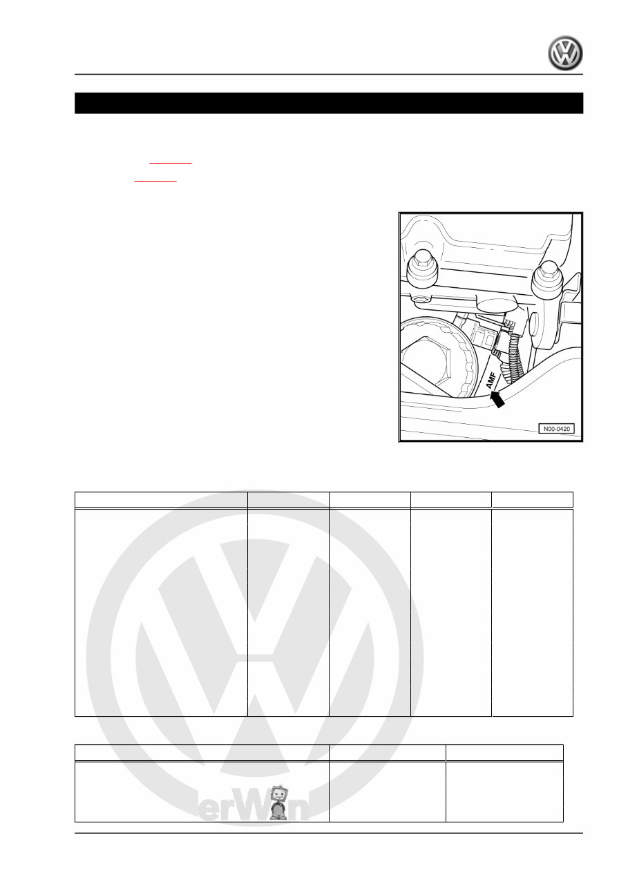
1.1 Engine number
The engine number („code letters“ and „serial number“) can be
found at the joint between engine and gearbox.
Additionally there is a sticker on the toothed belt guard with „en‐
gine code“ and „serial number“.
The engine code is also included on the vehicle data sticker.
1.2 Engine data
Edition 12.2011 Version 10
Engine code AMF BAY BNM BNV
Manufactured 11.01 ► 11.01 ► 03.05 ► 03.05 ►
Capacity l 1.4 1.4 1.4 1.4
Output kW at rpm 55/4000 55/4000 51/4000 58/4000
Torque Nm at rpm 195/2200 195/2200 155/2200 195/2200
Bore ∅ mm 79.5 79.5 79.5 79.5
Stroke mm 95.5 95.5 95.5 95.5
Compression ratio 19.5 19.5 19.5 19.5
Fuel according to DIN EN 590 DIN EN 590 DIN EN 590 DIN EN 590
Firing order 1-2-3 1-2-3 1-2-3 1-2-3
Catalytic converter yes yes yes yes
Diesel particulate filter no no no no
Exhaust gas recirculation yes yes yes yes
Turbocharging/supercharging yes yes yes yes
Charge air cooling yes yes yes yes
Engine code BMS BWB
Manufactured 01.06 ► 06.06 ►
Capacity l 1.4 1.4
Output kW at rpm 59/4000 51/4000
Torque Nm at rpm 195/2200 155/2200
Polo 2002 ➤
3-cylinder diesel engine - Edition 12.2011
1. Technical data 1
P
rote
cte
d
b
y
c
o
p
yrig
ht.
C
o
p
yin
g
fo
r
p
riv
a
t
e
o
r
c
o
m
m
e
r
c
i
a
l
p
u
r
p
o
s
e
s
,
i
n
p
a
r
t
o
r
i
n
wh
o
l
e
,
i
s
n
o
t
p
e
r
m
itte
d
u
n
le
s
s
a
uth
o
ris
e
d
b
y
V
olk
s
w
a
g
e
n
A
G
.
V
olks
w
a
g
e
n
A
G
d
o
e
s
n
ot
g
u
ara
nte
e
o
r
a
c
c
e
p
t
a
n
y
lia
b
ilit
y
w
it
h
r
e
s
p
e
c
t
t
o
t
h
e
c
o
r
r
e
c
t
n
e
s
s
o
f
i
n
f
o
r
m
a
ti
o
n
in
t
h
is
d
o
c
u
m
e
n
t.
C
o
p
yrig
ht
b
y
V
olk
s
w
a
g
e
n
A
G
.
Engine code BMS BWB
Bore ∅ mm 79.5 79.5
Stroke mm 95.5 95.5
Compression ratio 19.5 19.5
Fuel according to DIN EN 590 DIN EN 590
Firing order 1-2-3 1-2-3
Catalytic converter yes yes
Diesel particulate filter yes yes
Exhaust gas recirculation yes yes
Turbocharging/supercharging yes yes
Charge air cooling yes yes
Polo 2002 ➤
3-cylinder diesel engine - Edition 12.2011
2 Rep. gr.00 - Technical data
P
rote
cte
d
b
y
c
o
p
yrig
ht.
C
o
p
yin
g
fo
r
p
riv
a
t
e
o
r
c
o
m
m
e
r
c
i
a
l
p
u
r
p
o
s
e
s
,
i
n
p
a
r
t
o
r
i
n
wh
o
l
e
,
i
s
n
o
t
p
e
r
m
itte
d
u
n
le
s
s
a
uth
o
ris
e
d
b
y
V
olk
s
w
a
g
e
n
A
G
.
V
olks
w
a
g
e
n
A
G
d
o
e
s
n
ot
g
u
ara
nte
e
o
r
a
c
c
e
p
t
a
n
y
lia
b
ilit
y
w
it
h
r
e
s
p
e
c
t
t
o
t
h
e
c
o
r
r
e
c
t
n
e
s
s
o
f
i
n
f
o
r
m
a
ti
o
n
in
t
h
is
d
o
c
u
m
e
n
t.
C
o
p
yrig
ht
b
y
V
olk
s
w
a
g
e
n
A
G
.
10 – Removing and installing engine
1 Removing and installing engine
Removing engine ⇒ page 3 .
Securing engine to assembly stand ⇒ page 9 .
Notes on installing ⇒ page 10 .
Assembly mountings ⇒ page 11
Additional information and assembly work for vehicles with air
conditioner ⇒ page 12 .
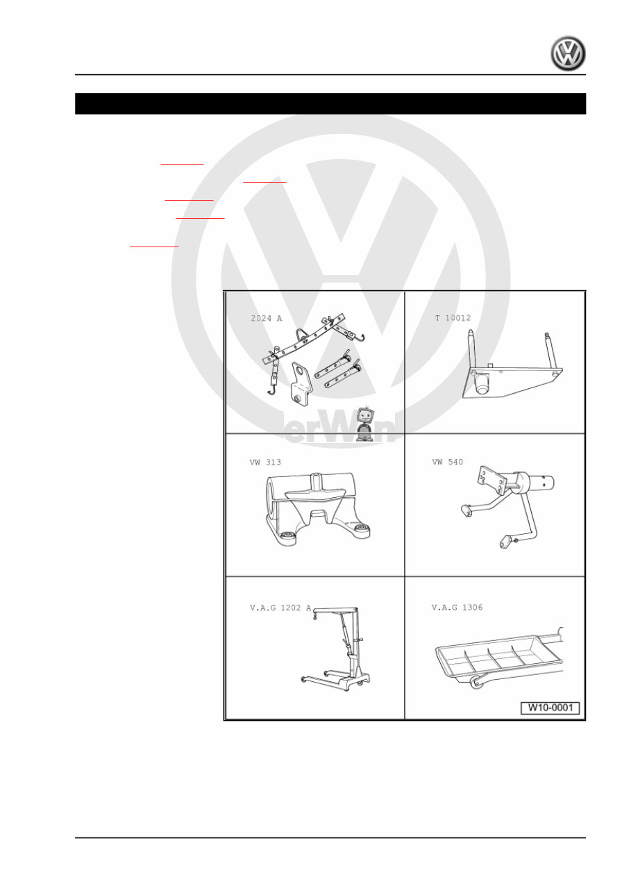
1.1 Removing engine
Special tools and workshop
equipment required
♦ Lifting tackle -VAS 2024A-
♦ Engine bracket -T10012-
♦ Support clamp -VW 313-
♦ Engine and gearbox sup‐
port -VW 540- or engine
and gearbox support -VAS
6095-
♦ Workshop hoist -V.A.G
1202 A- or workshop crane
-VAS 6100-
♦ Drip tray -V.A.G 1306- or
drip tray -VAS 6208-
Polo 2002 ➤
3-cylinder diesel engine - Edition 12.2011
1. Removing and installing engine 3
P
rote
cte
d
b
y
c
o
p
yrig
ht.
C
o
p
yin
g
fo
r
p
riv
a
t
e
o
r
c
o
m
m
e
r
c
i
a
l
p
u
r
p
o
s
e
s
,
i
n
p
a
r
t
o
r
i
n
wh
o
l
e
,
i
s
n
o
t
p
e
r
m
itte
d
u
n
le
s
s
a
uth
o
ris
e
d
b
y
V
olk
s
w
a
g
e
n
A
G
.
V
olks
w
a
g
e
n
A
G
d
o
e
s
n
ot
g
u
ara
nte
e
o
r
a
c
c
e
p
t
a
n
y
lia
b
ilit
y
w
it
h
r
e
s
p
e
c
t
t
o
t
h
e
c
o
r
r
e
c
t
n
e
s
s
o
f
i
n
f
o
r
m
a
ti
o
n
in
t
h
is
d
o
c
u
m
e
n
t.
C
o
p
yrig
ht
b
y
V
olk
s
w
a
g
e
n
A
G
.
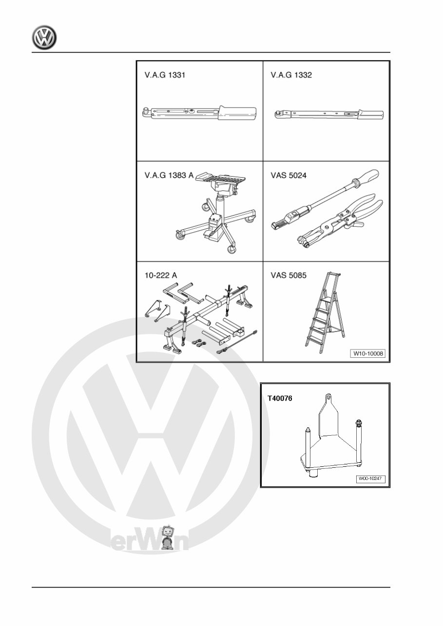
♦ Torque wrench -V.A.G
1331-
♦ Torque wrench -V.A.G
1332-
♦ Engine and gearbox jack -
V.A.G 1383/A-
♦ Spring-type clip pliers -VAS
5024-
♦ Stepladder -VAS 5085-
♦ Support bracket -10-222A-
♦ Engine support -T40076- (vehicles with no air conditioner)
Not illustrated:
♦ Container for removed parts -V.A.G 1698-
♦ Engine bung set -VAS 6122-
♦ Grease -G 000 100-
♦ Cable ties
Polo 2002 ➤
3-cylinder diesel engine - Edition 12.2011
4 Rep. gr.10 - Removing and installing engine
You're Reading a Preview
What's Included?
Fast Download Speeds
Online & Offline Access
Access PDF Contents & Bookmarks
Full Search Facility
Print one or all pages of your manual
$52.99
Viewed 75 Times Today


Secure transaction
What's Included?
Fast Download Speeds
Online & Offline Access
Access PDF Contents & Bookmarks
Full Search Facility
Print one or all pages of your manual
$52.99
Introducing the 2008 Volkswagen Polo 5 Doors Download Service & Repair Manual!
This comprehensive manual is a must-have for every owner of a 2008 Volkswagen Polo with 5 doors. Whether you are a seasoned mechanic or a DIY enthusiast, this manual will be your ultimate guide to service and repair your beloved Polo with ease.
- Step-by-step instructions: This manual provides detailed instructions for all maintenance and repair procedures, ensuring you can tackle any issue that may arise.
- Diagram illustrations: With the help of clear and precise diagrams, you'll easily understand the intricacies of your Polo's components and systems.
- Save time and money: By utilizing this download service & repair manual, you can avoid costly trips to the dealership or mechanic, performing repairs and services on your own terms.
- Comprehensive coverage: From engine maintenance and electrical system troubleshooting to brake repairs and suspension adjustments, this manual covers it all.
Models covered:
- Polo Trendline 1.2
- Polo Comfortline 1.4
- Polo Highline 1.6
Don't let maintenance and repairs hinder your enjoyment of your 2008 Volkswagen Polo. Get the 2008 Volkswagen Polo 5 Doors Download Service & Repair Manual today and take control of your car's well-being!


