1997-2006 Volkswagen Golf 4 Service & Repair Manual
What's Included?
Lifetime Access
Fast Download Speeds
Offline Viewing
Access Contents & Bookmarks
Full Search Facility
Print one or all pages of your manual
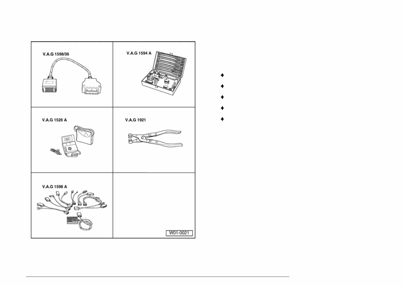
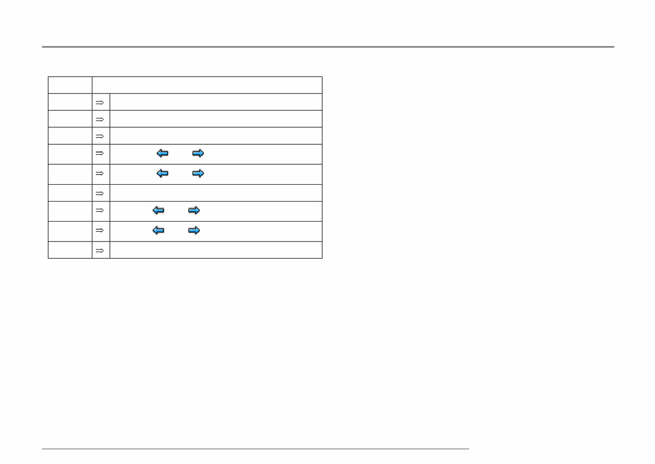
01-285 Electrical check of Mark 60 Special tools and equipment VAG 1598/36 Adapter VAG 1594 A Adapter set VAG 1526 A Hand multimeter VAG 1921 Pliers VAG 1598 A Test box Стр. 1 из 42 Electrical check of Mark 60 23.09.2004 http://127.0.0.1:8080/vw/servlet/Display?action=Goto&target=_top&type=repair&id=VW.A4.SU02.01.9&hit=35
01-286 The test steps from page Page 01 - 294 apply only to vehicles with ABS /EDL/ASR/ESP For vehicles on which the On Board Diagnostic (OBD) does not give any indication of the source of the malfunction. Work through the complete electrical check. For vehicles on which the OBD provides a direct indication of the source of the malfunction. Only carry out the test steps recommended in the DTC table (directed entry). An overview of all the test steps in the electrical check can be found on Page Page 01 - 294 . Стр. 2 из 42 Electrical check of Mark 60 23.09.2004 http://127.0.0.1:8080/vw/servlet/Display?action=Goto&target=_top&type=repair&id=VW.A4.SU02.01.9&hit=35
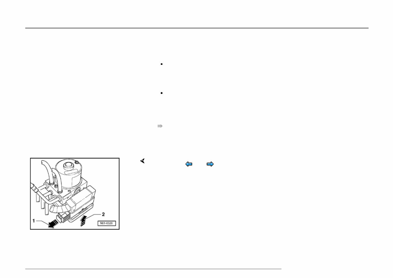
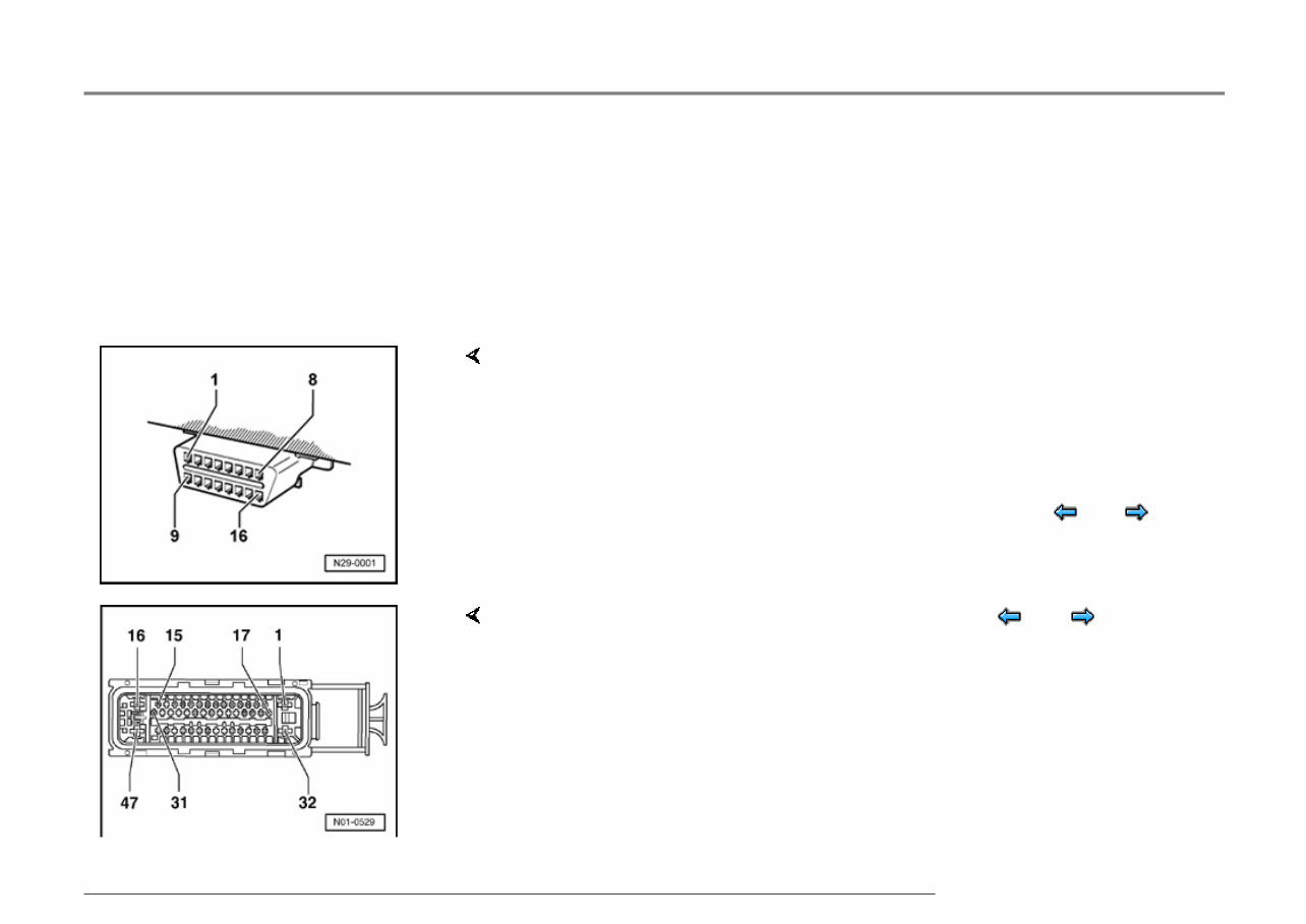
01-287 Test prerequisites Switch ignition and electrical consumers off before commencing the check (headlights, lighting, fans ...). Fuses must be OK (remove fuses from fuse holder to check). Electrical Wiring Diagrams, Troubleshooting & Component Locationsbinder - Pull fuse holder out of cable channel. - Release ABS Control Module (w/EDL) -J104- connector -arrow 1- and pull off -arrow 2-. Стр. 3 из 42 Electrical check of Mark 60 23.09.2004 http://127.0.0.1:8080/vw/servlet/Display?action=Goto&target=_top&type=repair&id=VW.A4.SU02.01.9&hit=35
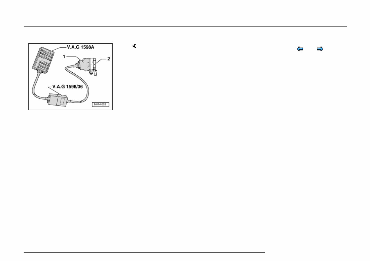
01-288 The specified values are matched to the V.A.G 1526 and are not necessarily applicable for other test modules. - Connect test box V.A.G 1598/36 -1- to multi-pin connector of ABS control module (w/EDL) -J104- -2-. Стр. 4 из 42 Electrical check of Mark 60 23.09.2004 http://127.0.0.1:8080/vw/servlet/Display?action=Goto&target=_top&type=repair&id=VW.A4.SU02.01.9&hit=35
01-289 Multi-pin connector with contact assignments Note: All contacts not listed are currently not assigned and must never be connected to other components! Contact assignment of connectors for voltage supply and self-diagnosis with the V.A.G 1551 scan tool Contact 4 = Ground (terminal 31) Contact 16 = Positive (terminal 30) Contact 7 = K wire to contact 2 of multi-pin connector T47 of ABS control module (w/EDL) -J104- Contact assignment of connector T47 wiring harness/ ABS control module (w/EDL) -J104- Стр. 5 из 42 Electrical check of Mark 60 23.09.2004 http://127.0.0.1:8080/vw/servlet/Display?action=Goto&target=_top&type=repair&id=VW.A4.SU02.01.9&hit=35
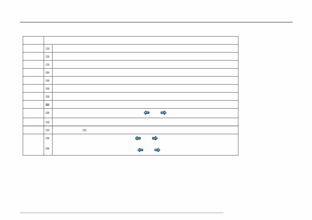
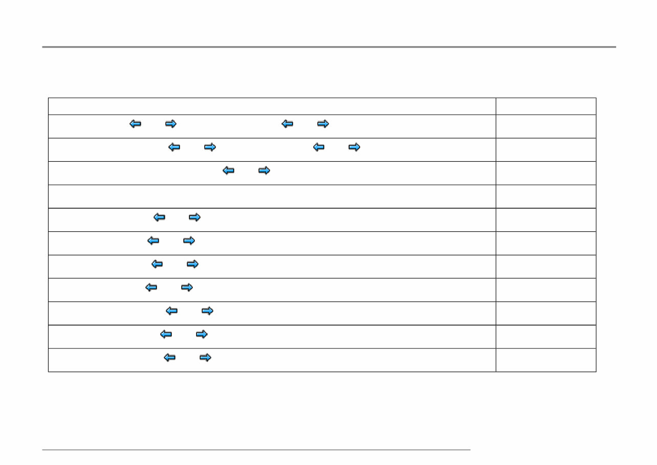
01-290 Contact Wiring connection to component ... 1 Voltage supply from battery + 2 Connector T16/7, K wire 3 Longitudinal acceleration sensor -G251- sensor wire(4MOTION vehicles only) 4 Voltage supply from ignition/starter switch 5 Longitudinal acceleration sensor -G251- Ground(4MOTION vehicles only) 6 Sensor for transverse acceleration -G200- 7 Longitudinal acceleration sensor -G251- voltage supply(4MOTION vehicles only) 8 Vehicles with navigation system only 9 Coding bridge to contact 12 (vehicles with ABS /EDL/ASR/ESP 4MOTION only) 10 Vehicles with navigation system only 11 Data bus wire Wiring diagrams 12 Coding bridge to contact 9 (vehicles with ABS /EDL/ASR/ESP 4MOTION only) Coding bridge to contact 38 (vehicles with ABS /EDL/ASR/ESP front wheel drive only) Стр. 6 из 42 Electrical check of Mark 60 23.09.2004 http://127.0.0.1:8080/vw/servlet/Display?action=Goto&target=_top&type=repair&id=VW.A4.SU02.01.9&hit=35
01-291 Contact Wiring connection to component ... 13 ASR/ESP button -E256- 14 Coding bridge to contact 38 (vehicles with ABS and ABS /EDL/ASR front wheel drive only) 15 Data bus wire Wiring diagrams 16 Ground point on left-hand longitudinal member 17 Vacant 18 Sender 1 for brake booster -G201- voltage supply 19 Sender 1 for brake booster -G201- signal wire 20 Sender 1 for brake booster -G201- ground wire 21 Vacant 22 Vacant 23 Vacant 24 Ground wire for sensor for transverse acceleration -G200- and sender for rotation rate -G202- 25 Vacant 26 Voltage supply for sensor for transverse acceleration -G200- and sender for rotation rate -G202- Стр. 7 из 42 Electrical check of Mark 60 23.09.2004 http://127.0.0.1:8080/vw/servlet/Display?action=Goto&target=_top&type=repair&id=VW.A4.SU02.01.9&hit=35
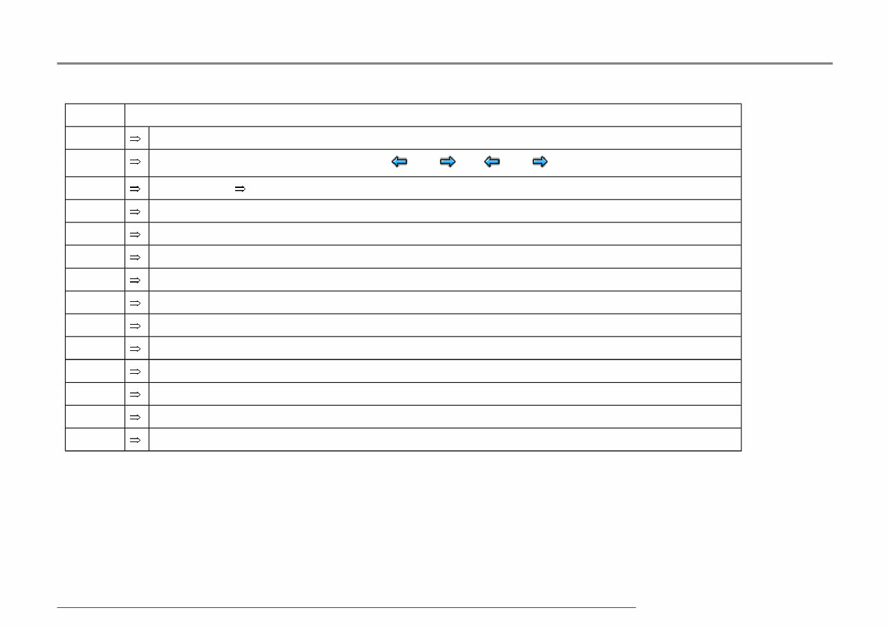
01-292 Contact Wiring connection to component ... 27 Vacant 28 Vacant 29 Vacant 30 Vacant 31 Vacant 32 Voltage supply from battery + 33 Right front ABS wheel speed sensor -G45- 34 Right front ABS wheel speed sensor -G45- 35 Vacant 36 Left rear ABS wheel speed sensor -G46- 37 Left rear ABS wheel speed sensor -G46- 38 Coding bridge to contact 12 (vehicles with ABS /EDL/ASR/ESP front wheel drive only) Coding bridge to contact 14 (vehicles with ABS and ABS /EDL/ASR front wheel drive only) Стр. 8 из 42 Electrical check of Mark 60 23.09.2004 http://127.0.0.1:8080/vw/servlet/Display?action=Goto&target=_top&type=repair&id=VW.A4.SU02.01.9&hit=35
01-293 Contact Wiring connection to component ... 39 Vacant 40 Sender for rotation rate -G202- signal wire 41 Brake light switch -F- 42 Right rear ABS wheel speed sensor -G44- 43 Right rear ABS wheel speed sensor -G44- 44 Vacant 45 Left front ABS wheel speed sensor -G47- 46 Left front ABS wheel speed sensor -G47- 47 Ground point on left-hand longitudinal member Стр. 9 из 42 Electrical check of Mark 60 23.09.2004 http://127.0.0.1:8080/vw/servlet/Display?action=Goto&target=_top&type=repair&id=VW.A4.SU02.01.9&hit=35
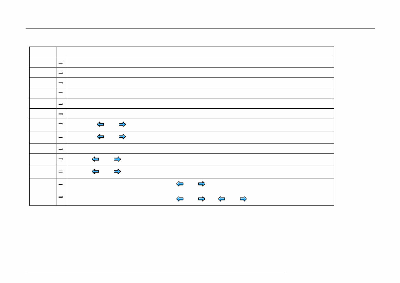
01-294 Test step overview Component to be tested Voltage supply for ABS hydraulic pump -V64- to ABS control module (w/EDL) -J104- - Perform test step 1 Voltage supply for valves in ABS hydraulic unit -N55- to ABS control module (w/EDL) -J104- - Perform test step 2 Voltage supply (ignition/starter switch) to ABS control module (w/EDL) -J104- - Perform test step 3 Function of brake light switch -F- - Perform test step 4 Resistance of right front ABS wheel speed sensor -G45- - Perform test step 5 Resistance of left front ABS wheel speed sensor -G47- - Perform test step 6 Resistance of right rear ABS wheel speed sensor -G44- - Perform test step 7 Resistance of left rear ABS wheel speed sensor -G46- - Perform test step 8 Voltage signal of right front ABS wheel speed sensor -G45- - Perform test step 9 Voltage signal of left front ABS wheel speed sensor -G47- - Perform test step 10 Voltage signal of right rear ABS wheel speed sensor -G44- - Perform test step 11 Стр. 10 из 42 Electrical check of Mark 60 23.09.2004 http://127.0.0.1:8080/vw/servlet/Display?action=Goto&target=_top&type=repair&id=VW.A4.SU02.01.9&hit=35
The VW VOLKSWAGEN GOLF 4 1997-2006 Service Repair Manual is a comprehensive guide designed to assist Volkswagen Golf 4 owners in maintaining and repairing their vehicles. This manual covers the years 1997 to 2006, providing detailed instructions and diagrams to help users perform various service and repair tasks on their Volkswagen Golf 4 models.
Key features of the VW VOLKSWAGEN GOLF 4 1997-2006 Service Repair Manual include:
Step-by-step instructions: The manual provides easy-to-follow, detailed instructions for performing various service and repair tasks on the Volkswagen Golf 4 models.
Comprehensive coverage: With coverage from 1997 to 2006, the manual includes information on servicing and repairing different components of the vehicle, including the engine, transmission, electrical system, suspension, brakes, and more.
Detailed diagrams: The manual is accompanied by diagrams and illustrations that aid in the understanding of various repair procedures, making it easier for users to diagnose and fix issues.
Troubleshooting tips: In addition to the repair procedures, the manual provides troubleshooting tips for common problems faced by Volkswagen Golf 4 owners, helping them identify and resolve issues efficiently.
Technical specifications: The manual also includes technical specifications and recommended maintenance schedules, ensuring that users have all the necessary information to keep their Volkswagen Golf 4 in optimal condition.
Whether you are a Volkswagen Golf 4 owner looking to perform routine maintenance or tackle more complex repairs, the VW VOLKSWAGEN GOLF 4 1997-2006 Service Repair Manual is an indispensable resource that will guide you through the process step-by-step, ensuring that your vehicle receives the care it needs to continue running smoothly.
Recently Viewed
5,521,897Happy Clients
2,594,462eManuals
1,120,453Trusted Sellers
15Years in Business
Price:
Actual Price:
1997-2006 Volkswagen Golf 4 Service & Repair Manual