P
r o t e
c t e
d
b
y
c
o
p
y r i g
h t .
C
o
p
y i n
g
f o
r
p
r i v
a
t
e
o
r
c
o
m
m
e
r
c
i
a
l
p
u
r
p
o
s
e
s
,
i
n
p
a
r
t
o
r
i
n
wh
o
l
e
,
i
s
n
o
t
p
e
r
m
i t t e
d
u
n
l e
s
s
a
u t h
o
r i s
e
d
b
y
V
o l k
s
w
a
g
e
n
A
G
.
V
o l k s
w
a
g
e
n
A
G
d
o
e
s
n
o t
g
u
a r a
n t e
e
o
r
a
c
c
e
p
t
a
n
y
l i a
b
i l i t
y
w
i t
h
r
e
s
p
e
c
t
t
o
t
h
e
c
o
r
r
e
c
t
n
e
s
s
o
f
i
n
f
o
r
m
a
t i
o
n
i n
t
h
i s
d
o
c
u
m
e
n
t .
C
o
p
y r i g
h t
b
y
V
o l k
s
w
a
g
e
n
A
G
.
Workshop Manual
Golf 2013 ➤
Golf 2015 ➤
Golf Variant 2014 ➤
Golf Variant 2015 ➤
4-cyl. direct injection engine (2.0 l, 4 V, turbocharger,
chain drive, generation III) Volkswagen R GmbH
Engine ID
CJXC CJXB
CYF
B
Edition 07.2015
Service
Service Department. Technical Information
P
r o t e
c t e
d
b
y
c
o
p
y r i g
h t .
C
o
p
y i n
g
f o
r
p
r i v
a
t
e
o
r
c
o
m
m
e
r
c
i
a
l
p
u
r
p
o
s
e
s
,
i
n
p
a
r
t
o
r
i
n
wh
o
l
e
,
i
s
n
o
t
p
e
r
m
i t t e
d
u
n
l e
s
s
a
u t h
o
r i s
e
d
b
y
V
o l k
s
w
a
g
e
n
A
G
.
V
o l k s
w
a
g
e
n
A
G
d
o
e
s
n
o t
g
u
a r a
n t e
e
o
r
a
c
c
e
p
t
a
n
y
l i a
b
i l i t
y
w
i t
h
r
e
s
p
e
c
t
t
o
t
h
e
c
o
r
r
e
c
t
n
e
s
s
o
f
i
n
f
o
r
m
a
t i
o
n
i n
t
h
i s
d
o
c
u
m
e
n
t .
C
o
p
y r i g
h t
b
y
V
o l k
s
w
a
g
e
n
A
G
.
List of Workshop Manual Repair Groups
Repair Group
00 - Technical data
10 - Removing and installing engine
13 - Crankshaft group
15 - Cylinder head, valve gear
17 - Lubrication
19 - Cooling
21 - Turbocharging/supercharging
24 - Mixture preparation - injection
26 - Exhaust system
28 - Ignition system
Technical information should always be available to the foremen and mechanics, because their
careful and constant adherence to the instructions is essential to ensure vehicle road-worthiness and
safety. In addition, the normal basic safety precautions for working on motor vehicles must, as a
matter of course, be observed.
Service
All rights reserved.
No reproduction without prior agreement from publisher.
Copyright © 2015 Volkswagen AG, Wolfsburg D4B803919C7
P
r o t e
c t e
d
b
y
c
o
p
y r i g
h t .
C
o
p
y i n
g
f o
r
p
r i v
a
t
e
o
r
c
o
m
m
e
r
c
i
a
l
p
u
r
p
o
s
e
s
,
i
n
p
a
r
t
o
r
i
n
wh
o
l
e
,
i
s
n
o
t
p
e
r
m
i t t e
d
u
n
l e
s
s
a
u t h
o
r i s
e
d
b
y
V
o l k
s
w
a
g
e
n
A
G
.
V
o l k s
w
a
g
e
n
A
G
d
o
e
s
n
o t
g
u
a r a
n t e
e
o
r
a
c
c
e
p
t
a
n
y
l i a
b
i l i t
y
w
i t
h
r
e
s
p
e
c
t
t
o
t
h
e
c
o
r
r
e
c
t
n
e
s
s
o
f
i
n
f
o
r
m
a
t i
o
n
i n
t
h
i s
d
o
c
u
m
e
n
t .
C
o
p
y r i g
h t
b
y
V
o l k
s
w
a
g
e
n
A
G
.
Contents
00 - Technical data . . . . . . . . . . . . . . . . . . . . . . . . . . . . . . . . . . . . . . . . . . . . . . . . . . . . 1
1 Identification . . . . . . . . . . . . . . . . . . . . . . . . . . . . . . . . . . . . . . . . . . . . . . . . . . . . . . . . . . . . 1
1.1 Engine number, engine data . . . . . . . . . . . . . . . . . . . . . . . . . . . . . . . . . . . . . . . . . . . . . . . . 1
2 Safety instructions . . . . . . . . . . . . . . . . . . . . . . . . . . . . . . . . . . . . . . . . . . . . . . . . . . . . . . . . 3
2.1 Safety precautions when working on fuel supply system . . . . . . . . . . . . . . . . . . . . . . . . . . 3
2.2 Safety precautions when working on vehicles with a Start/Stop system . . . . . . . . . . . . . . 3
2.3 Safety precautions during road tests in which testing and measuring equipment is used . . 4
2.4 Safety precautions when working on ignition system . . . . . . . . . . . . . . . . . . . . . . . . . . . . . . 4
2.5 Safety precautions when working on cooling system . . . . . . . . . . . . . . . . . . . . . . . . . . . . . . 5
3 Repair instructions . . . . . . . . . . . . . . . . . . . . . . . . . . . . . . . . . . . . . . . . . . . . . . . . . . . . . . . . 6
3.1 Rules for cleanliness . . . . . . . . . . . . . . . . . . . . . . . . . . . . . . . . . . . . . . . . . . . . . . . . . . . . . . 6
3.2 Foreign objects in engine . . . . . . . . . . . . . . . . . . . . . . . . . . . . . . . . . . . . . . . . . . . . . . . . . . 6
3.3 Contact corrosion . . . . . . . . . . . . . . . . . . . . . . . . . . . . . . . . . . . . . . . . . . . . . . . . . . . . . . . . 6
3.4 Routing and securing lines . . . . . . . . . . . . . . . . . . . . . . . . . . . . . . . . . . . . . . . . . . . . . . . . . . 7
3.5 Installing coolers, condensers and radiators . . . . . . . . . . . . . . . . . . . . . . . . . . . . . . . . . . . . 7
3.6 Testing vacuum system . . . . . . . . . . . . . . . . . . . . . . . . . . . . . . . . . . . . . . . . . . . . . . . . . . . . 7
10 - Removing and installing engine . . . . . . . . . . . . . . . . . . . . . . . . . . . . . . . . . . . . . . 9
1 Removing and installing engine . . . . . . . . . . . . . . . . . . . . . . . . . . . . . . . . . . . . . . . . . . . . . . 9
1.1 Removing engine . . . . . . . . . . . . . . . . . . . . . . . . . . . . . . . . . . . . . . . . . . . . . . . . . . . . . . . . 9
1.2 Separating engine and gearbox . . . . . . . . . . . . . . . . . . . . . . . . . . . . . . . . . . . . . . . . . . . . . . 17
1.3 Securing engine on engine and gearbox support . . . . . . . . . . . . . . . . . . . . . . . . . . . . . . . . 22
1.4 Installing engine . . . . . . . . . . . . . . . . . . . . . . . . . . . . . . . . . . . . . . . . . . . . . . . . . . . . . . . . . . 24
2 Assembly mountings . . . . . . . . . . . . . . . . . . . . . . . . . . . . . . . . . . . . . . . . . . . . . . . . . . . . . . 28
2.1 Assembly overview - assembly mountings . . . . . . . . . . . . . . . . . . . . . . . . . . . . . . . . . . . . . . 28
2.2 Supporting engine in installation position . . . . . . . . . . . . . . . . . . . . . . . . . . . . . . . . . . . . . . 30
2.3 Removing and installing engine mounting . . . . . . . . . . . . . . . . . . . . . . . . . . . . . . . . . . . . . . 33
2.4 Removing and installing gearbox mounting . . . . . . . . . . . . . . . . . . . . . . . . . . . . . . . . . . . . 33
2.5 Removing and installing pendulum support . . . . . . . . . . . . . . . . . . . . . . . . . . . . . . . . . . . . 35
2.6 Checking adjustment of assembly mountings . . . . . . . . . . . . . . . . . . . . . . . . . . . . . . . . . . 35
2.7 Adjusting assembly mountings . . . . . . . . . . . . . . . . . . . . . . . . . . . . . . . . . . . . . . . . . . . . . . 35
3 Engine cover panel . . . . . . . . . . . . . . . . . . . . . . . . . . . . . . . . . . . . . . . . . . . . . . . . . . . . . . . . 37
3.1 Removing and installing engine cover panel . . . . . . . . . . . . . . . . . . . . . . . . . . . . . . . . . . . . 37
13 - Crankshaft group . . . . . . . . . . . . . . . . . . . . . . . . . . . . . . . . . . . . . . . . . . . . . . . . . . 38
1 Cylinder block (pulley end) . . . . . . . . . . . . . . . . . . . . . . . . . . . . . . . . . . . . . . . . . . . . . . . . . . 38
1.1 Assembly overview - cylinder block (pulley end) . . . . . . . . . . . . . . . . . . . . . . . . . . . . . . . . 38
1.2 Removing and installing poly V-belt . . . . . . . . . . . . . . . . . . . . . . . . . . . . . . . . . . . . . . . . . . 40
1.3 Removing and installing tensioning device for poly V-belt . . . . . . . . . . . . . . . . . . . . . . . . . . 41
1.4 Removing and installing ancillary bracket . . . . . . . . . . . . . . . . . . . . . . . . . . . . . . . . . . . . . . 41
1.5 Removing and installing vibration damper . . . . . . . . . . . . . . . . . . . . . . . . . . . . . . . . . . . . . . 43
1.6 Removing and installing engine support . . . . . . . . . . . . . . . . . . . . . . . . . . . . . . . . . . . . . . 48
1.7 Renewing crankshaft oil seal - belt pulley end . . . . . . . . . . . . . . . . . . . . . . . . . . . . . . . . . . 49
2 Cylinder block, gearbox end . . . . . . . . . . . . . . . . . . . . . . . . . . . . . . . . . . . . . . . . . . . . . . . . 52
2.1 Assembly overview - cylinder block, gearbox end . . . . . . . . . . . . . . . . . . . . . . . . . . . . . . . . 52
2.2 Removing and installing flywheel . . . . . . . . . . . . . . . . . . . . . . . . . . . . . . . . . . . . . . . . . . . . 53
2.3 Removing and installing sealing flange on gearbox side . . . . . . . . . . . . . . . . . . . . . . . . . . 54
3 Crankshaft . . . . . . . . . . . . . . . . . . . . . . . . . . . . . . . . . . . . . . . . . . . . . . . . . . . . . . . . . . . . . . 57
3.1 Assembly overview - crankshaft . . . . . . . . . . . . . . . . . . . . . . . . . . . . . . . . . . . . . . . . . . . . . . 57
3.2 Removing and installing sender wheel . . . . . . . . . . . . . . . . . . . . . . . . . . . . . . . . . . . . . . . . 58
3.3 Renewing needle bearing in crankshaft . . . . . . . . . . . . . . . . . . . . . . . . . . . . . . . . . . . . . . . . 59
3.4 Allocation of main bearing shells . . . . . . . . . . . . . . . . . . . . . . . . . . . . . . . . . . . . . . . . . . . . 61
Golf 2013 ➤ , Golf 2015 ➤ , Golf Variant 2014 ➤ , Golf Variant 2015 ➤
4-cyl. direct injection engine (2.0 l, 4 V, turbocharger, chain drive, generation III) Volkswagen R GmbH
- Edition 07.2015
Contents i
P
r o t e
c t e
d
b
y
c
o
p
y r i g
h t .
C
o
p
y i n
g
f o
r
p
r i v
a
t
e
o
r
c
o
m
m
e
r
c
i
a
l
p
u
r
p
o
s
e
s
,
i
n
p
a
r
t
o
r
i
n
wh
o
l
e
,
i
s
n
o
t
p
e
r
m
i t t e
d
u
n
l e
s
s
a
u t h
o
r i s
e
d
b
y
V
o l k
s
w
a
g
e
n
A
G
.
V
o l k s
w
a
g
e
n
A
G
d
o
e
s
n
o t
g
u
a r a
n t e
e
o
r
a
c
c
e
p
t
a
n
y
l i a
b
i l i t
y
w
i t
h
r
e
s
p
e
c
t
t
o
t
h
e
c
o
r
r
e
c
t
n
e
s
s
o
f
i
n
f
o
r
m
a
t i
o
n
i n
t
h
i s
d
o
c
u
m
e
n
t .
C
o
p
y r i g
h t
b
y
V
o l k
s
w
a
g
e
n
A
G
.
3.5 Crankshaft dimensions . . . . . . . . . . . . . . . . . . . . . . . . . . . . . . . . . . . . . . . . . . . . . . . . . . . . 62
3.6 Measuring axial clearance of crankshaft . . . . . . . . . . . . . . . . . . . . . . . . . . . . . . . . . . . . . . 62
3.7 Measuring radial clearance of crankshaft . . . . . . . . . . . . . . . . . . . . . . . . . . . . . . . . . . . . . . 63
4 Balancer shaft . . . . . . . . . . . . . . . . . . . . . . . . . . . . . . . . . . . . . . . . . . . . . . . . . . . . . . . . . . 64
4.1 Assembly overview - balancer shaft . . . . . . . . . . . . . . . . . . . . . . . . . . . . . . . . . . . . . . . . . . 64
4.2 Removing and installing balancer shaft . . . . . . . . . . . . . . . . . . . . . . . . . . . . . . . . . . . . . . . . 65
4.3 Renewing oil seal for balance shaft (inlet side) . . . . . . . . . . . . . . . . . . . . . . . . . . . . . . . . . . 69
5 Pistons and conrods . . . . . . . . . . . . . . . . . . . . . . . . . . . . . . . . . . . . . . . . . . . . . . . . . . . . . . 71
5.1 Assembly overview - pistons and conrods . . . . . . . . . . . . . . . . . . . . . . . . . . . . . . . . . . . . . . 71
5.2 Removing and installing pistons . . . . . . . . . . . . . . . . . . . . . . . . . . . . . . . . . . . . . . . . . . . . . . 72
5.3 Separating new conrod . . . . . . . . . . . . . . . . . . . . . . . . . . . . . . . . . . . . . . . . . . . . . . . . . . . . 74
5.4 Checking piston and cylinder bore . . . . . . . . . . . . . . . . . . . . . . . . . . . . . . . . . . . . . . . . . . . . 74
5.5 Checking radial clearance of conrods . . . . . . . . . . . . . . . . . . . . . . . . . . . . . . . . . . . . . . . . 76
15 - Cylinder head, valve gear . . . . . . . . . . . . . . . . . . . . . . . . . . . . . . . . . . . . . . . . . . 77
1 Cover for timing chain . . . . . . . . . . . . . . . . . . . . . . . . . . . . . . . . . . . . . . . . . . . . . . . . . . . . 77
1.1 Assembly overview - cover for timing chain . . . . . . . . . . . . . . . . . . . . . . . . . . . . . . . . . . . . 77
1.2 Removing and installing upper timing chain cover . . . . . . . . . . . . . . . . . . . . . . . . . . . . . . . . 79
1.3 Removing and installing timing chain cover (bottom) . . . . . . . . . . . . . . . . . . . . . . . . . . . . . . 81
2 Chain drive . . . . . . . . . . . . . . . . . . . . . . . . . . . . . . . . . . . . . . . . . . . . . . . . . . . . . . . . . . . . . . 85
2.1 Assembly overview - camshaft timing chains . . . . . . . . . . . . . . . . . . . . . . . . . . . . . . . . . . . . 85
2.2 Assembly overview - drive chain for balancer shaft . . . . . . . . . . . . . . . . . . . . . . . . . . . . . . 86
2.3 Removing and installing camshaft timing chain . . . . . . . . . . . . . . . . . . . . . . . . . . . . . . . . . . 88
2.4 Removing and installing drive chain for balancer shaft . . . . . . . . . . . . . . . . . . . . . . . . . . . . 101
2.5 Checking chain elongation . . . . . . . . . . . . . . . . . . . . . . . . . . . . . . . . . . . . . . . . . . . . . . . . . . 103
2.6 Checking valve timing . . . . . . . . . . . . . . . . . . . . . . . . . . . . . . . . . . . . . . . . . . . . . . . . . . . . 103
3 Cylinder head . . . . . . . . . . . . . . . . . . . . . . . . . . . . . . . . . . . . . . . . . . . . . . . . . . . . . . . . . . . . 107
3.1 Assembly overview - cylinder head . . . . . . . . . . . . . . . . . . . . . . . . . . . . . . . . . . . . . . . . . . 107
3.2 Removing and installing cylinder head . . . . . . . . . . . . . . . . . . . . . . . . . . . . . . . . . . . . . . . . 109
3.3 Removing and installing vacuum pump . . . . . . . . . . . . . . . . . . . . . . . . . . . . . . . . . . . . . . . . 117
3.4 Checking compression . . . . . . . . . . . . . . . . . . . . . . . . . . . . . . . . . . . . . . . . . . . . . . . . . . . . 118
4 Valve gear . . . . . . . . . . . . . . . . . . . . . . . . . . . . . . . . . . . . . . . . . . . . . . . . . . . . . . . . . . . . . . 121
4.1 Assembly overview - valve gear . . . . . . . . . . . . . . . . . . . . . . . . . . . . . . . . . . . . . . . . . . . . . . 121
4.2 Removing and installing camshaft . . . . . . . . . . . . . . . . . . . . . . . . . . . . . . . . . . . . . . . . . . . . 125
4.3 Installing ball for sliding piece . . . . . . . . . . . . . . . . . . . . . . . . . . . . . . . . . . . . . . . . . . . . . . . . 149
4.4 Removing and installing valve stem seals . . . . . . . . . . . . . . . . . . . . . . . . . . . . . . . . . . . . . . 150
4.5 Removing and installing camshaft control valve 1 N205 / exhaust camshaft control valve 1
N318 . . . . . . . . . . . . . . . . . . . . . . . . . . . . . . . . . . . . . . . . . . . . . . . . . . . . . . . . . . . . . . . . . . 158
4.6 Removing and installing actuator for camshaft adjustment F366 / F373 . . . . . . . . . . . . . . 159
5 Inlet and exhaust valves . . . . . . . . . . . . . . . . . . . . . . . . . . . . . . . . . . . . . . . . . . . . . . . . . . . . 160
5.1 Checking valve guides . . . . . . . . . . . . . . . . . . . . . . . . . . . . . . . . . . . . . . . . . . . . . . . . . . . . 160
5.2 Checking valves . . . . . . . . . . . . . . . . . . . . . . . . . . . . . . . . . . . . . . . . . . . . . . . . . . . . . . . . . . 161
5.3 Valve dimensions . . . . . . . . . . . . . . . . . . . . . . . . . . . . . . . . . . . . . . . . . . . . . . . . . . . . . . . . 161
17 - Lubrication . . . . . . . . . . . . . . . . . . . . . . . . . . . . . . . . . . . . . . . . . . . . . . . . . . . . . . 162
1 Sump, oil pump . . . . . . . . . . . . . . . . . . . . . . . . . . . . . . . . . . . . . . . . . . . . . . . . . . . . . . . . . . 162
1.1 Assembly overview - sump/oil pump . . . . . . . . . . . . . . . . . . . . . . . . . . . . . . . . . . . . . . . . . . 162
1.2 Removing and installing oil level and oil temperature sender G266 . . . . . . . . . . . . . . . . . . 164
1.3 Removing and installing lower part of sump . . . . . . . . . . . . . . . . . . . . . . . . . . . . . . . . . . . . 164
1.4 Removing and installing oil pump . . . . . . . . . . . . . . . . . . . . . . . . . . . . . . . . . . . . . . . . . . . . 165
1.5 Removing and installing upper part of sump . . . . . . . . . . . . . . . . . . . . . . . . . . . . . . . . . . . . 168
1.6 Engine oil . . . . . . . . . . . . . . . . . . . . . . . . . . . . . . . . . . . . . . . . . . . . . . . . . . . . . . . . . . . . . . 171
2 Engine oil cooler . . . . . . . . . . . . . . . . . . . . . . . . . . . . . . . . . . . . . . . . . . . . . . . . . . . . . . . . . . 172
2.1 Assembly overview - engine oil cooler . . . . . . . . . . . . . . . . . . . . . . . . . . . . . . . . . . . . . . . . 172
2.2 Removing and installing engine oil cooler . . . . . . . . . . . . . . . . . . . . . . . . . . . . . . . . . . . . . . 172
Golf 2013 ➤ , Golf 2015 ➤ , Golf Variant 2014 ➤ , Golf Variant 2015 ➤
4-cyl. direct injection engine (2.0 l, 4 V, turbocharger, chain drive, generation III) Volkswagen R GmbH
- Edition 07.2015
ii Contents
P
r o t e
c t e
d
b
y
c
o
p
y r i g
h t .
C
o
p
y i n
g
f o
r
p
r i v
a
t
e
o
r
c
o
m
m
e
r
c
i
a
l
p
u
r
p
o
s
e
s
,
i
n
p
a
r
t
o
r
i
n
wh
o
l
e
,
i
s
n
o
t
p
e
r
m
i t t e
d
u
n
l e
s
s
a
u t h
o
r i s
e
d
b
y
V
o l k
s
w
a
g
e
n
A
G
.
V
o l k s
w
a
g
e
n
A
G
d
o
e
s
n
o t
g
u
a r a
n t e
e
o
r
a
c
c
e
p
t
a
n
y
l i a
b
i l i t
y
w
i t
h
r
e
s
p
e
c
t
t
o
t
h
e
c
o
r
r
e
c
t
n
e
s
s
o
f
i
n
f
o
r
m
a
t i
o
n
i n
t
h
i s
d
o
c
u
m
e
n
t .
C
o
p
y r i g
h t
b
y
V
o l k
s
w
a
g
e
n
A
G
.
2.3 Removing and installing mechanical switching valve . . . . . . . . . . . . . . . . . . . . . . . . . . . . . . 173
3 Crankcase breather . . . . . . . . . . . . . . . . . . . . . . . . . . . . . . . . . . . . . . . . . . . . . . . . . . . . . . 175
3.1 Exploded view - crankcase breather system . . . . . . . . . . . . . . . . . . . . . . . . . . . . . . . . . . . . 175
3.2 Removing and installing oil separator . . . . . . . . . . . . . . . . . . . . . . . . . . . . . . . . . . . . . . . . 176
4 Oil filter, oil pressure switch . . . . . . . . . . . . . . . . . . . . . . . . . . . . . . . . . . . . . . . . . . . . . . . . 177
4.1 Assembly overview - oil filter . . . . . . . . . . . . . . . . . . . . . . . . . . . . . . . . . . . . . . . . . . . . . . . . 177
4.2 Exploded view - oil pressure switches/oil pressure control . . . . . . . . . . . . . . . . . . . . . . . . 178
4.3 Removing and installing piston cooling jet control valve N522 . . . . . . . . . . . . . . . . . . . . . . 179
4.4 Removing and installing oil pressure regulating valve N428 . . . . . . . . . . . . . . . . . . . . . . . . 179
4.5 Removing and installing oil pressure switch F1 . . . . . . . . . . . . . . . . . . . . . . . . . . . . . . . . 180
4.6 Removing and installing oil pressure switch for reduced oil pressure F378 . . . . . . . . . . . . 181
4.7 Removing and installing stage 3 oil pressure switch F447 . . . . . . . . . . . . . . . . . . . . . . . . 182
4.8 Checking oil pressure . . . . . . . . . . . . . . . . . . . . . . . . . . . . . . . . . . . . . . . . . . . . . . . . . . . . . . 184
19 - Cooling . . . . . . . . . . . . . . . . . . . . . . . . . . . . . . . . . . . . . . . . . . . . . . . . . . . . . . . . . . 187
1 Cooling system, coolant . . . . . . . . . . . . . . . . . . . . . . . . . . . . . . . . . . . . . . . . . . . . . . . . . . . . 187
1.1 Coolant hose schematic diagram . . . . . . . . . . . . . . . . . . . . . . . . . . . . . . . . . . . . . . . . . . . . 187
1.2 Draining and filling coolant . . . . . . . . . . . . . . . . . . . . . . . . . . . . . . . . . . . . . . . . . . . . . . . . . . 191
1.3 Checking cooling system for leaks . . . . . . . . . . . . . . . . . . . . . . . . . . . . . . . . . . . . . . . . . . . . 196
2 Coolant pump, regulation of cooling system . . . . . . . . . . . . . . . . . . . . . . . . . . . . . . . . . . . . 198
2.1 Assembly overview - coolant pump, thermostat . . . . . . . . . . . . . . . . . . . . . . . . . . . . . . . . . . 198
2.2 Assembly overview - electric coolant pump . . . . . . . . . . . . . . . . . . . . . . . . . . . . . . . . . . . . 200
2.3 Assembly overview - coolant temperature sender . . . . . . . . . . . . . . . . . . . . . . . . . . . . . . . . 203
2.4 Removing and installing toothed belt for coolant pump . . . . . . . . . . . . . . . . . . . . . . . . . . . . 203
2.5 Removing and installing coolant pump . . . . . . . . . . . . . . . . . . . . . . . . . . . . . . . . . . . . . . . . 205
2.6 Removing and installing continued coolant circulation pump V51 . . . . . . . . . . . . . . . . . . 207
2.7 Removing and installing coolant shut-off valve N82 . . . . . . . . . . . . . . . . . . . . . . . . . . . . . . 208
2.8 Removing and installing coolant valve for gearbox N488 . . . . . . . . . . . . . . . . . . . . . . . . . . 210
2.9 Removing and installing actuator for engine temperature regulation N493 . . . . . . . . . . . . 212
2.10 Removing and installing coolant temperature sender G62 . . . . . . . . . . . . . . . . . . . . . . . . 214
2.11 Removing and installing coolant temperature sender at radiator outlet G83 . . . . . . . . . . 215
3 Coolant pipes . . . . . . . . . . . . . . . . . . . . . . . . . . . . . . . . . . . . . . . . . . . . . . . . . . . . . . . . . . . . 216
3.1 Assembly overview - coolant pipes . . . . . . . . . . . . . . . . . . . . . . . . . . . . . . . . . . . . . . . . . . 216
3.2 Removing and installing coolant pipe at front of engine . . . . . . . . . . . . . . . . . . . . . . . . . . . . 216
3.3 Removing and installing coolant pipe on top of engine . . . . . . . . . . . . . . . . . . . . . . . . . . . . 218
3.4 Removing and installing coolant pipe on radiator cowl . . . . . . . . . . . . . . . . . . . . . . . . . . . . 219
4 Radiator, radiator fan . . . . . . . . . . . . . . . . . . . . . . . . . . . . . . . . . . . . . . . . . . . . . . . . . . . . . . 222
4.1 Assembly overview – radiator, radiator fan . . . . . . . . . . . . . . . . . . . . . . . . . . . . . . . . . . . . 222
4.2 Assembly overview - radiator cowl and radiator fan . . . . . . . . . . . . . . . . . . . . . . . . . . . . . . 224
4.3 Assembly overview - auxiliary radiator . . . . . . . . . . . . . . . . . . . . . . . . . . . . . . . . . . . . . . . . 224
4.4 Removing and installing radiator . . . . . . . . . . . . . . . . . . . . . . . . . . . . . . . . . . . . . . . . . . . . 225
4.5 Removing and installing auxiliary radiator . . . . . . . . . . . . . . . . . . . . . . . . . . . . . . . . . . . . . . 227
4.6 Removing and installing radiator cowl . . . . . . . . . . . . . . . . . . . . . . . . . . . . . . . . . . . . . . . . 229
4.7 Removing and installing radiator fan . . . . . . . . . . . . . . . . . . . . . . . . . . . . . . . . . . . . . . . . . . 231
21 - Turbocharging/supercharging . . . . . . . . . . . . . . . . . . . . . . . . . . . . . . . . . . . . . . . . 232
1 Turbocharger . . . . . . . . . . . . . . . . . . . . . . . . . . . . . . . . . . . . . . . . . . . . . . . . . . . . . . . . . . . . 232
1.1 Assembly overview - turbocharger . . . . . . . . . . . . . . . . . . . . . . . . . . . . . . . . . . . . . . . . . . . . 232
1.2 Removing and installing turbocharger . . . . . . . . . . . . . . . . . . . . . . . . . . . . . . . . . . . . . . . . 235
2 Charge air system . . . . . . . . . . . . . . . . . . . . . . . . . . . . . . . . . . . . . . . . . . . . . . . . . . . . . . . . 240
2.1 Assembly overview - charge air system . . . . . . . . . . . . . . . . . . . . . . . . . . . . . . . . . . . . . . . . 240
2.2 Assembly overview - charge-air hose connections . . . . . . . . . . . . . . . . . . . . . . . . . . . . . . 241
2.3 Removing and installing charge air cooler . . . . . . . . . . . . . . . . . . . . . . . . . . . . . . . . . . . . . . 241
2.4 Removing and installing charge pressure sender G31 . . . . . . . . . . . . . . . . . . . . . . . . . . . . 242
2.5 Checking charge air system for leaks . . . . . . . . . . . . . . . . . . . . . . . . . . . . . . . . . . . . . . . . 243
Golf 2013 ➤ , Golf 2015 ➤ , Golf Variant 2014 ➤ , Golf Variant 2015 ➤
4-cyl. direct injection engine (2.0 l, 4 V, turbocharger, chain drive, generation III) Volkswagen R GmbH
- Edition 07.2015
Contents iii
P
r o t e
c t e
d
b
y
c
o
p
y r i g
h t .
C
o
p
y i n
g
f o
r
p
r i v
a
t
e
o
r
c
o
m
m
e
r
c
i
a
l
p
u
r
p
o
s
e
s
,
i
n
p
a
r
t
o
r
i
n
wh
o
l
e
,
i
s
n
o
t
p
e
r
m
i t t e
d
u
n
l e
s
s
a
u t h
o
r i s
e
d
b
y
V
o l k
s
w
a
g
e
n
A
G
.
V
o l k s
w
a
g
e
n
A
G
d
o
e
s
n
o t
g
u
a r a
n t e
e
o
r
a
c
c
e
p
t
a
n
y
l i a
b
i l i t
y
w
i t
h
r
e
s
p
e
c
t
t
o
t
h
e
c
o
r
r
e
c
t
n
e
s
s
o
f
i
n
f
o
r
m
a
t i
o
n
i n
t
h
i s
d
o
c
u
m
e
n
t .
C
o
p
y r i g
h t
b
y
V
o l k
s
w
a
g
e
n
A
G
.
24 - Mixture preparation - injection . . . . . . . . . . . . . . . . . . . . . . . . . . . . . . . . . . . . . . . . 245
1 Injection system . . . . . . . . . . . . . . . . . . . . . . . . . . . . . . . . . . . . . . . . . . . . . . . . . . . . . . . . . . 245
1.1 Overview of fitting locations - injection system . . . . . . . . . . . . . . . . . . . . . . . . . . . . . . . . . . 245
1.2 Releasing high pressure in fuel system . . . . . . . . . . . . . . . . . . . . . . . . . . . . . . . . . . . . . . . . 255
2 Air filter . . . . . . . . . . . . . . . . . . . . . . . . . . . . . . . . . . . . . . . . . . . . . . . . . . . . . . . . . . . . . . . . 257
2.1 Assembly overview - air filter housing . . . . . . . . . . . . . . . . . . . . . . . . . . . . . . . . . . . . . . . . 257
2.2 Removing and installing air filter housing . . . . . . . . . . . . . . . . . . . . . . . . . . . . . . . . . . . . . . 258
3 Intake manifold . . . . . . . . . . . . . . . . . . . . . . . . . . . . . . . . . . . . . . . . . . . . . . . . . . . . . . . . . . 260
3.1 Assembly overview - intake manifold . . . . . . . . . . . . . . . . . . . . . . . . . . . . . . . . . . . . . . . . . . 260
3.2 Removing and installing intake manifold . . . . . . . . . . . . . . . . . . . . . . . . . . . . . . . . . . . . . . 261
3.3 Removing and installing throttle valve module GX3 . . . . . . . . . . . . . . . . . . . . . . . . . . . . . . 266
3.4 Cleaning throttle valve module . . . . . . . . . . . . . . . . . . . . . . . . . . . . . . . . . . . . . . . . . . . . . . 268
4 Injectors . . . . . . . . . . . . . . . . . . . . . . . . . . . . . . . . . . . . . . . . . . . . . . . . . . . . . . . . . . . . . . . . 270
4.1 Assembly overview - fuel rail with injectors . . . . . . . . . . . . . . . . . . . . . . . . . . . . . . . . . . . . 270
4.2 Removing and installing fuel rail . . . . . . . . . . . . . . . . . . . . . . . . . . . . . . . . . . . . . . . . . . . . . . 272
4.3 Removing and installing injectors . . . . . . . . . . . . . . . . . . . . . . . . . . . . . . . . . . . . . . . . . . . . 273
4.4 Renewing seals on injectors . . . . . . . . . . . . . . . . . . . . . . . . . . . . . . . . . . . . . . . . . . . . . . . . 276
4.5 Cleaning injectors . . . . . . . . . . . . . . . . . . . . . . . . . . . . . . . . . . . . . . . . . . . . . . . . . . . . . . . . 279
5 Senders and sensors . . . . . . . . . . . . . . . . . . . . . . . . . . . . . . . . . . . . . . . . . . . . . . . . . . . . . . 281
5.1 Assembly overview - actuator for structure-borne sound and control unit for structure-borne
sound . . . . . . . . . . . . . . . . . . . . . . . . . . . . . . . . . . . . . . . . . . . . . . . . . . . . . . . . . . . . . . . . . . 281
5.2 Removing and installing fuel pressure sender G247 . . . . . . . . . . . . . . . . . . . . . . . . . . . . . . 282
5.3 Removing and installing fuel pressure sender for low-pressure G410 . . . . . . . . . . . . . . . . 284
5.4 Removing and installing intake air temperature sender G42 / intake manifold pressure sender
G71 . . . . . . . . . . . . . . . . . . . . . . . . . . . . . . . . . . . . . . . . . . . . . . . . . . . . . . . . . . . . . . . . . . 286
5.5 Removing and installing actuator for structure-borne sound R214 . . . . . . . . . . . . . . . . . . 286
6 High-pressure pump . . . . . . . . . . . . . . . . . . . . . . . . . . . . . . . . . . . . . . . . . . . . . . . . . . . . . . 288
6.1 Assembly overview - high-pressure pump . . . . . . . . . . . . . . . . . . . . . . . . . . . . . . . . . . . . . . 288
6.2 Removing and installing high-pressure pump . . . . . . . . . . . . . . . . . . . . . . . . . . . . . . . . . . 289
7 Lambda probe . . . . . . . . . . . . . . . . . . . . . . . . . . . . . . . . . . . . . . . . . . . . . . . . . . . . . . . . . . 293
7.1 Assembly overview - Lambda probe . . . . . . . . . . . . . . . . . . . . . . . . . . . . . . . . . . . . . . . . . . 293
7.2 Removing and installing Lambda probe . . . . . . . . . . . . . . . . . . . . . . . . . . . . . . . . . . . . . . . . 294
8 Engine control unit . . . . . . . . . . . . . . . . . . . . . . . . . . . . . . . . . . . . . . . . . . . . . . . . . . . . . . . . 297
8.1 Removing and installing engine control unit J623 . . . . . . . . . . . . . . . . . . . . . . . . . . . . . . . . 297
26 - Exhaust system . . . . . . . . . . . . . . . . . . . . . . . . . . . . . . . . . . . . . . . . . . . . . . . . . . 301
1 Exhaust pipes, silencers . . . . . . . . . . . . . . . . . . . . . . . . . . . . . . . . . . . . . . . . . . . . . . . . . . . . 301
1.1 Assembly overview - silencers . . . . . . . . . . . . . . . . . . . . . . . . . . . . . . . . . . . . . . . . . . . . . . 301
1.2 Removing and installing silencer . . . . . . . . . . . . . . . . . . . . . . . . . . . . . . . . . . . . . . . . . . . . 303
1.3 Separating exhaust pipes, silencers . . . . . . . . . . . . . . . . . . . . . . . . . . . . . . . . . . . . . . . . . . 303
1.4 Aligning exhaust system free of stress . . . . . . . . . . . . . . . . . . . . . . . . . . . . . . . . . . . . . . . . 305
1.5 Align end exhaust pipes . . . . . . . . . . . . . . . . . . . . . . . . . . . . . . . . . . . . . . . . . . . . . . . . . . . . 305
1.6 Checking exhaust system for leaks . . . . . . . . . . . . . . . . . . . . . . . . . . . . . . . . . . . . . . . . . . 306
1.7 Installation position of clamp . . . . . . . . . . . . . . . . . . . . . . . . . . . . . . . . . . . . . . . . . . . . . . . . 306
2 Emission control . . . . . . . . . . . . . . . . . . . . . . . . . . . . . . . . . . . . . . . . . . . . . . . . . . . . . . . . . . 307
2.1 Assembly overview - emission control . . . . . . . . . . . . . . . . . . . . . . . . . . . . . . . . . . . . . . . . 307
2.2 Removing and installing catalytic converter . . . . . . . . . . . . . . . . . . . . . . . . . . . . . . . . . . . . 308
2.3 Removing and installing exhaust flap control unit J883 / J945 . . . . . . . . . . . . . . . . . . . . . . 310
3 Secondary air system . . . . . . . . . . . . . . . . . . . . . . . . . . . . . . . . . . . . . . . . . . . . . . . . . . . . . . 311
3.1 Assembly overview - secondary air system . . . . . . . . . . . . . . . . . . . . . . . . . . . . . . . . . . . . 311
3.2 Removing and installing secondary air pump motor V101 . . . . . . . . . . . . . . . . . . . . . . . . 312
3.3 Removing and installing sender 1 for secondary air pressure G609 . . . . . . . . . . . . . . . . . . 312
3.4 Removing and installing secondary air inlet valve N112 . . . . . . . . . . . . . . . . . . . . . . . . . . 312
Golf 2013 ➤ , Golf 2015 ➤ , Golf Variant 2014 ➤ , Golf Variant 2015 ➤
4-cyl. direct injection engine (2.0 l, 4 V, turbocharger, chain drive, generation III) Volkswagen R GmbH
- Edition 07.2015
iv Contents
P
r o t e
c t e
d
b
y
c
o
p
y r i g
h t .
C
o
p
y i n
g
f o
r
p
r i v
a
t
e
o
r
c
o
m
m
e
r
c
i
a
l
p
u
r
p
o
s
e
s
,
i
n
p
a
r
t
o
r
i
n
wh
o
l
e
,
i
s
n
o
t
p
e
r
m
i t t e
d
u
n
l e
s
s
a
u t h
o
r i s
e
d
b
y
V
o l k
s
w
a
g
e
n
A
G
.
V
o l k s
w
a
g
e
n
A
G
d
o
e
s
n
o t
g
u
a r a
n t e
e
o
r
a
c
c
e
p
t
a
n
y
l i a
b
i l i t
y
w
i t
h
r
e
s
p
e
c
t
t
o
t
h
e
c
o
r
r
e
c
t
n
e
s
s
o
f
i
n
f
o
r
m
a
t i
o
n
i n
t
h
i s
d
o
c
u
m
e
n
t .
C
o
p
y r i g
h t
b
y
V
o l k
s
w
a
g
e
n
A
G
.
28 - Ignition system . . . . . . . . . . . . . . . . . . . . . . . . . . . . . . . . . . . . . . . . . . . . . . . . . . . . 314
1 Ignition system . . . . . . . . . . . . . . . . . . . . . . . . . . . . . . . . . . . . . . . . . . . . . . . . . . . . . . . . . . 314
1.1 Assembly overview - ignition system . . . . . . . . . . . . . . . . . . . . . . . . . . . . . . . . . . . . . . . . . . 314
1.2 Removing and installing ignition coils with output stage . . . . . . . . . . . . . . . . . . . . . . . . . . 315
1.3 Removing and installing knock sensor . . . . . . . . . . . . . . . . . . . . . . . . . . . . . . . . . . . . . . . . 316
1.4 Removing and installing Hall sender . . . . . . . . . . . . . . . . . . . . . . . . . . . . . . . . . . . . . . . . . . 317
1.5 Removing and installing engine speed sender G28 . . . . . . . . . . . . . . . . . . . . . . . . . . . . . . 318
Golf 2013 ➤ , Golf 2015 ➤ , Golf Variant 2014 ➤ , Golf Variant 2015 ➤
4-cyl. direct injection engine (2.0 l, 4 V, turbocharger, chain drive, generation III) Volkswagen R GmbH
- Edition 07.2015
Contents v
P
r o t e
c t e
d
b
y
c
o
p
y r i g
h t .
C
o
p
y i n
g
f o
r
p
r i v
a
t
e
o
r
c
o
m
m
e
r
c
i
a
l
p
u
r
p
o
s
e
s
,
i
n
p
a
r
t
o
r
i
n
wh
o
l
e
,
i
s
n
o
t
p
e
r
m
i t t e
d
u
n
l e
s
s
a
u t h
o
r i s
e
d
b
y
V
o l k
s
w
a
g
e
n
A
G
.
V
o l k s
w
a
g
e
n
A
G
d
o
e
s
n
o t
g
u
a r a
n t e
e
o
r
a
c
c
e
p
t
a
n
y
l i a
b
i l i t
y
w
i t
h
r
e
s
p
e
c
t
t
o
t
h
e
c
o
r
r
e
c
t
n
e
s
s
o
f
i
n
f
o
r
m
a
t i
o
n
i n
t
h
i s
d
o
c
u
m
e
n
t .
C
o
p
y r i g
h t
b
y
V
o l k
s
w
a
g
e
n
A
G
.
Golf 2013 ➤ , Golf 2015 ➤ , Golf Variant 2014 ➤ , Golf Variant 2015 ➤
4-cyl. direct injection engine (2.0 l, 4 V, turbocharger, chain drive, generation III) Volkswagen R GmbH
- Edition 07.2015
vi Contents
P
r o t e
c t e
d
b
y
c
o
p
y r i g
h t .
C
o
p
y i n
g
f o
r
p
r i v
a
t
e
o
r
c
o
m
m
e
r
c
i
a
l
p
u
r
p
o
s
e
s
,
i
n
p
a
r
t
o
r
i
n
wh
o
l
e
,
i
s
n
o
t
p
e
r
m
i t t e
d
u
n
l e
s
s
a
u t h
o
r i s
e
d
b
y
V
o l k
s
w
a
g
e
n
A
G
.
V
o l k s
w
a
g
e
n
A
G
d
o
e
s
n
o t
g
u
a r a
n t e
e
o
r
a
c
c
e
p
t
a
n
y
l i a
b
i l i t
y
w
i t
h
r
e
s
p
e
c
t
t
o
t
h
e
c
o
r
r
e
c
t
n
e
s
s
o
f
i
n
f
o
r
m
a
t i
o
n
i n
t
h
i s
d
o
c
u
m
e
n
t .
C
o
p
y r i g
h t
b
y
V
o l k
s
w
a
g
e
n
A
G
.
00 – Technical data
1 Identification
(VRL008216; Edition 07.2015)
⇒ “1.1 Engine number, engine data”, page 1
1.1 Engine number, engine data
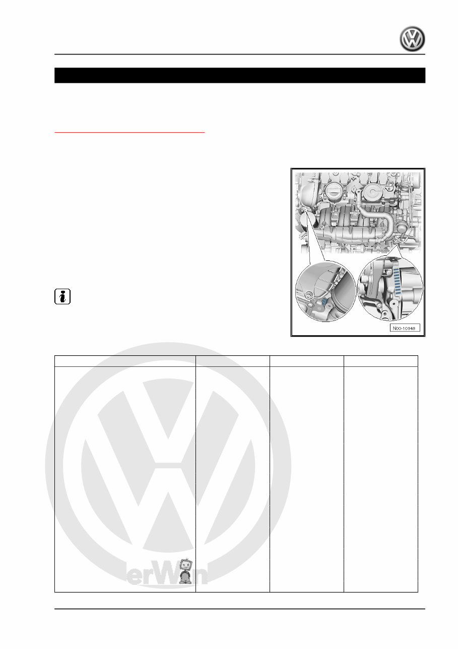
Engine number
The engine number (“code letters” and “serial number”) can be
found at the joint between the engine and gearbox.
The engine code is also stamped on the cylinder block behind the
oil filter.
In addition, there is a sticker on the right of the timing chain cover
with “engine code” and “serial number”.
The first 3 characters denote the mechanical design of the engine
and are stamped on the engine. The fourth character denotes the
performance and torque rating of the engine and depends on the
engine control unit. The four-character engine code can be found
on the identification plate as well as on the vehicle data sticker. It
can also be read from the engine control unit.
Note
Fitting locations of vehicle data sticker ⇒ Maintenance ; Booklet
36.1 ; Vehicle data sticker
Engine data
Engine code CJXB CJXC CYFB
Capacity l 1.984 1.984 1.984
Output kW at rpm 206/5100 … 6500 221/5500 … 6200 215/5400 ... 6200
Torque Nm at rpm 380/1800 … 5100 380/1800 … 5500 380/1900 ... 5300
Bore Diameter, mm 82.5 82.5 82.5
Stroke mm 92.8 92.8 92.8
Compression ratio 9.3:1 9.3:1 9.3:1
RON
98
1)
98
1)
98
1)
Ignition/injection system FSI
MPI
FSI
MPI
FSI
MPI
Exhaust gas recirculation no no no
Exhaust gas temperature regulation no no no
Turbocharging/supercharging Turbocharger Turbocharger Turbocharger
Knock control yes yes yes
Charge air cooler yes yes yes
Lambda control yes yes yes
Camshaft timing control yes yes yes
Variable intake manifold yes yes yes
Secondary air system no no no
Valves per cylinder 4 4 4
Firing order 1-3-4-2 1-3-4-2 1-3-4-2
Cylinder shut-off no no no
Golf 2013 ➤ , Golf 2015 ➤ , Golf Variant 2014 ➤ , Golf Variant 2015 ➤
4-cyl. direct injection engine (2.0 l, 4 V, turbocharger, chain drive, generation III) Volkswagen R GmbH
- Edition 07.2015
1. Identification 1
P
r o t e
c t e
d
b
y
c
o
p
y r i g
h t .
C
o
p
y i n
g
f o
r
p
r i v
a
t
e
o
r
c
o
m
m
e
r
c
i
a
l
p
u
r
p
o
s
e
s
,
i
n
p
a
r
t
o
r
i
n
wh
o
l
e
,
i
s
n
o
t
p
e
r
m
i t t e
d
u
n
l e
s
s
a
u t h
o
r i s
e
d
b
y
V
o l k
s
w
a
g
e
n
A
G
.
V
o l k s
w
a
g
e
n
A
G
d
o
e
s
n
o t
g
u
a r a
n t e
e
o
r
a
c
c
e
p
t
a
n
y
l i a
b
i l i t
y
w
i t
h
r
e
s
p
e
c
t
t
o
t
h
e
c
o
r
r
e
c
t
n
e
s
s
o
f
i
n
f
o
r
m
a
t i
o
n
i n
t
h
i s
d
o
c
u
m
e
n
t .
C
o
p
y r i g
h t
b
y
V
o l k
s
w
a
g
e
n
A
G
.
Engine code CJXB CJXC CYFB
•
1)
Unleaded petrol RON 95 can also be used, but results in
reduced power
Golf 2013 ➤ , Golf 2015 ➤ , Golf Variant 2014 ➤ , Golf Variant 2015 ➤
4-cyl. direct injection engine (2.0 l, 4 V, turbocharger, chain drive, generation III) Volkswagen R GmbH
- Edition 07.2015
2 Rep. gr.00 - Technical data
You're Reading a Preview
What's Included?
Lifetime Access
Access PDF Contents & Bookmarks
Print one or all pages of your manual
Add to Cart
$48.99
$63.99