P rote cte d b y c o p yrig ht. C o p yin g fo r p riv a t e o r c o m m e r c i a l p u r p o s e s , i n p a r t o r i n wh o l e , i s n o t p e r m itte d u n le s s a uth o ris e d b y V olk s w a g e n A G . V olks w a g e n A G d o e s n ot g u ara nte e o r a c c e p t a n y lia b ilit y w it h r e s p e c t t o t h e c o r r e c t n e s s o f i n f o r m a ti o n in t h is d o c u m e n t. C o p yrig ht b y V olk s w a g e n A G . Workshop Manual Golf 1998 ➤ Bora 1999 ➤ 4-cyl. injection engine (2.0 ltr.), mechanics Engine ID APK AQY AZH Edition 07.2004 Service Service Department. Technical Information
P rote cte d b y c o p yrig ht. C o p yin g fo r p riv a t e o r c o m m e r c i a l p u r p o s e s , i n p a r t o r i n wh o l e , i s n o t p e r m itte d u n le s s a uth o ris e d b y V olk s w a g e n A G . V olks w a g e n A G d o e s n ot g u ara nte e o r a c c e p t a n y lia b ilit y w it h r e s p e c t t o t h e c o r r e c t n e s s o f i n f o r m a ti o n in t h is d o c u m e n t. C o p yrig ht b y V olk s w a g e n A G . 1 Removing and installing parts of cooling system . . . . . . . . . . . . . . . . . . . . . . . . . . . . . . . . 75 1.1 Parts of cooling system - body side . . . . . . . . . . . . . . . . . . . . . . . . . . . . . . . . . . . . . . . . . . 75 1.2 Parts of cooling system - engine side . . . . . . . . . . . . . . . . . . . . . . . . . . . . . . . . . . . . . . . . . . 77 1.3 Coolant hose schematic diagram . . . . . . . . . . . . . . . . . . . . . . . . . . . . . . . . . . . . . . . . . . . . 78 1.4 Draining and filling coolant . . . . . . . . . . . . . . . . . . . . . . . . . . . . . . . . . . . . . . . . . . . . . . . . . . 81 1.5 Removing and installing radiator . . . . . . . . . . . . . . . . . . . . . . . . . . . . . . . . . . . . . . . . . . . . 83 1.6 Removing and installing coolant pump . . . . . . . . . . . . . . . . . . . . . . . . . . . . . . . . . . . . . . . . 85 1.7 Removing and installing thermostat . . . . . . . . . . . . . . . . . . . . . . . . . . . . . . . . . . . . . . . . . . 86 20 - Fuel supply system . . . . . . . . . . . . . . . . . . . . . . . . . . . . . . . . . . . . . . . . . . . . . . . . 89 1 Removing and installing parts of fuel supply system . . . . . . . . . . . . . . . . . . . . . . . . . . . . . . 89 1.1 Removing and installing fuel tank with attachments and fuel filter . . . . . . . . . . . . . . . . . . . . 89 1.2 Removing, installing and checking suction jet pump: vehicles with four-wheel drive . . . . . . 94 1.3 Safety precautions when working on fuel supply system . . . . . . . . . . . . . . . . . . . . . . . . . . 97 1.4 Rules for cleanliness . . . . . . . . . . . . . . . . . . . . . . . . . . . . . . . . . . . . . . . . . . . . . . . . . . . . . . 98 1.5 Removing and installing fuel delivery unit . . . . . . . . . . . . . . . . . . . . . . . . . . . . . . . . . . . . . . 98 1.6 Removing and installing fuel gauge sender G . . . . . . . . . . . . . . . . . . . . . . . . . . . . . . . . . . 101 1.7 Removing and installing fuel tank . . . . . . . . . . . . . . . . . . . . . . . . . . . . . . . . . . . . . . . . . . . . 101 1.8 Crash fuel shut-off . . . . . . . . . . . . . . . . . . . . . . . . . . . . . . . . . . . . . . . . . . . . . . . . . . . . . . . . 103 1.9 Checking fuel pump G23 . . . . . . . . . . . . . . . . . . . . . . . . . . . . . . . . . . . . . . . . . . . . . . . . . . 103 2 Activated charcoal filter system . . . . . . . . . . . . . . . . . . . . . . . . . . . . . . . . . . . . . . . . . . . . . . 110 2.1 Function . . . . . . . . . . . . . . . . . . . . . . . . . . . . . . . . . . . . . . . . . . . . . . . . . . . . . . . . . . . . . . . . 110 2.2 Repairing parts of activated charcoal filter system . . . . . . . . . . . . . . . . . . . . . . . . . . . . . . . . 110 2.3 Checking solenoid valve 1 for activated charcoal filter system . . . . . . . . . . . . . . . . . . . . . . 111 2.4 Checking fuel tank venting . . . . . . . . . . . . . . . . . . . . . . . . . . . . . . . . . . . . . . . . . . . . . . . . . . 114 3 Checking electronic power control (EPC) . . . . . . . . . . . . . . . . . . . . . . . . . . . . . . . . . . . . . . 116 3.1 Function of EPC system . . . . . . . . . . . . . . . . . . . . . . . . . . . . . . . . . . . . . . . . . . . . . . . . . . . . 116 3.2 Checking accelerator pedal position sender . . . . . . . . . . . . . . . . . . . . . . . . . . . . . . . . . . . . 117 4 Accelerator mechanism . . . . . . . . . . . . . . . . . . . . . . . . . . . . . . . . . . . . . . . . . . . . . . . . . . . . 121 4.1 Repairing accelerator mechanism . . . . . . . . . . . . . . . . . . . . . . . . . . . . . . . . . . . . . . . . . . . . 121 4.2 Adjusting throttle cable . . . . . . . . . . . . . . . . . . . . . . . . . . . . . . . . . . . . . . . . . . . . . . . . . . . . 121 26 - Exhaust system . . . . . . . . . . . . . . . . . . . . . . . . . . . . . . . . . . . . . . . . . . . . . . . . . . 123 1 Removing and installing parts of exhaust system . . . . . . . . . . . . . . . . . . . . . . . . . . . . . . . . 123 1.1 Vehicles with front-wheel drive . . . . . . . . . . . . . . . . . . . . . . . . . . . . . . . . . . . . . . . . . . . . . . 123 1.2 Vehicles with four-wheel drive . . . . . . . . . . . . . . . . . . . . . . . . . . . . . . . . . . . . . . . . . . . . . . 126 1.3 Checking catalytic converter . . . . . . . . . . . . . . . . . . . . . . . . . . . . . . . . . . . . . . . . . . . . . . . . 129 2 Secondary air system . . . . . . . . . . . . . . . . . . . . . . . . . . . . . . . . . . . . . . . . . . . . . . . . . . . . . . 132 2.1 Function . . . . . . . . . . . . . . . . . . . . . . . . . . . . . . . . . . . . . . . . . . . . . . . . . . . . . . . . . . . . . . . . 132 2.2 Removing and installing parts of secondary air system . . . . . . . . . . . . . . . . . . . . . . . . . . . . 132 2.3 Checking combination valve . . . . . . . . . . . . . . . . . . . . . . . . . . . . . . . . . . . . . . . . . . . . . . . . 134 2.4 Checking secondary air pump motor . . . . . . . . . . . . . . . . . . . . . . . . . . . . . . . . . . . . . . . . . . 135 2.5 Checking secondary air inlet valve N112 . . . . . . . . . . . . . . . . . . . . . . . . . . . . . . . . . . . . . . 136 Golf 1998 ➤ , Bora 1999 ➤ 4-cyl. injection engine (2.0 ltr.), mechanics - Edition 07.2004 ii Contents
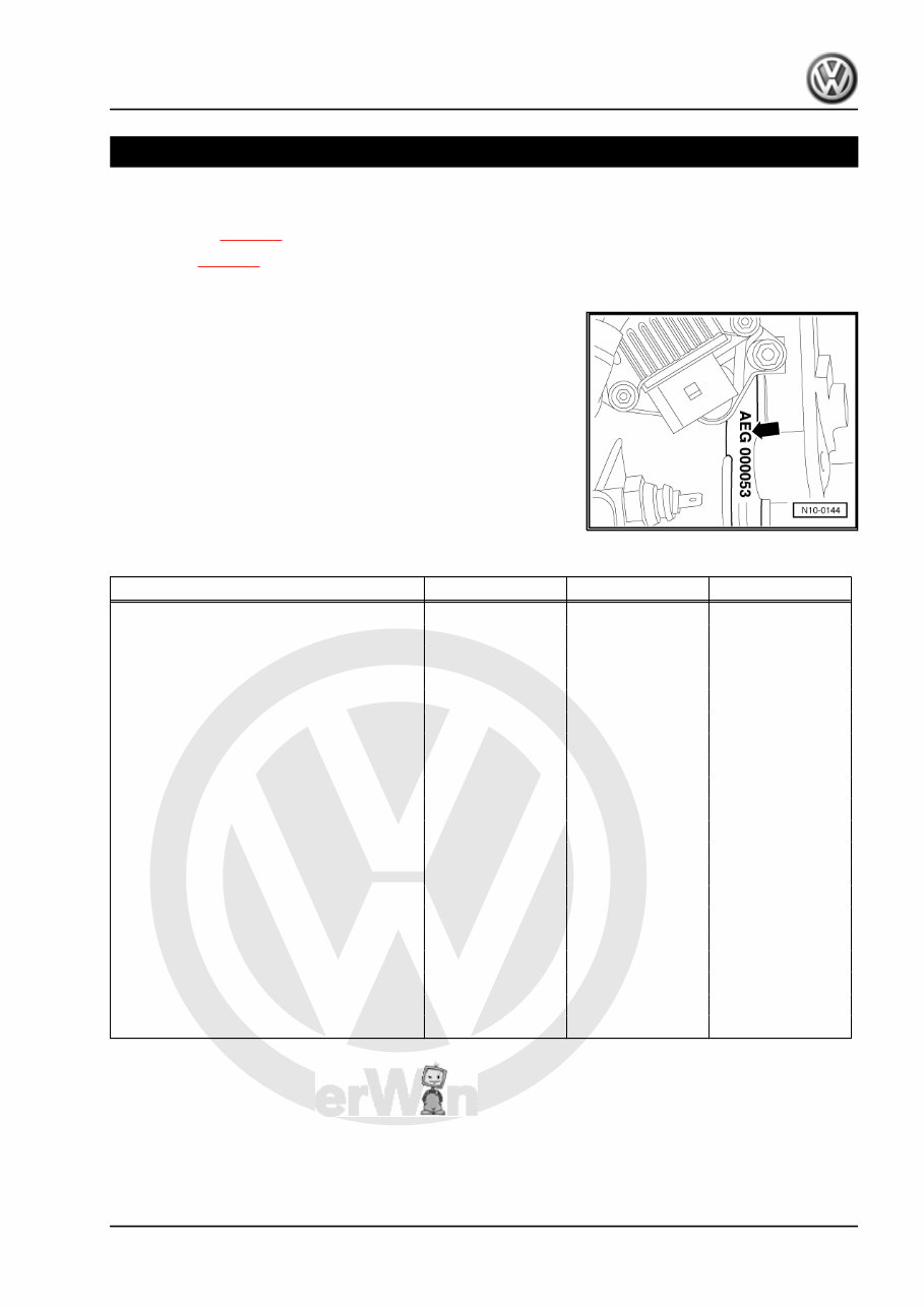
P rote cte d b y c o p yrig ht. C o p yin g fo r p riv a t e o r c o m m e r c i a l p u r p o s e s , i n p a r t o r i n wh o l e , i s n o t p e r m itte d u n le s s a uth o ris e d b y V olk s w a g e n A G . V olks w a g e n A G d o e s n ot g u ara nte e o r a c c e p t a n y lia b ilit y w it h r e s p e c t t o t h e c o r r e c t n e s s o f i n f o r m a ti o n in t h is d o c u m e n t. C o p yrig ht b y V olk s w a g e n A G . 00 – Technical data 1 Technical data Engine number ⇒ page 1 Engine data ⇒ page 1 1.1 Engine number The engine number (“engine code” and “serial number”) can be found at the front on the joint between engine and gearbox. The engine number consists of up to nine characters (alphanu‐ meric). The first part (maximum 3 characters) makes up the “engine code”, and the second part (6 characters), the “serial number”. If more than 999,999 engines with the same engine code are produced, the first of the six characters is replaced with a letter. In addition, there is a sticker on the toothed belt guard with “engine code” and “serial number”. The engine code is also included on the vehicle data sticker. 1.2 Engine data Engine code APK AQY AZH Manufactured 11.98 ▸ 11.98 ▸ 09.00 ▸ Emissions fulfil MVEG II D4 standard EU4 standard Capacity l 2,0 2,0 2,0 Output kW at rpm 85/5200 85/5200 85/5400 Torque Nm at rpm 170/2400 170/2400 170/2400 Bore ∅ mm 82,5 82,5 82,5 Stroke mm 92,8 92,8 92,8 Compression ratio 10,5 10,5 10,5 RON min. 95 unleaded 95 unleaded 95 unleaded Injection, ignition Motronic 5.9.2 Motronic 5.9.2 Motronic ME7.5 Knock control yes yes 2 knock sensors Self-diagnosis yes yes yes Lambda regulation yes yes 2 probes Catalytic converter yes yes yes Exhaust gas recirculation no no no Turbocharging/supercharging no no no Secondary air system no yes yes Variable intake manifold no no no Variable valve timing no no no Electronic power control no no yes Golf 1998 ➤ , Bora 1999 ➤ 4-cyl. injection engine (2.0 ltr.), mechanics - Edition 07.2004 1. Technical data 1
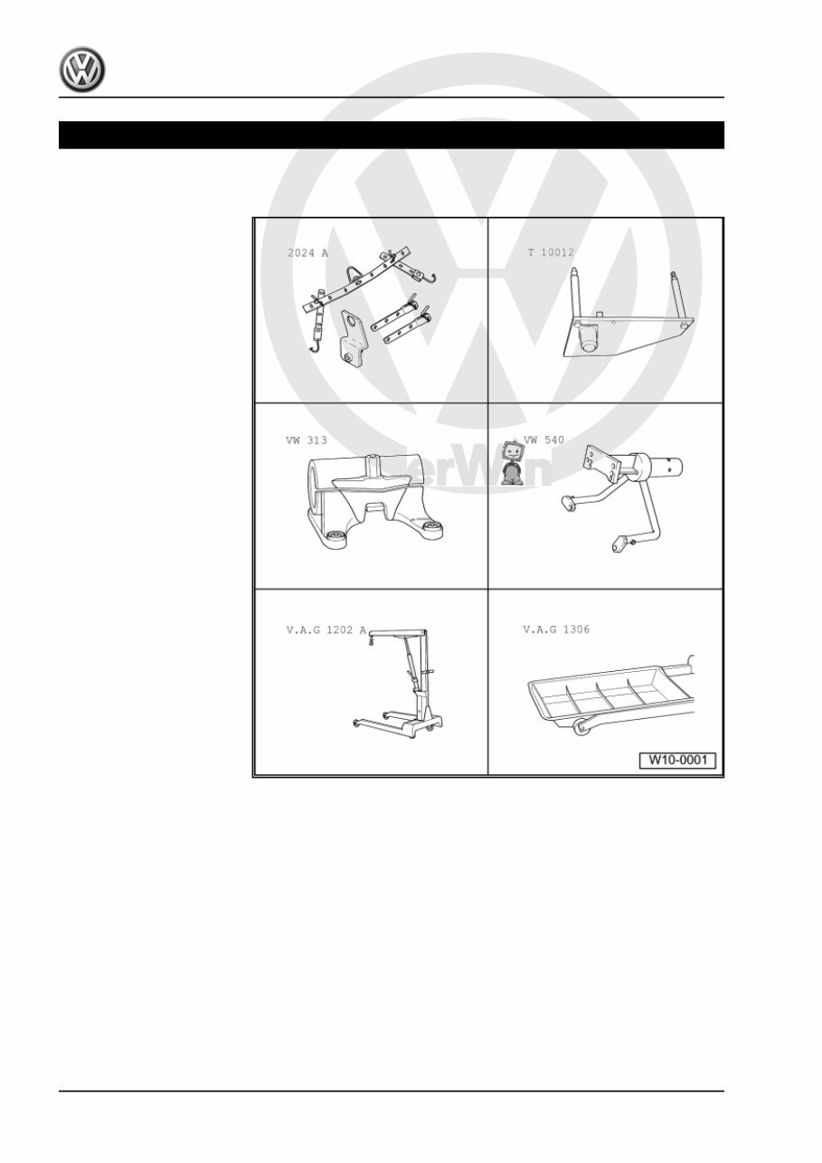
P rote cte d b y c o p yrig ht. C o p yin g fo r p riv a t e o r c o m m e r c i a l p u r p o s e s , i n p a r t o r i n wh o l e , i s n o t p e r m itte d u n le s s a uth o ris e d b y V olk s w a g e n A G . V olks w a g e n A G d o e s n ot g u ara nte e o r a c c e p t a n y lia b ilit y w it h r e s p e c t t o t h e c o r r e c t n e s s o f i n f o r m a ti o n in t h is d o c u m e n t. C o p yrig ht b y V olk s w a g e n A G . 10 – Removing and installing engine 1 Removing and installing engine Special tools and workshop equipment required ♦ Lifting tackle -2024 A- ♦ Engine bracket -T10012- ♦ Support clamp -VW 313- ♦ Engine and gearbox stand - VW 540- ♦ Workshop hoist -V.A.G 1202 A- or workshop hoist - VAS 6100- ♦ Drip tray -V.A.G 1306- or drip tray for workshop hoist -VAS 6208- Golf 1998 ➤ , Bora 1999 ➤ 4-cyl. injection engine (2.0 ltr.), mechanics - Edition 07.2004 2 Rep. Gr.10 - Removing and installing engine
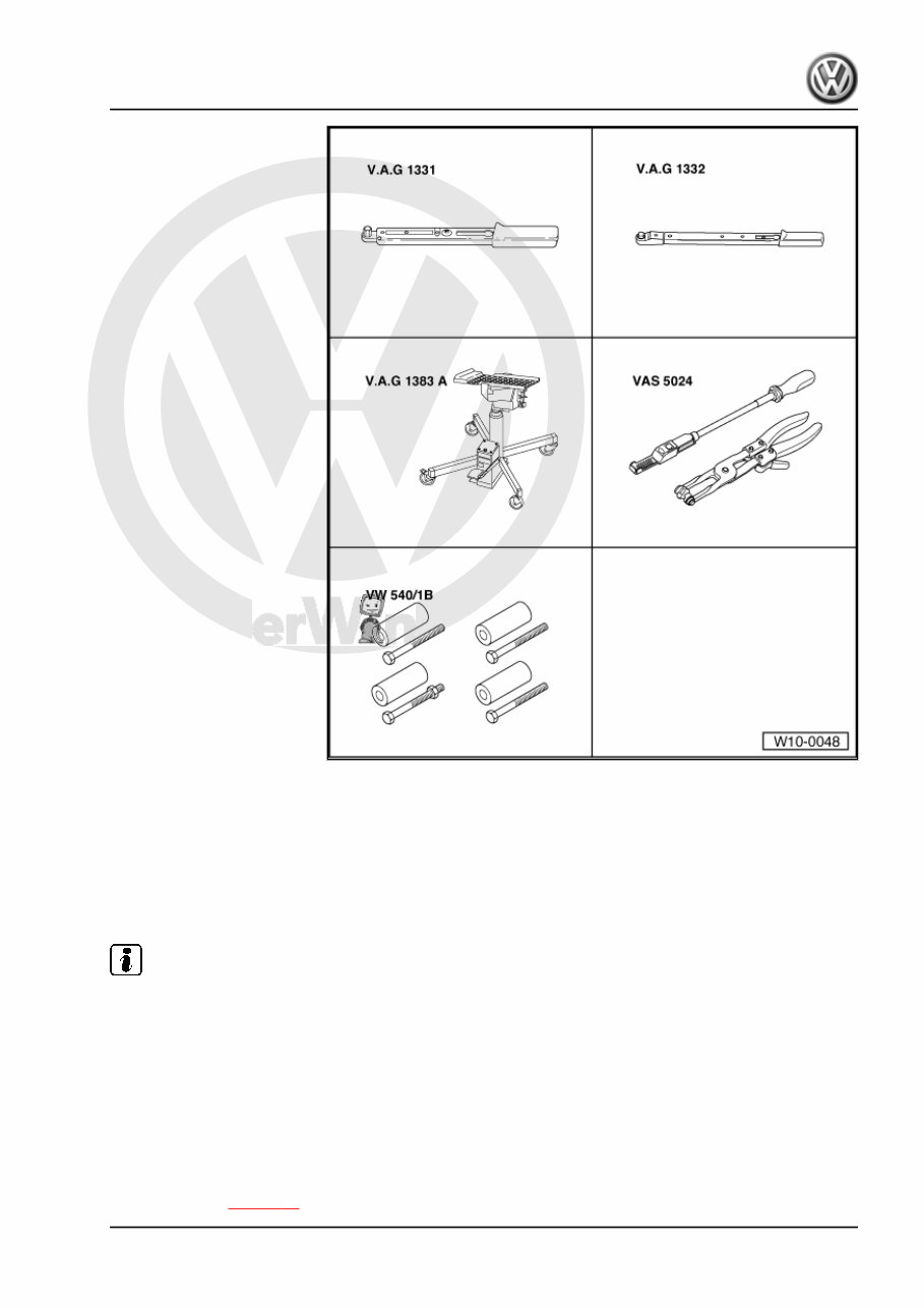
P rote cte d b y c o p yrig ht. C o p yin g fo r p riv a t e o r c o m m e r c i a l p u r p o s e s , i n p a r t o r i n wh o l e , i s n o t p e r m itte d u n le s s a uth o ris e d b y V olk s w a g e n A G . V olks w a g e n A G d o e s n ot g u ara nte e o r a c c e p t a n y lia b ilit y w it h r e s p e c t t o t h e c o r r e c t n e s s o f i n f o r m a ti o n in t h is d o c u m e n t. C o p yrig ht b y V olk s w a g e n A G . ♦ Torque wrench -V.A.G 1331- (5..50 Nm) ♦ Torque wrench -V.A.G 1332- (40...200 Nm) ♦ Engine and gearbox jack - V.A.G 1383 A- ♦ Spring-type clip pliers -VAS 5024- ♦ Engine and gearbox sup‐ port supplement -VW 540/1 B- ♦ Step ladder -VAS 5085- Not illustrated: ♦ Grease -G 000 100- (vehicles with manual gearbox) ♦ Bolt M10×25 / 8.8 ♦ Cable ties 1.1 Notes on removing Note Before carrying out further work, disconnect battery earth strap. First check whether a coded radio is fitted. Obtain radio code first if necessary. – The engine is removed downwards together with the gearbox. – All cable ties which are opened or cut through when engine is removed must be replaced in the same position when engine is installed. – With the ignition switched off, disconnect battery earth strap. – Remove engine cover. – Drain coolant ⇒ page 81 . Golf 1998 ➤ , Bora 1999 ➤ 4-cyl. injection engine (2.0 ltr.), mechanics - Edition 07.2004 1. Removing and installing engine 3
P rote cte d b y c o p yrig ht. C o p yin g fo r p riv a t e o r c o m m e r c i a l p u r p o s e s , i n p a r t o r i n wh o l e , i s n o t p e r m itte d u n le s s a uth o ris e d b y V olk s w a g e n A G . V olks w a g e n A G d o e s n ot g u ara nte e o r a c c e p t a n y lia b ilit y w it h r e s p e c t t o t h e c o r r e c t n e s s o f i n f o r m a ti o n in t h is d o c u m e n t. C o p yrig ht b y V olk s w a g e n A G . – Remove battery and battery retainer. Golf 1998 ➤ , Bora 1999 ➤ 4-cyl. injection engine (2.0 ltr.), mechanics - Edition 07.2004 4 Rep. Gr.10 - Removing and installing engine
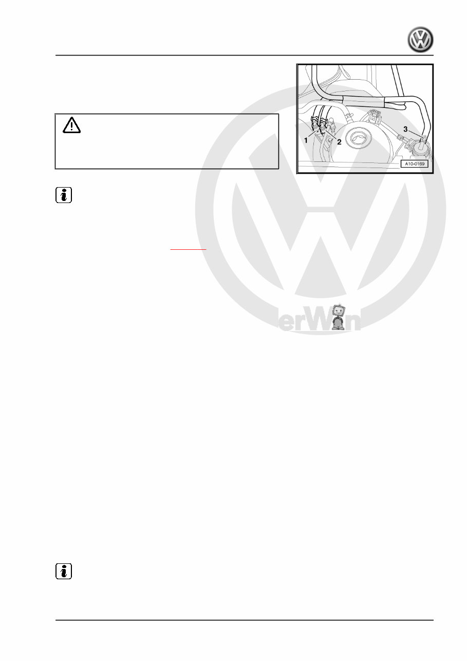
P rote cte d b y c o p yrig ht. C o p yin g fo r p riv a t e o r c o m m e r c i a l p u r p o s e s , i n p a r t o r i n wh o l e , i s n o t p e r m itte d u n le s s a uth o ris e d b y V olk s w a g e n A G . V olks w a g e n A G d o e s n ot g u ara nte e o r a c c e p t a n y lia b ilit y w it h r e s p e c t t o t h e c o r r e c t n e s s o f i n f o r m a ti o n in t h is d o c u m e n t. C o p yrig ht b y V olk s w a g e n A G . – Pull off supply hose -1- (with white marking) and return hose -2- (with blue marking) and catch fuel which escapes with a cloth. – Pull hose -3- off activated charcoal filter system solenoid valve 1 -N80- . WARNING Fuel system is under pressure! Before opening the system place a cloth around the connection. Then release pressure by carefully loosening the connection. Note Press buttons on hose couplings to do this. – Seal lines so that fuel system is not contaminated by dirt. – Observe rules for cleanliness ⇒ page 98 . – Pull vacuum and breather hoses off engine. – Remove noise insulation tray. – Detach connectors from the following components: ♦ Ignition transformer -N152- ♦ Hall sender -G40- ♦ Injector for cylinder 1 -N30- ♦ Injector for cylinder 2 -N31- ♦ Injector for cylinder 3 -N32- ♦ Injector for cylinder 4 -N33- ♦ Coolant temperature sender -G62- ♦ Engine speed sender -G28- ♦ Oil level and oil temperature gauge -G266- ♦ Knock sensor 1 -G61- ♦ Knock sensor 2 -G66- ♦ Secondary air pump motor -V101- ♦ Oil pressure switch -F1- ♦ Air mass meter -G70- ♦ Throttle valve control module -J338- ♦ If necessary A/C system shutoff thermal switch -F163- – Remove intake hose between air mass meter -G70- and throt‐ tle valve module -J338- ⇒ Rep. Gr. 24 . – Remove air cleaner. – Remove upper part of intake manifold: ⇒ Rep. Gr. 24 . Note Seal intake ports in the lower part of intake manifold using a clean cloth. Golf 1998 ➤ , Bora 1999 ➤ 4-cyl. injection engine (2.0 ltr.), mechanics - Edition 07.2004 1. Removing and installing engine 5
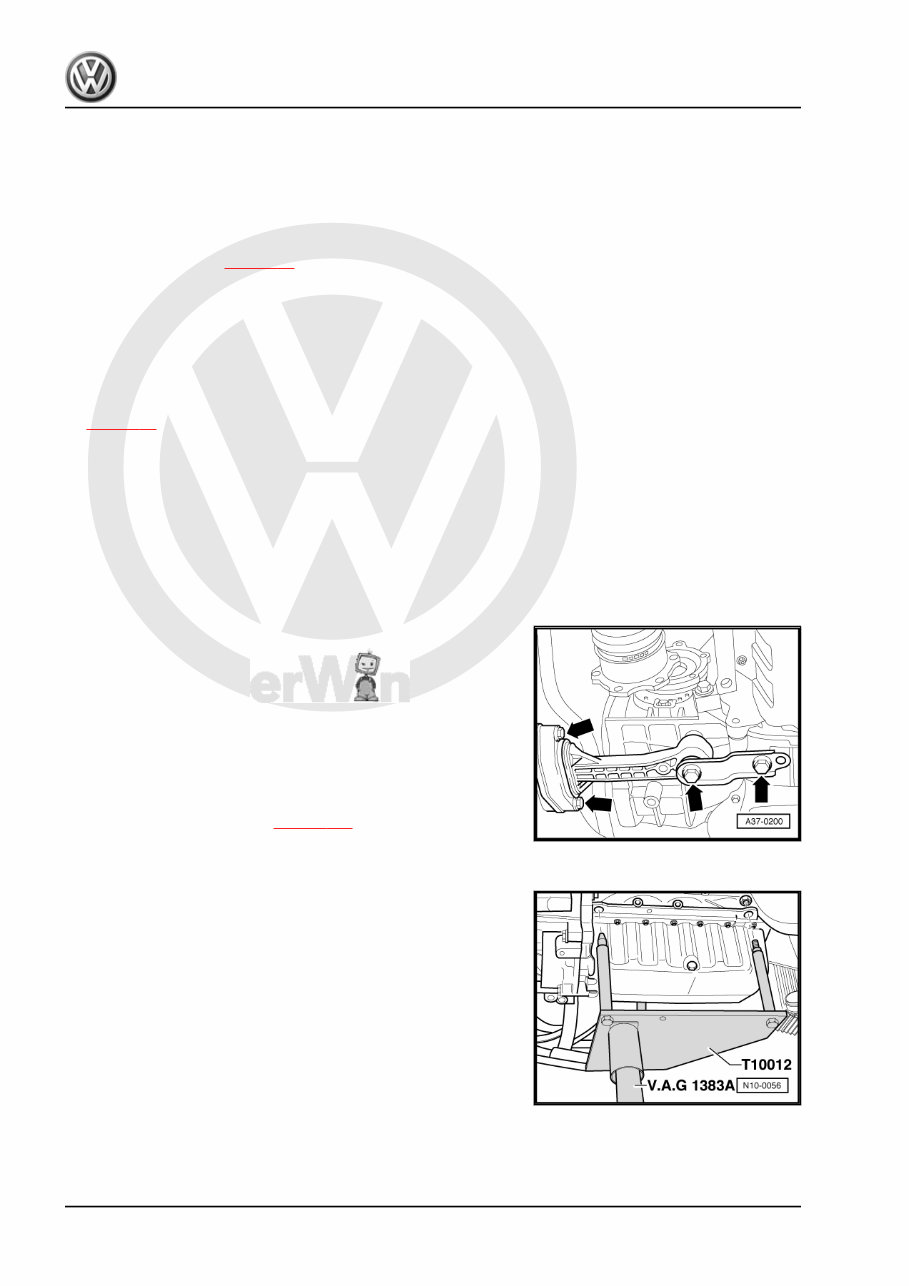
P rote cte d b y c o p yrig ht. C o p yin g fo r p riv a t e o r c o m m e r c i a l p u r p o s e s , i n p a r t o r i n wh o l e , i s n o t p e r m itte d u n le s s a uth o ris e d b y V olk s w a g e n A G . V olks w a g e n A G d o e s n ot g u ara nte e o r a c c e p t a n y lia b ilit y w it h r e s p e c t t o t h e c o r r e c t n e s s o f i n f o r m a ti o n in t h is d o c u m e n t. C o p yrig ht b y V olk s w a g e n A G . – Unbolt selector mechanism from gearbox: ⇒ Rep. Gr. 34 . – Remove hydraulic clutch slave cylinder: ⇒ Rep. Gr. 30 . Vehicles with automatic gearbox: – Remove selector lever cable from gearbox: ⇒ Rep. Gr. 37 . Continuation for all vehicles: – Remove poly V-belt ⇒ page 17 . – Remove securing clamps for power steering pressure line. – Unbolt power steering vane pump from bracket and place to one side, hoses remain connected: ⇒ Rep. Gr. 48 . Vehicles with air conditioning: – Remove air conditioner compressor. – Observe additional information and installation work ⇒ page 11 . Continuation for all vehicles: – Remove inter-connecting, coolant, vacuum and intake hoses on engine. – Remove secondary air pump and bracket. – Disconnect all electric wires from gearbox, alternator and starter and lay to side. – Pull off or disconnect all other electrical connections as nec‐ essary from engine and lay clear. – Disconnect pendulum support -arrows-. – Remove inner right constant velocity joint protective cap from engine. Vehicles with four-wheel drive: – Separate front propshaft from gearbox: ⇒ Rep. Gr. 39 . Continuation for all vehicles: – Remove right-hand drive shaft and unbolt left-hand drive shaft from gearbox: ⇒ Rep. Gr. 40 . – Remove front exhaust pipe ⇒ page 123 . – Insert engine bracket -T10012- in engine and gearbox jack - V.A.G 1383 A- . – Fit engine bracket -T10012- to front of cylinder block with M10x25/ 8.8 bolt. – Tighten securing nut exhaust side by hand. – Lift engine and gearbox slightly using engine and gearbox jack -V.A.G 1383 A- . Golf 1998 ➤ , Bora 1999 ➤ 4-cyl. injection engine (2.0 ltr.), mechanics - Edition 07.2004 6 Rep. Gr.10 - Removing and installing engine
You're Reading a Preview
What's Included?
Lifetime Access
Fast Download Speeds
Online & Offline Access
Access PDF Contents & Bookmarks
Full Search Facility
Print one or all pages of your manual
$31.99
VW Volkswagen Bora 1998 1999 2000 Workshop Service Manual R
The VW Volkswagen Bora 1998 1999 2000 Workshop Service Manual for Repair is an essential resource for both professional mechanics and DIY enthusiasts. It provides comprehensive data, characteristics, instructions, and methodology for performing repair interventions on the vehicle and its components. This .PDF manual includes special notes, important points, service data, precautions, and detailed, comprehensive step-by-step procedures, explanations, and pictorial diagrams from bumper to bumper. It is designed for easy viewing on any computer, with the ability to zoom and print. The manual covers adjustment and repair operations, including reference to service tool numbers and wear limits. It also contains general descriptions, diagnosis, testing, adjustments, removal, installation, disassembly, and assembly procedures for the systems and components. The manual is supported by photographs, notes, drawings, schematics, exploded and sectional drawings, and valuable reference data for adjustment values. It is important to strictly observe all accident prevention guidelines and use only genuine VW Volkswagen Bora 1998 1999 2000 parts as listed in the parts catalogue. The manual outlines procedures for servicing and repairing vehicles using safe, effective methods, and contains many notes, cautions, and warnings to ensure safety and prevent damage to the vehicle. To maximize the life of your VW Volkswagen Bora 1998 1999 2000, it is crucial to follow the maintenance requirements, investigate and rectify problems promptly, use approved lubricants, and keep complete records of all maintenance and repairs. This manual is designed primarily for use by trained technicians in a properly equipped workshop, but it contains enough detail and basic information to be useful to owners who desire to perform their own basic maintenance and repair work. A basic knowledge of mechanics, including the proper use of tools and workshop procedures, is necessary to carry out maintenance and repair work satisfactorily.
ABS for VW Volkswagen Bora 1998 1999 2000
Air Bag System for VW Volkswagen Bora 1998 1999 2000
Air Conditioning System for VW Volkswagen Bora 1998 1999 2000
Appendix for VW Volkswagen Bora 1998 1999 2000
Battery, Starter, Alternator for VW Volkswagen Bora 1998 1999 2000
Body Electrical Control System for VW Volkswagen Bora 1998 1999 2000
Body Structure for VW Volkswagen Bora 1998 1999 2000
Brake Control System and Diagnosis for VW Volkswagen Bora 1998 1999 2000
Brakes for VW Volkswagen Bora 1998 1999 2000
Charging System for VW Volkswagen Bora 1998 1999 2000
Clutch for VW Volkswagen Bora 1998 1999 2000
Control systems for VW Volkswagen Bora 1998 1999 2000
Cooling System for VW Volkswagen Bora 1998 1999 2000
Crankshaft for VW Volkswagen Bora 1998 1999 2000
Cruise Control System for VW Volkswagen Bora 1998 1999 2000
Cylinder Head Removal and Installation for VW Volkswagen Bora 1998 1999 2000
Differential for VW Volkswagen Bora 1998 1999 2000
Drive Shafts and Axle for VW Volkswagen Bora 1998 1999 2000
Driveline and Axle for VW Volkswagen Bora 1998 1999 2000
Electrical System for VW Volkswagen Bora 1998 1999 2000
Emission Control Devices for VW Volkswagen Bora 1998 1999 2000
Engine Cooling System for VW Volkswagen Bora 1998 1999 2000
Engine Electrical Devices for VW Volkswagen Bora 1998 1999 2000
Engine Lubrication System for VW Volkswagen Bora 1998 1999 2000
Engine Mechanical for VW Volkswagen Bora 1998 1999 2000
Engine Removal and Installation for VW Volkswagen Bora 1998 1999 2000
Engine Top End for VW Volkswagen Bora 1998 1999 2000
Exhaust System for VW Volkswagen Bora 1998 1999 2000
Exterior Trim for VW Volkswagen Bora 1998 1999 2000
Final Drive for VW Volkswagen Bora 1998 1999 2000
Frame for VW Volkswagen Bora 1998 1999 2000
Front Axle Differential for VW Volkswagen Bora 1998 1999 2000
Front Brakes for VW Volkswagen Bora 1998 1999 2000
Front Suspension for VW Volkswagen Bora 1998 1999 2000
Fuel Injection for VW Volkswagen Bora 1998 1999 2000
Fuel System for VW Volkswagen Bora 1998 1999 2000
Fuel Tank and Fuel Pump for VW Volkswagen Bora 1998 1999 2000
General Data and Maintenance for VW Volkswagen Bora 1998 1999 2000
Heater and Ventilation for VW Volkswagen Bora 1998 1999 2000
Heating and Air-conditioning for VW Volkswagen Bora 1998 1999 2000
Ignition System for VW Volkswagen Bora 1998 1999 2000
Lighting Systems for VW Volkswagen Bora 1998 1999 2000
Lights Electrical System for VW Volkswagen Bora 1998 1999 2000
Lubrication System for VW Volkswagen Bora 1998 1999 2000
Maintenance and Lubrication for VW Volkswagen Bora 1998 1999 2000
Manual Transmission for VW Volkswagen Bora 1998 1999 2000
Parking Brake for VW Volkswagen Bora 1998 1999 2000
Periodic Maintenance for VW Volkswagen Bora 1998 1999 2000
Power Assisted Steering System for VW Volkswagen Bora 1998 1999 2000
Propeller Shafts for VW Volkswagen Bora 1998 1999 2000
Radiator and Cooling System for VW Volkswagen Bora 1998 1999 2000
Rear Axle Differential for VW Volkswagen Bora 1998 1999 2000
Rear Brakes for VW Volkswagen Bora 1998 1999 2000
Rear Suspension for VW Volkswagen Bora 1998 1999 2000
Restraint for VW Volkswagen Bora 1998 1999 2000
Starting System for VW Volkswagen Bora 1998 1999 2000
Steering and Wheel Alignment for VW Volkswagen Bora 1998 1999 2000
Steering Wheel and Column for VW Volkswagen Bora 1998 1999 2000
Suspension Steering and Brakes for VW Volkswagen Bora 1998 1999 2000
Switches for VW Volkswagen Bora 1998 1999 2000
Symptoms and Field Observations for VW Volkswagen Bora 1998 1999 2000
Transfer Case for VW Volkswagen Bora 1998 1999 2000
Transmission and Transaxle for VW Volkswagen Bora 1998 1999 2000
Vehicle Identification and VIN for VW Volkswagen Bora 1998 1999 2000
Wheels and Tires for VW Volkswagen Bora 1998 1999 2000
Wipers and Washers for VW Volkswagen Bora 1998 1999 2000
Reviews
Q&A
Recently Viewed
5,521,897Happy Clients
2,594,462eManuals
1,120,453Trusted Sellers
15Years in Business
Price:
Actual Price:
VW Volkswagen Bora 1998 1999 2000 Workshop Service Manual R