

VW VOLKSWAGEN BEETLE 1300 Workshop Service Repair Manual
What's Included?
Fast Download Speeds
Offline Viewing
Access Contents & Bookmarks
Full Search Facility
Print one or all pages of your manual
Beetle &
Automotive
Repair
Manua
by Ken Freund,
Mike Stubblefield,
and John H Haynes
Mernbr of the Guild of Mobnng Wrrters
Models covered:
All VW Beetles and Karmann Ghias
Does not include diesel engrne information
Haynes Publishing Group
Sparkford Nr Yeovil
Somerset BA22 7JJ England
Haynes North America, Inc
861 Lawrence Drive
Newbury Park
California 91320 USA
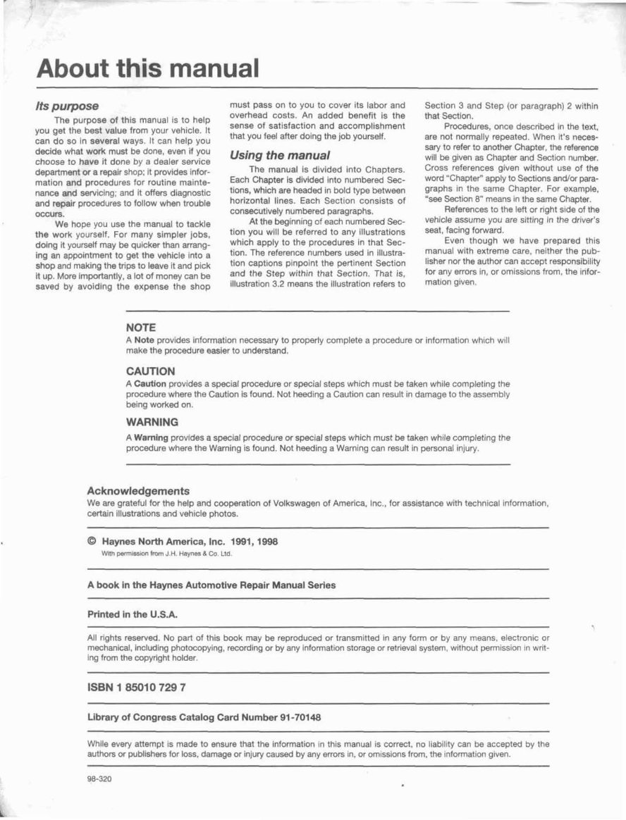
About this manual
Its purpose
The purpose of this manual is to help
you get the best value from your vahicle. It
can do so in several ways. It can help you
decide what work must be done, even if you
choose to have it done by a dealer service
department or a repair shop; it provides Infor-
mation and procedures for routine mainte-
nance and servicing; and it offers diagnostic
and repalr procedures to follow when trouble
occurs.
We hope you use the manual to tackle
the work yourself. For many simpler jobs,
doing it yourself may be quicker than arrang-
Ing an appointment to get the vehicle Into a
shop and making the trips to leave it and pick
It up. More Importantly, a lot of money can be!
saved by avoiding the expense the shop
must pass on to you to cover rts labor and
overhead costs. An added benefit is the
sense of satisfaction and accomplishment
that you feel after doing the job yourself.
Using the manual
The manual Is divided into Chapters.
Each Chapter Is dMded Into numbered Sec-
tions, which are headed in bold type between
horizontal lines. Each Sect~on consists of
consecutrvely numbered paragraphs.
At the b%glnnmg of each numbered Sec-
tion you will be referred to any illustrations
which apply to the procedures in that Sec-
tion. The reference numbers used In illustra-
tlon captlons pinpoint the pertinent Section
and the Step within that Sectfon. That is,
Illustretton 3.2 means the illustration refers to
Section 3 and Shp (or paragraph) 2 within
that Section.
Procedures. once described in the text,
are not normally repeated. When it's neces-
sary to refer to anothw Chaptw, the m c e
will be given as Chapter and Section numbr.
Cross references glven without use of the
word "Chapter" apply to Sections andror para-
graphs in the same Chapter. For example,
"see Section 8" means in the same Chapter.
References to the left or r~ght side of the
vehjcle assume you are sitting In the driver's
seat, facing forward.
Even though we have prepared this
manual with extreme care. neither the pub-
lisher nor the author can accept responsibility
for any errors In, ox omiss~ons from, the ~nfor-
mation glven.
NOTE
A Nata provides information necessary to properly complete a procedure or information which w~ll
make the procedure easier to understand.
CAUTION
A Cautfon provides a special procedure or special steps which must be taken while complet~ng the
procedure where the Cautlon is found. Not heeding a Caution can result in damage to the assembly
being worked on.
WARNING
A Warning provides a special pwedure or special steps which must be taken while completing the
procedure where the Warning 1s found. Not heeding a Warning can result in personal injury.
Acknowledgements
We are grateful for the help and cooperation of Volkswagen of Amer~ca, Inc., for asslstance with technical information,
certain illustrations and vehicle photos.
0 Haynes North America, Ine. 1991,1998
Wtfh mlsslon from J.H. Haynes & Co. ttd.
A book in the Haynes Automotivh Repair Manual Series
P~*inted In the U.S.A.
All rights resewed. No part af this book may be reproduced or transmitted In any form or by any means, electronic or
rnechanrcal, including photocopying, recording or by any information storage or retrieval system, without permission In writ-
ing from the mpyright holder.
Library of Congress Catalog Card Number 81 -70148
Whlle every attempt rs made to ensure that the Informd~on In this manual is correct, no liability can be accepted by the
authors or publishers for loss, damage or injury caused by any errors m, or omissions from, the information given.
98-320
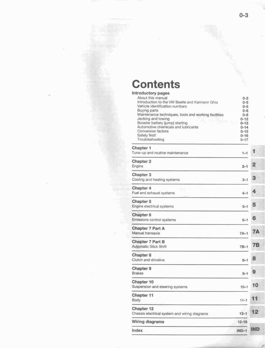
Contents
Introductory pages
About thls manual
lntrod~ct~on 10 the VW Beetle and Karmann Ghia
Vehicle identification numbers
Buying parts
Maintenance techniques, tools and worklng facilities
Jacking and towing
Booster battery (lump) starting
Automottve chemicals and lubricants
Conversion factors
Safety first?
Troubleshooting
Chapter i
Tune-up and rnuttne maintenance
Chapter 2
Engrne 2-1
Chapter 3
Cooling and heating systems 3-1
Chapter 4
Fuel and exhaust systems
Chapter 5
Engine electr~cal systems
Chapter 6
Em~ssions control systems 161
Chapter 7 Part A
Manual transaxle 74-1
Chapter 7 Part El
Automatic Stick Shift
Chapter 8
Clutch and drivellne
Chapter 9
Brakes
Chapter i Q
Suspension and steering systems 10-1 lo
Chapter 11
Body 11-1
Chapter f 2
Chassis electrical system and wlrlng diagrams
Wiring diagrams 12-1 8
Index rNB1 lFAD
! - -- A 2
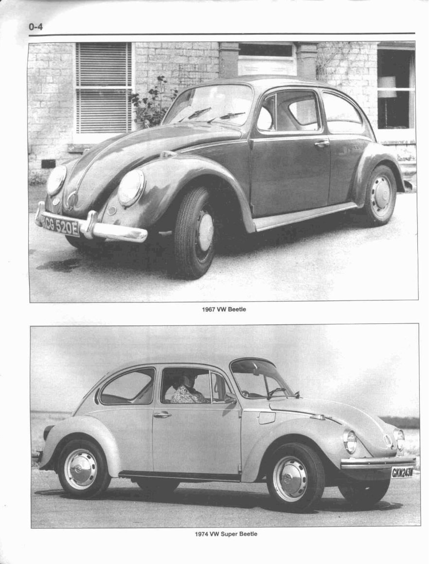
1974 VW Super Beetle
Introduction to the
Volkswagen Beetle and Karmann Ghia
)e rear susl
?ssed mer
The vehicles covered by thrs manual are axle-tyg penslon, in which the axles wlth the steering gearbox mounted to the
very sim~lar tn design. Although the Kamann are strt nbers of the suspension. front axle beam. Later models were equipped
Ghia may appear to be a completely different Later models use dtiveaxles, which are used with a rack-and-pinion style steering gear.
vehicle, it shares the same basic platform only for the transmission of power to the rear The rear suspension on a$ models is of
and components. wheels. a torsion bar des~gn, although there are sig-
The horizontally opposed, four-cyl~nder Independent suspenston, featuring tor- nlficant differences between models with
engine used in these models is equipped with sion bars, trailing arms, and telescopic shock swing axles and modeis with driveaxles (see
either a carburetor or electronic fuel ~nlection. absorbers in used on the front wheels of most Chapter 8 for more details). Telescopic shock
All models util~ze a breaker points-type igni- models. Beginning with the 1971 Super Bee- absorbers are also used at the rear.
tion system.
tle, some models were equipped w12h a All models are equipped wtth drum brakes on
The engine drtves the rear wheels MacPherson strut-type front suspension (all all four wheels, w~th the exception of later
through a 4-speed manual or 3-speed 1975 and later models were equrpped wlth model Karmann Gbias, which were equipped
semi-automatic transaxle vla independent this type of front suspension). Most models with disc brakes on the front wheels.
axles. Early models employ a swlng use a worm-and-roller type steering gear,
Vehicle identification numbers
Mod~ficat~ons are a continuing and compiled on a numerical basis, the Endrvidual
Chassis jdenfjfjation number
unpublicrzed process In vehicle manufactur- veh~cla numbers are necessary to correctly
ing. Since spare parts manuals and lists are identify the component requ~red.
Th~s very important Identification num-
ber is found in three different places: on the
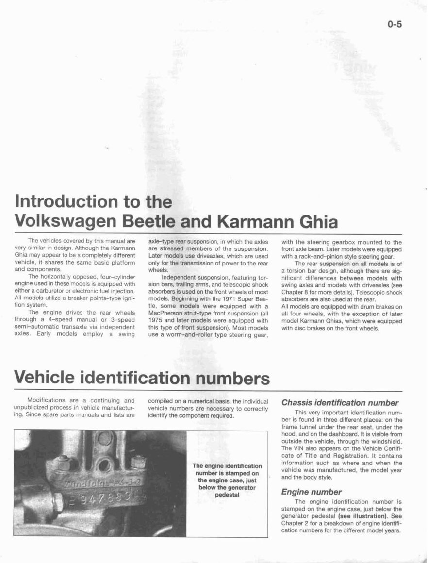
The engine idenWicatlon
number is stamped on
the engim case, just
below the generator
pedestal
frame tunnel under the rear seat, under the
hood. and on the dashboard. It IS visible from
outsida the vehicle, through the windshietd.
The VIM also appears on the Yehide Certifi-
cate of Title and Registration. It contains
information such as where and when the
vehicle was manufactured. the model year
and the body style.
Engine number
The engine identification number is
stamped on the engine case, just below the
generator pedestal (see illustration). See
Chaptw 2 for a breakdown of engine identifi-
cation numbers for the drlferent model years.
0-6
Buying parts
Replacement parts are available from
many sources, which generalry fall into one of
two categories - authorized dealer parts
departments and independent retail auto
parts stores. Our adv~ce concerning these
pans is as follows:
Retall auto parts stores: Good auto
parts stores will stock frequently needed
components which wear out relatively fast,
such as clutch components, exhaust sys-
tems, brake parts, tune-up parts, etc. these
stores often supply new or rscondit~oned
parts an an exchange basis, which can save
a considerable amount of money. Discount
auto parts stores are often very good places
to buy rnateriaTs and parts needed for general
vehicle maintenance such as 011, grease, fll-
ters, spark plugs, belts, touch-up paint,
bulbs, etc. They also usually sell tools and
general accessories, have conven~ent hours.
charge lower prtces and can often be found
not far from home.
Authorized dealer parts department:
This is the best source for parts which are
Maintenance techniques,
tools and working facilities
unique to the vehicle and not generally avail-
able elsewhere [such as major engine parts,
transm~ssron parts, trim pieces, etc.).
Warranty Infomatloon: If the veh~cle is
st111 covered under warranty, be sure that any
replacement parts purchased - regardless of
the source - do not lnvalldate the warranty!
To be sure of obtaining the correct
parts, have englne and chassis numbers
avatlable and, if possible, take the otd parts
along for positlve ~dentificat~on.
Maintenance techniques
There are a number of techniques
involved In maintenance and repair that will
be referred to throughout thls manual. Appli-
cation of these techniques will enable the
home mechanic to be more effictent, better
organized and capable of performing the var-
lous tasks properly, which will ensure that the
repair job is thorough and complete.
Fasteners
Fasteners are nuts, bolts, studs and
screws used to hold two or more parts
together. There are a few things to keep I ~ I
m~nd when working with fasteners. Almost all
of them use a locking device of some type,
either a lockwasher, locknut, locking tab or
thread adhesive. All threaded fasteners
should be clean and straight, wlth undam-
aged threads and undamaged corners on the
hex head where the wrench fits. Develop the
hablt of replacing all damaged nuts and bolts
w~th new ones. Special locknuts with nylon or
flber inserts can only be used once. If they
are removed, they lose thelr locktng abltity
and must be replaced with new ones.
Rusted nuts and bolts should be treated
this task, as well as other repair procedures, be replaced exactly as removed. Replace any
such as the repalr af threaded holes that damaged washers w~th new ones. Never use
have been strip@ out. a lockwasher on any soft metal surface (such
Flat washers and lockwashers, when as alurn~num), thin sheet metal or plastic.
removed from an assembly, should always
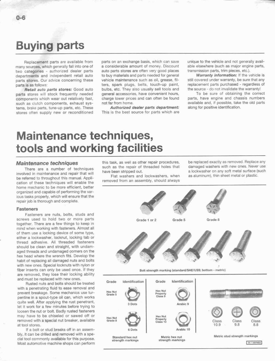
Grade 1 or 2 Grade 5 Grade 8
Grade ldenttfication I Grade Identification
I
with a penetrating flutd to ease removal and
prevent breakage. Some mechanics use tur-
FA",%
pent~ne in a spout-type oil can, which works
$2
quits well. After apply~ng the rust penetrant.
3 Dots
let it work for a few minutes before trying to
loosen the nut or blt. Badly rusted fasteners
may have to be chiseled or sawed off or
+fij
removed with a special nut breaker, available Grede B
at tool stores.
II a bolt or stud breaks off In an assem- 6 aot~
bly, it can be drilled and removed with a spe-
cial tool commonly available for this purpose.
andard hex nut
strength marklngn
Most autornot~ve machine shops can perform
2s Class 9 GI
Anhlc 9
Metfie hex nut
atrength markings
Class Class Class
10.9 9.8 8.8
Metric stud strength markings
Maintenance techniques, tools and working facilities
Fastener sires
For a number of reasons, automobile
manufacturers are making wider and wider
use of metric fasteners. Therefore, it is impor-
tant to be able to tell the difference 'between
standard (sometimes called U.S. or SAE) and
metric hardware, slnce they cannot be Inter-
changed.
kll bolts, whether standard or metric, are
sired accord~ng to diameter, thread pitch and
length. For example. a standard 112 - 13 x 1
bott Is 1/2 inch In diameter, has 13 threads per
inch and is 1 inch long. An MI2 - 1.75 x 25
metric bolt is 12 mm in dtameter, has a thread
pitch of 1.75 mm (the distance between
threads) and is 25 rnm long. Thatwo bolts are
nearly identical, and easily contused, but they
are not interchangeable.
In addition to the differences in diame-
ter, thread p~tch and length, metric and stan-
dard bolts can also be distinguished by
examining the bolt heads. To beg~n with, the
d~stance across the fiats on a standard bolt
head is measured In inches, whlle the same
d~mension on a metric belt 1s wed in millime-
ters [the same is true for nuts). As a result. a
standard wrench should not be used an a
metrtc bolt and a metric wrench should not
be used on a standard bolt. Also, most stan-
dard bolts have slashes radiating out from
the center of the head to denote the grade or
strength of the h l t , which is an indication of
the amount of torque that can be apphed to
It. The greater the number of slashes, the
greater the strength of the bolt. Grades D
through 5 are commonly used on autorno-
biles. Metric bolts have a property class
(grade) number, rather than a slash, molded
into their heads to indtcate bolt strength. In
this case. the higher the number,the stronger
the bolt. Property class numbers 8.8, 9.B and
1O.g are commonly used on automobiles.
Strength markings can also be used to
distinguish standard hex nuts from metric
hex nuts. Many standard nuts have dots
stamped into one side, whlle rnetnc nuts are
mark& with a number. The greater the nurn-
ber of dots. or the higher the number, the
greater the strength of the nut.
Metric studs are also marked on their
ends accordlng to property class (grade).
Larger studs are numbered (the same as
metric bolts), while smaller studs carry a geo-
metric code to denote grade.
It should be noted that many fasteners,
especially Grades 0 through 2, have no dis-
tinguishing marks on them. When such is the
case, the only way to determine whether tl is
standard or metric Is to measure the thread
p~tch or compare it to a known fastener of the
Same size.
Standard fasteners are often referred to
as SAE, as opposed to metric. However, it
should be noted that SAE technically refers to
a non-metric fine thread fastener only.
Coarse thread non-rnetrlc fasteners are
referred to as USS sizes.
Since fasteners of the same size (both
standard and metric) may have different
Metric thread sizes
M-6 ...................................... .. .....................
M-8 ...............................................................
M-10 .............................................................
Pipe thread sizes
U.S. thread sizes
1 /4 - 20 ........................................................
5/16 - 18 ...................................................
511 6 - 24 .......................................................
318 - 16 .........................................................
318 - 24 .........................................................
7/16 - 14 .......................................................
7/76 - 20 .....................................................
1rZ - 13 .........................................................
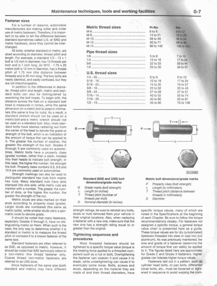
Standard (SAE and USS) bolt
dimens~onslgrade marks
G Grade marks (bolt strength)
L Length (in inches)
T Thread pitch (number of
thm~ds per Inch}
D Nomtnal diameter (in Inches)
Metric bolt dimensionstgrade marks
P Property class (bolt strength)
C Length (in rni//rmete~)
T Mad pitch (distance between
threads in miilimefers)
D Diameter
strength ratings, be sure to relnstalt any bolts,
studs or nuts removed from your vehicle in
their original locations. Also, when replacing
a fastener with a new one, make sure that the
new one has a strength rating equal to or
greater than the original.
Tightening sequences and
procedures
Most threaded fasteners should be
tightened to a specific torque value (torque is
the hvistrng force applied to a threaded com-
ponent such as a nut or bolt). Overtightening
the fastener can weaken it and cause it to
break, while undertightening can cause it to
eventually come loose. Bolts, screws and
studs, depending on the material they are
made of and their thread diameters, have
specific torque values, many of which are
noted In the Specifications at the beglnnlng
of each Chapter. Be sure to folilow the torque
recommendations closely. For fasteners not
assrgned a specrfic torque, a general torque
value chart is presented here as a guide.
These torque values are for dry (unlubricated)
fasteners threaded into steel or cast iron (not
aluminum). As was previously mentioned, the
s~zs and grade of a fastener determine the
amount of torque that can safely be applred
to rt. The figures listed here are approximate
for Grade 2 and Grade 3 fasteners. Higher
grades can tolerate higher torque values.
Fasteners laid out in a pattern, such as
cylinder head bolts, oil pan bolts. differentla1
cover bolts, etc.. must be loosend or tight-
ened in sequence to avoid warping the com-
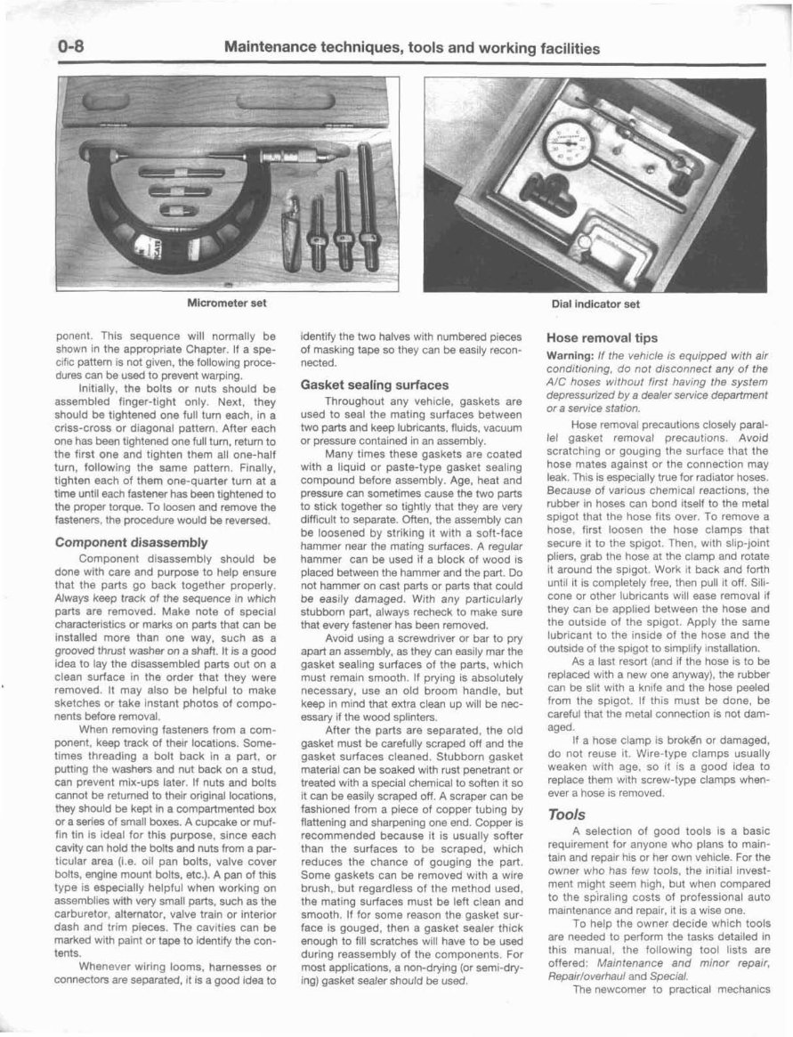
0-8 Maintenance techniques, tools and working facilities
Micrometer set Dial indicator set
ponent. This sequence will normally be
shown In the appropriate Chapter. If a spe-
crflc pattern is not given, the following proce-
dures can be used to prevent warplng.
Initially, the bolts or nuts should be
assembled finger-tlght only. Next, they
should be trghtened one full turn each, in a
crlss-cross or d~agonal pattern. After each
one has been tightened one full turn, return to
the first one and tighten them all one-half
turn, following the same pattern. Finally,
tighten each of them one-quarter turn at a
time unt~l each fastener has been tightened to
the proper torque. To loosen and remove the
fasteners, the procedure would be reversed.
Component disassembly
Component d~sassembly should be
done with care and purpose to help ensure
that the parts go back together properly.
Always keep track of the sequence in which
parts are removed. Make note of special
characteristics or marks on parts that can be
installed more than one way, such as a
grooved thrust washer on a shaft. tt is a good
idea to fay the disassembled parts out on a
clean surface in the order that they were
removed. It may also be helpful to make
sketches or take instant photos of compo-
nents before removal,
When removing fasteners from a com-
ponent, keep track nf therr locations. Some-
times threadlng a bolt back in a part, or
putting the washers and nut back on a stud.
can prevent mlx-ups later. If nuts and bolts
cannot be returned to thelr original locat~ons,
they should be kept in a compartmented box
or a series of small boxes. A cupcake or muf-
fin tln is Ideal for this purpose, slnce each
cavity can hold the bolts and nuts from a par-
ticular area (4.e. oil pan bolts, valve cover
bolts, engine mount bolts, etc.). A pan of this
type rs especially helpful when working on
assemblies with very srnali parts, such as the
carburetor, alternator, valve train or interlor
dash and trim pieces. The cavltles can be
marked with paint or tape to Identify the con-
tents.
Whenever wir~ng looms, harnesses or
connectors are separated, ~t is a good idea to
identify the two halves with numbered pieces
of masking tape so they can be easily recon-
nected.
Gasket sealing surfaces
Throughout any vsh~cle, gaskets are
used to seal the rnat~ng surfaces between
two parts and keep lubricants, flu~ds, vacuum
or pressure contained tn an assembly.
Many t~mes these gaskets are coated
w~th a llquid or paste-type gasket sealing
compound before assembly. Age, heat and
pressure can sometimes cause the two parts
to st~ck together so tightly that they are very
dlfflcult to separate. Often, the assembly can
be loosened by striking it with a soft-face
hammer near the mating surfaces. A regular
hammer can be used if a block of wood IS
placed ktween the hammer and the part. Do
not hammer on cast parts or parts that could
be easily damaged. W~th any particularly
stubborn part, always recheck to make sure
that every fastener has been removed.
Avoid using a screwdriver or bar to pry
apart an assembly, as they can easily mar the
gasket sealing surfaces of the parts, whlch
must remaln smooth. If prying is absolutely
necsssavy, use an old broom handle, but
keep In mlnd that extra clean up will be nec-
essary if the w w d splinters.
After the parts are separated, the old
gasket must be carefully scraped off and the
gasket sulfaces cleaned. Stubborn gasket
material can be soaked with rust penetrant or
treated with a special chemical to soften ~t so
it can be eastly scraped off. A scraper can be
fashioned from a piece of copper tubing by
flattening and sharpening one end. copper is
recommended because it is usuallv softer
than the surfaces to be scraped: which
reduces the chance of gnuglng the part.
Some gaskets can be removed with a wire
brush,. but regardless of the method used,
the matlng surfaces must be left clean and
smooth. If for some reason the gasket sur-
face is gouged, then a gasket sealer thick
enough to fill scratches will have to be used
during reassembly of the components. For
most applicatinns, a non-drying (or semi-dry-
ing) gasket sealer should be used.
Hose removaF tips
Warning: If the veh~cle rs equipped with air
conditioning, do not drsconnect any of the
AIC hoses w~thoui first hanng the system
depressurired by a dealer serwtce department
or a servrce statton.
Hose removal precautt~ns closely paral-
lel gasket removal precautions. Avord
scratching or gouglng the surface that the
hose mates against or the connect~on may
leak. Thls is espec~ally true for radiator hoses.
Because of varlous chemlcal reactions, the
rubber in hoses can bond ~tself to the metal
splgot that the hose fits over. To remove a
hose, first loosen the hose clamps that
secure it to the spigot. Then. with slipjoint
pliers, grab the hose at the clamp and rotate
~taround the spigot. Work ~t back and forth
unt~l rt is completely free, then pull It off. Sill-
cone or other lubr~cants w~ll ease removal if
they can be applied between the hose and
the outside of the spigot. Apply the same
lubr~cant to the inside of the hose and the
outside of the splgol to srrnpllfy lnstallatlon.
As a last resort (and if the hose is to be
replaced with a new one anyway). the rubber
can be slit with a knlfe and the hose peeled
from the spigot. If this must be done, be
careful that the metal connection IS not dam-
aged.
If a hose clamp is brok8n or damaged,
do not reuse ~ t . Wire-type clamps usually
weaken wlth age, so ~t IS a good ldea to
replace them w~th screw-type clamps when-
ever a hose is removed
Tools
A selection of good tools is a basic
requirement for anyone who plans to main-
tain and repalr his or her own vehtcle. For the
owner who has few tools, the inrtjal invest-
ment might seem hrgh, but when compared
to the sr$raling costs of profess~onal auto
maintenance and repair. ~t 1s a wise one.
To help the owner decide which tools
are needed to perform the tasks detailed rn
this manual, the fallowing tool lists are
offered: Maintenance and minor repaw,
Repa!r/overhaul and Specral.
The newcomer to practical rnechan~cs
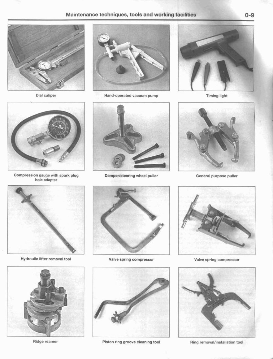
Maintenance techniques, tools and working facilities
Dial caliper
Compression gauge with spark plug
hole adapter
Hand-operated vacuum pump Timtng light
3rlng wheel puller General purpose puller
Hydraulic Imer removal tool Valve sprlng compressor Valve spring cornpressor
Ridge reamer Piston ring groove cleaning took Ring removalfinstallatlon tool
You're Reading a Preview
What's Included?
Fast Download Speeds
Offline Viewing
Access Contents & Bookmarks
Full Search Facility
Print one or all pages of your manual
$39.99
Viewed 14 Times Today


Secure transaction
What's Included?
Fast Download Speeds
Offline Viewing
Access Contents & Bookmarks
Full Search Facility
Print one or all pages of your manual
$39.99
This workshop service repair manual is for the VW Volkswagen Beetle 1300 with a 1.3L 4-cylinder petrol aspirated engine. It includes detailed information on various aspects such as:
- General information
- Automatic transmission
- Body repair
- Brake system
- Chassis electrical
- Clutch system
- Cooling system
- Drivability & troubleshooting
- Emission control
- Engine electrical
- Engine mechanical
- Engine performance and tune-up
- Engine rebuilding
- Exhaust system
- Front disc brake
- Front drum brake
- Front suspension
- Fuel system
- Hydraulic brake
- Lubrication system
- Maintenance
- Manual transmission
- Parking brake
- Precaution
- Rear drum brake rear suspension
- Steering
- Valve system
- Wiring diagram
This comprehensive manual provides detailed exploded views and step-by-step procedures with illustrations and diagrams. It is the same manual used by technicians for vehicle repairs and covers maintenance, servicing, and more. The manual is fully printable, allowing easy access to specific pages or the entire manual.


