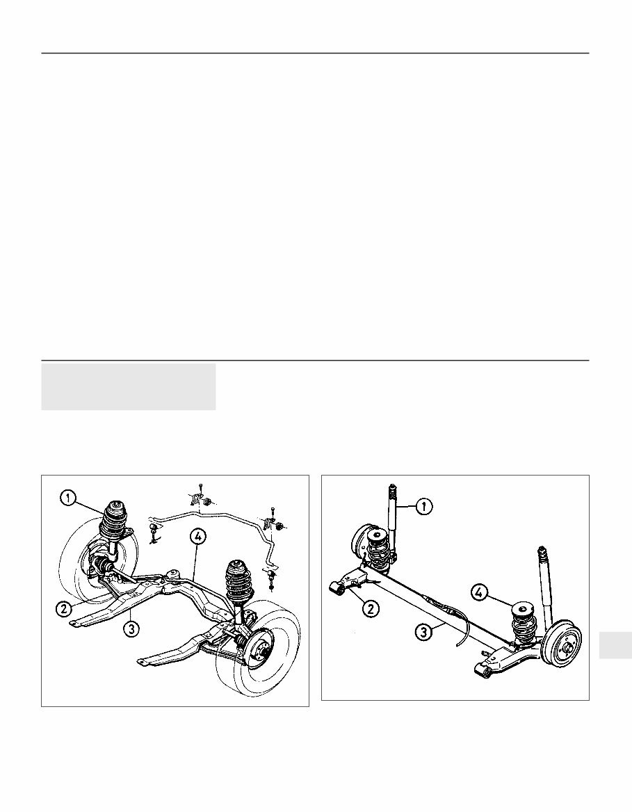
Torque wrench settings (continued) Nm lbf ft Steering Steering gear mounting (to bulkhead) . . . . . . . . . . . . . . . . . . . . . . . . . . 22 16 Steering wheel retaining . . . . . . . . . . . . . . . . . . . . . . . . . . . . . . . . . . . . . 25 18 Tie-rod to steering gear . . . . . . . . . . . . . . . . . . . . . . . . . . . . . . . . . . . . . 95 70 Tie-rod end clamp . . . . . . . . . . . . . . . . . . . . . . . . . . . . . . . . . . . . . . . . . 20 15 Tie-rod end to suspension strut balljoint . . . . . . . . . . . . . . . . . . . . . . . . 60 44 Steering shaft to flexible coupling . . . . . . . . . . . . . . . . . . . . . . . . . . . . . 22 16 Steering gear pinion to flexible coupling . . . . . . . . . . . . . . . . . . . . . . . . 22 16 Steering gear pinion . . . . . . . . . . . . . . . . . . . . . . . . . . . . . . . . . . . . . . . . 40 30 Steering gear damper adjuster . . . . . . . . . . . . . . . . . . . . . . . . . . . . . . . . 60 44 Fluid pipe to power steering gear unions . . . . . . . . . . . . . . . . . . . . . . . . 42 31 Fluid pipe to power steering pump union . . . . . . . . . . . . . . . . . . . . . . . . 28 21 Fluid pipe to pipe and pipe to hose unions . . . . . . . . . . . . . . . . . . . . . . 28 21 Power steering pump mounting: 1.6 litre models (up to 1992) . . . . . . . . . . . . . . . . . . . . . . . . . . . . . . . . 30 23 1.8 and 2.0 litre models (up to 1992): Bolts “A” and “C” (refer to text) . . . . . . . . . . . . . . . . . . . . . . . . . . . 25 18 Bolts “B” (refer to text) . . . . . . . . . . . . . . . . . . . . . . . . . . . . . . . . . . 40 30 SOHC models (from 1993) . . . . . . . . . . . . . . . . . . . . . . . . . . . . . . . . . 20 15 DOHC models (from 1993): Bolts “1” and “2” (refer to text) . . . . . . . . . . . . . . . . . . . . . . . . . . . 25 18 Bolts “3” and “4” (refer to text) . . . . . . . . . . . . . . . . . . . . . . . . . . . . 18 13 Power steering pump pulley (1.6 litre models) . . . . . . . . . . . . . . . . . . . . 25 18 Steering column to dashboard mounting bracket . . . . . . . . . . . . . . . . . 22 16 Steering column upper right hand mounting . . . . . . . . . . . . . . . . . . . . . 22 16 Roadwheels Roadwheel . . . . . . . . . . . . . . . . . . . . . . . . . . . . . . . . . . . . . . . . . . . . . . . 110 81 1 General description 1 The front suspension consists of MacPherson struts, lower arms, and an anti-roll bar. The lower arms and the anti-roll bar are mounted on a detachable U-shaped front subframe, which also carried the rear engine/ transmission mounting (see illustration). 2 Each lower arm is attached to the subframe by a horizontal front bush and a vertical rear bush. In conjunction with the steering geometry, this arrangement allows the front wheels to steer themselves against any imbalance in the braking forces. This would maintain stability when braking with one side of the vehicle on a slippery surface, and the other on dry tarmac. 3 The hub carriers are mounted between the lower ends of the MacPherson struts, and the lower arms, and carry the double row ball type wheel bearings and the brake assemblies. 4 The rear suspension on SOHC models is of semi-independent type, consisting of a torsion beam and trailing arms with double-conical coil springs and telescopic shock absorbers. The front ends of the trailing arms are attached to the vehicle underbody by horizontal bushes, and the rear ends are located by the shock absorbers, which are bolted to the underbody at their upper ends. Suspension and steering 10•3 1.1 Front suspension layout - all models 1.4 Rear suspension layout - SOHC model (model with rear drum brakes shown) 1 Shock absorber 2 Trailing arm 3 Torsion beam 4 Coil spring 1 MacPherson strut 2 Lower arm 3 Subframe 4 Anti-roll bar 10
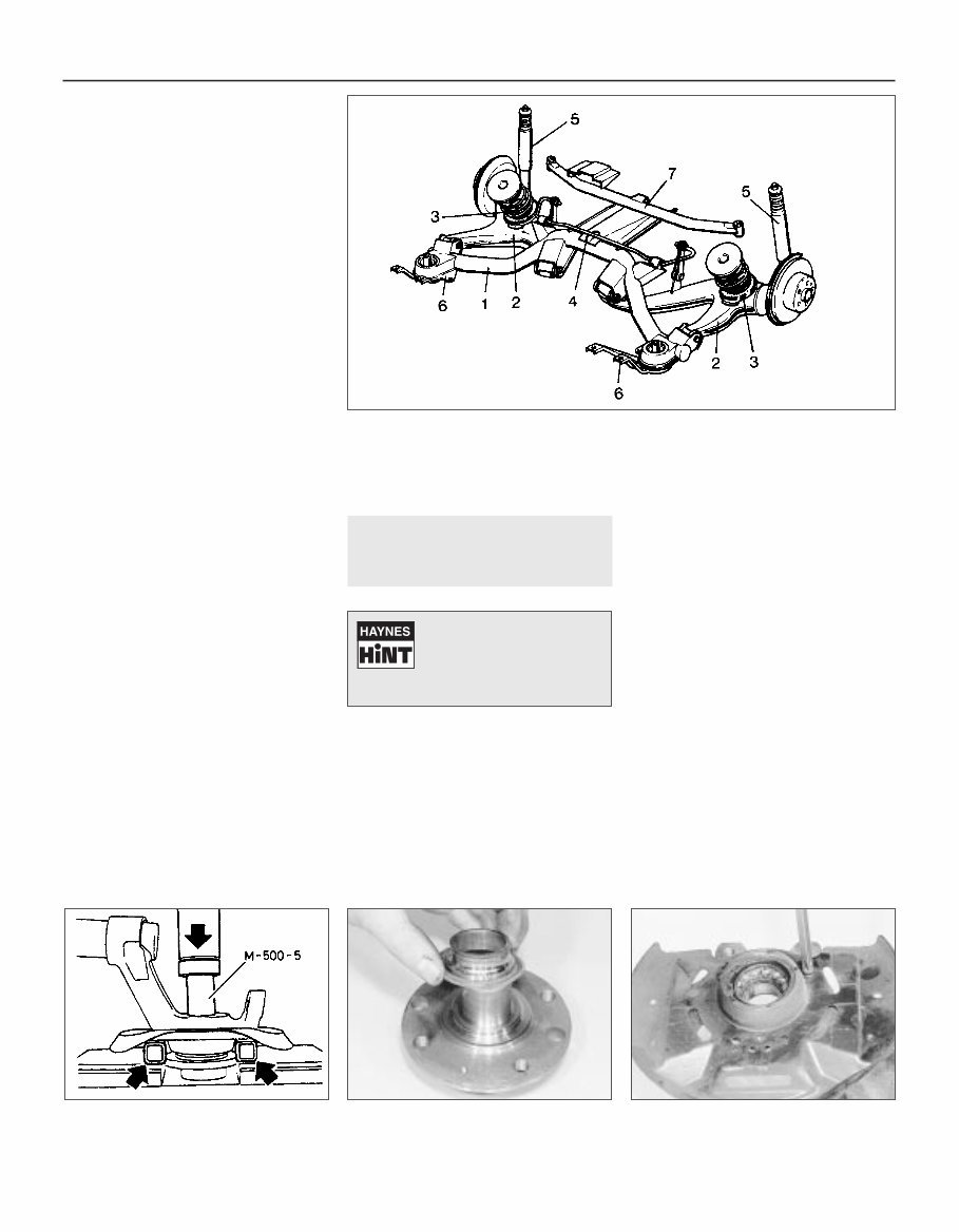
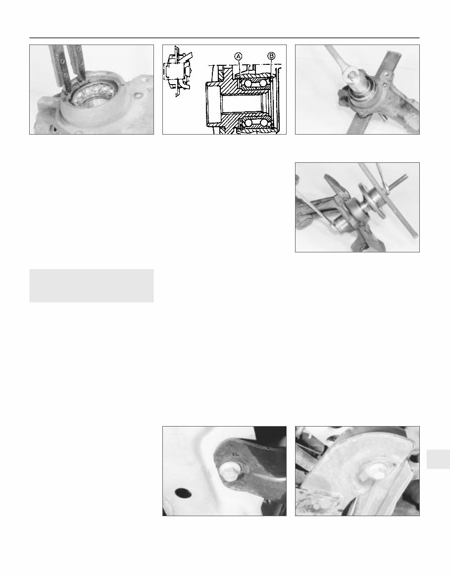
The coil springs are mounted independently of the shock absorbers, and act directly between the trailing arms and the underbody. Certain models are fitted with an anti-roll bar, which is mounted between the torsion beam and the rear ends of the trailing arms (see illustration). 5 A manual rear suspension level control system is available as standard equipment on some models, and as an optional extra on others. The system operates using compressed air filled shock absorbers. The rear suspension level is adjusted by altering the air pressure in the shock absorbers, through a valve located in the luggage compartment. 6 The rear suspension on DOHC models is of fully independent type, consisting of semi-trailing arms, with double-conical coil springs, telescopic shock absorbers and an anti-roll bar. The front end of each semi-trailing arm is attached to a suspension crossmember by two horizontal bushes, and the rear ends are located by the shock absorbers, which are bolted to the underbody at their upper ends. The coil springs are mounted independently of the shock absorbers, and act directly between the semi-trailing arms and the underbody. The anti-roll bar is located on the suspension crossmember, and is attached to each semi-trailing arm by a vertical link. The suspension crossmember is bolted directly to the vehicle underbody at its forward end (see illustration). 7 The steering gear is of rack-and-pinion type. Movement is transmitted to the front wheels through tie-rods, which are connected to the rack through a sliding sleeve at their inner ends, and to the suspension struts through balljoints at their outer ends. 8 The steering column consists of an outer column that incorporates a collapsible section, and a shaft connected to a flexible coupling at its lower end. 9 Power steering is fitted as standard to certain models and is available as an option on others. The power steering is hydraulically operated, and pressure is supplied by a fluid pump driven by way of a drivebelt from the engine crankshaft. On 1.8 and 2.0 Litre models, fluid cooler pipes are mounted beneath the radiator to keep the temperature of the hydraulic fluid within operating limits. 2 Front wheel bearing - renewal 4 Removal 1 Remove the relevant suspension strut/hub carrier assembly, as described in Section 4. 2 Unscrew the securing screw, and remove the brake disc from the hub. 3 Support the hub carrier on two metal bars positioned as shown (see illustration), then using a metal bar or tube of similar diameter, press or drive the hub from the wheel bearing. Alternatively, screw two roadwheel bolts into the hub and, using progressively thicker packing pieces, tighten the bolts to force the hub from the bearing. Note that one half of the inner bearing race will remain on the hub. 4 Using a puller, pull the half inner bearing race from the hub. Alternatively, support the bearing race on suitably thin metal bars, and press or drive the hub from the bearing race (see illustration). 5 Remove the three securing screws, and lift the brake disc shield from the hub carrier (see illustration). 6 Extract the inner and outer bearing retaining circlips (see illustration). 7 Using a puller, pull the bearing from the hub carrier, applying pressure to the outer race. Alternatively, support the hub carrier, and press or drive out the bearing. Refitting 8 Before installing the new bearing, thoroughly clean the bearing location in the hub carrier, and fit the outer bearing retaining circlip, “A” (see illustration). Note that the circlip tabs should be positioned towards the bottom of the hub carrier. 10•4 Suspension and steering 1.6 Rear suspension layout - DOHC model 1 Crossmember 2 Semi-trailing arm 3 Coil springs 4 Anti-roll bar 5 Shock absorber 6 Crossmember mounting bracing bracket 7 Crossmember rear tube 2.5 Removing a brake disc shield securing screw 2.4 Removing the half inner bearing race from the hub 2.3 Pressing the front hub from the wheel bearing The bearing will probably be destroyed during the removal operation. The use of a puller will greatly ease the procedure
9 Press or drive the new bearing into position until it contacts the outer circlip, applying pressure to the outer race (see illustration). 10 Fit the inner bearing retaining circlip, with the tabs positioned towards the bottom of the hub carrier. 11 Fit the brake disc shield. 12 Press or draw the hub into the bearing. The bearing inner track must be supported during this operation. This can be achieved using a socket, long bolt, washers and a length of bar as shown (see illustration). 13 Refit the brake disc. 14 Refit the suspension strut/hub carrier assembly, as described in Section 4. 3 Front subframe - removal and refitting 4 Note: Suitable equipment will be required to support the engine during this procedure. A balljoint separator tool will be required. The lower arm to suspension strut balljoint nut locking pins must be renewed on refitting Removal 1 The subframe is removed complete with the lower arms and the anti-roll bar as an assembly. 2 Before removing the subframe, the engine must be supported from its left hand lifting bracket. Ideally, the engine should be supported using a strong wooden or metal beam resting on blocks positioned securely in the channels at the sides of the engine compartment. The Vauxhall special tool designed specifically for this purpose is shown in Chapter 7A. Alternatively, the engine can be supported using a hoist and lifting tackle. However in this case, the hoist must be of such a design as to enable the engine to be supported with the vehicle raised off the ground, leaving sufficient clearance to withdraw the subframe from under the front of the vehicle. 3 Where applicable, remove the wheel trims, then loosen the front roadwheel bolts on both sides of the vehicle. Apply the handbrake, then jack up the front of the vehicle, and support securely on axle stands (see “Jacking and Vehicle Support”) positioned under the body side members. Remove the front roadwheels. 4 Remove the front section of the exhaust system, with reference to Chapter 4C. On DOHC models, unbolt the oil cooler hose bracket from the right hand side of the subframe. 5 Working on one side of the vehicle, extract the locking pin, then unscrew the castellated nut from the lower arm to suspension strut balljoint. 6 Using a balljoint separator tool, disconnect the lower arm to suspension strut balljoint. 7 Repeat paragraphs 5 and 6 for remaining lower arm. 8 Ensure that the engine is adequately supported, then unscrew and remove the two nuts and washers securing the rear engine/transmission mounting to the subframe. 9 Support the subframe on a trolley jack, with an interposed wooden beam to prevent the subframe from tipping as it is withdrawn. 10 Unscrew and remove the six bolts securing the subframe to the vehicle underbody. Note that the rear bolts also secure the lower arms to the subframe (see illustrations). The bolts are very tight, and an extension bar will probably be required to loosen them. 11 Lower the jack supporting the subframe, and withdraw the assembly from under the front of the vehicle. 12 If desired, the anti-roll bar and/or the lower arms can be removed from the subframe, with reference to Sections 8 and 5 respectively. Refitting 13 Refitting is a reversal of removal, remembering the following points. 14 If the anti-roll bar and/or the lower arms have been removed from the subframe, refit them with reference to Section 8 and/or 5, as applicable. 15 Tighten all nuts and bolts to the specified torques, noting that the rear subframe to underbody bolts must be tightened in stages see Specifications. 16 Secure the lower arm to suspension strut balljoint nuts with new locking pins. 17 Refit the front section of the exhaust system, with reference to Chapter 4C. On DOHC models, refit the oil cooler hose bracket to the right hand side of the subframe. 18 Finally tighten the roadwheel bolts when the vehicle has been lowered to the ground, and where applicable, refit the wheel trims. Suspension and steering 10•5 2.9 Fitting a new front wheel bearing using a socket, nut, bolt, washers, and length of bar 3.10B Front subframe rear securing bolt which also secures rear end of lower arm 3.10A Front subframe front securing bolt 2.12 Drawing the hub into the bearing using improvised tools 2.8 Cross sectional view of front wheel bearing/hub assembly A Outer bearing retaining circlip B Inner bearing retaining circlip 2.6 Extracting the outer bearing retaining circlip 10
You're Reading a Preview
What's Included?
Lifetime Access
Fast Download Speeds
Offline Viewing
Access Contents & Bookmarks
Full Search Facility
Print one or all pages of your manual
$35.99
1988-1995 VAUXHALL CAVALIER Service Repair Manual instant access
This Service Repair Manual is an essential resource for anyone working on the 1988-1995 Vauxhall Cavalier. It contains comprehensive details, technical data, and a complete list of parts with diagrams and pictures. Whether you are a professional mechanic or a DIY enthusiast, this manual covers a wide range of services including:
Complete Engine Service
Fuel System Service
Factory Repair Procedures
Wiring Diagrams
Gearbox
Exhaust System
Suspension
Fault Finding
Clutch Removal and Installation
Front Suspension
Bodywork
Gearbox Service, Removal and Installation
Cooling System
Detailed Specifications
Transmission
Factory Maintenance Schedules
Electrics
Engine Firing Order
Brake Servicing Procedures
Driveshaft
Timing Chain Service
Exhaust Service
Abundant Illustrations
Lots of Pictures & Diagrams
Plus Lots More
This manual is compatible with all versions of Windows & Mac and is available in English. It is printable, making it convenient to take into the garage or workshop. With step-by-step instructions, it is designed to be easy to follow for any skill level. Whether you are looking to save money by doing your own repairs or seeking detailed guidance, customer satisfaction is always guaranteed with this Service Repair Manual.
Reviews
Q&A
Recently Viewed
5,521,897Happy Clients
2,594,462eManuals
1,120,453Trusted Sellers
15Years in Business
Price:
Actual Price:
1988-1995 VAUXHALL CAVALIER Service Repair Manual instant access