2014 Vauxhall Agila, 1.2VVT, Petrol Service & Repair Manual
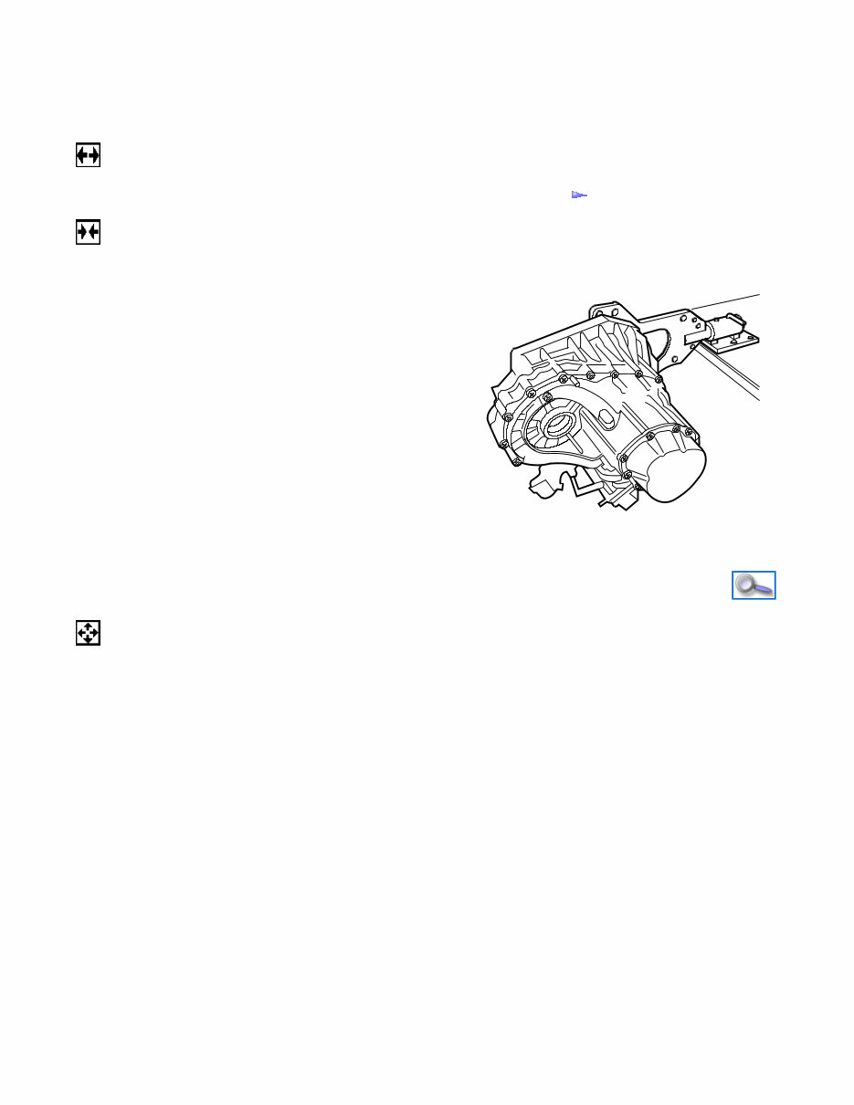
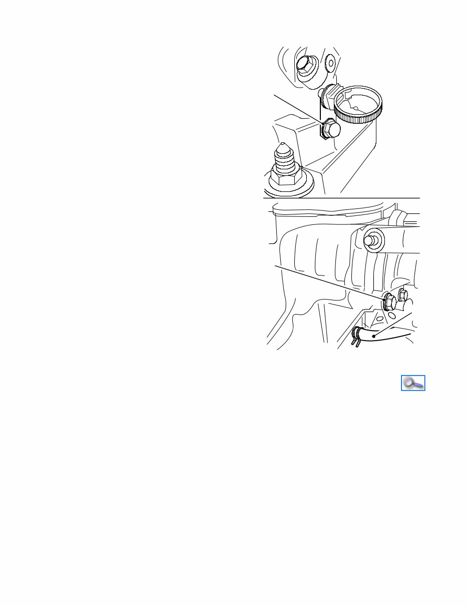
1st or 2nd Gear and Output Shaft Overhaul Remove Install Disassemble 1. Remove transmission from vehicle – see operation “Manual Transmission Remove and Install” 2. Attach transmission to transmission support • Install transmission support bracket to transmission • Install Clutch Housing Holder KM-6115 – Install 2x bolt, nut 3. Install transmission to bench mounted support bracket • Install Clutch Housing Holder KM-6115 to KM-113-2 Note: 2x technician are required. S 0017541 4. Remove transmission upper wiring harness bracket from transmission • Remove bolt (1) 5. Remove breather hose (2) from transmission assembly • Release from support clip • Release clip, then pull off 6. Remove breather support bracket from transmission assembly • Remove bolt (3) 7. Remove reverse lamp switch from transmission Page 1 of 19 6/11/2016 http://localhost:9080/tis2web/?target=A20073NK&target.method=getPage
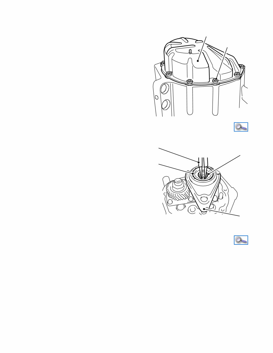
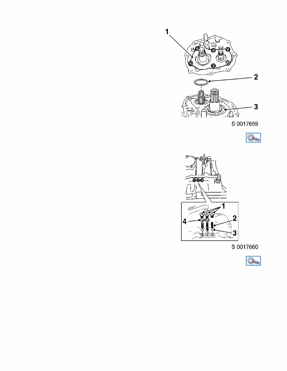
S 0017738 2 3 1 8. Remove rear cover (2) from transmission assembly • Remove 8x bolt (1) • Separate cover from transmission – Use Seal Breaker KM-J-37228 Note: Do not distort rear cover when removing from transmission. Page 2 of 19 6/11/2016 http://localhost:9080/tis2web/?target=A20073NK&target.method=getPage
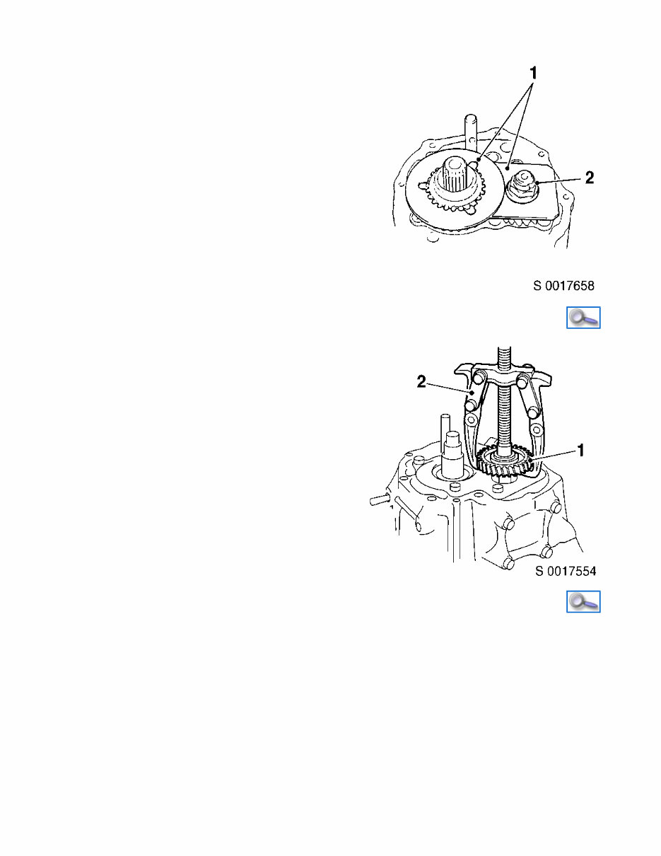
S 0017548 1 2 9. Remove circlip (3) and hub plate (1) from 5th gear shaft • Using Circlip Pliers KM-443-B (2) 10. Remove roll pin (4) from 5th gear shift fork 11. Remove 5th gear, shift fork, synchronizer sleeve, hub assembly with synchronizer ring • Using Bearing Puller KM-161-B 1 2 3 4 S 0017657 12. Remove nut (2) from output shaft • Install 5th gear to input shaft • Install Gear Holder DT-49283 (1) • Unfasten caulking and then remove nut • Remove Gear Holder DT-49283 and 5th gear with bearing Page 3 of 19 6/11/2016 http://localhost:9080/tis2web/?target=A20073NK&target.method=getPage
13. Remove 5th gear (1) from output shaft • Using Bearing Puller KM-161-B (2) 14. Remove case plate (1) from rear transmission assembly • Remove 5x bolt, screw 15. Remove bearing set shim (2) from output shaft 16. Remove snap ring (3) from 5th gear shaft Page 4 of 19 6/11/2016 http://localhost:9080/tis2web/?target=A20073NK&target.method=getPage
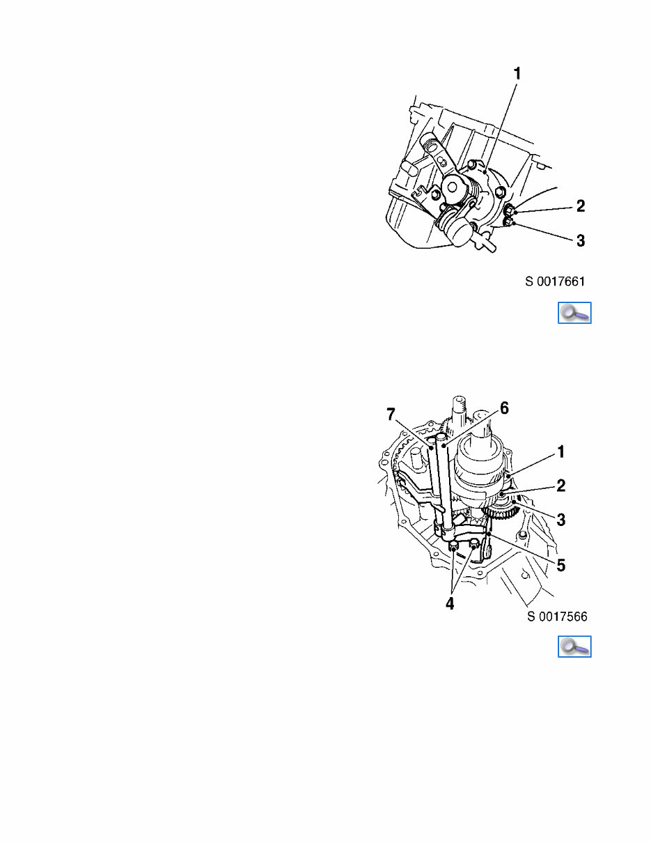
17. Remove 3x gear shift locator • Remove 3x bolt (1), 2x washer (4), 3x spring (2), 3x steel ball (3) 18. Remove reverse interlock guide bolt (3) with washer and gear shift interlock bolt (2) with washer from transmission housing 19. Remove gear shift and selector assembly (1) from transmission assembly 20. Remove 4x bolt, gasket Page 5 of 19 6/11/2016 http://localhost:9080/tis2web/?target=A20073NK&target.method=getPage
21. Release rear transmission case from front transmission case • Remove 13x bolt 22. Remove rear transmission case from front transmission case • Separate using Seal Breaker KM-J-37228 23. Remove reverse gear shift lever (5) from front transmission case • Remove 2x bolt (4) 24. Remove reverse gear shaft (1), washer (2) and idler gear (3) from front transmission case • Pull out gear shaft and washer, then remove idler gear 25. Remove 5th gear guide (6) and shift shaft (7) from front transmission case • Pull out 26. Remove all gear and shaft assemblies from front transmission case • Release input shaft from front transmission case – Tap with plastic hammer, then remove all assemblies 27. Remove output shaft side bearing outer race from rear transmission case • Using suitable tool 28. Remove output shaft side bearing outer race from front transmission case • Using Remover J-26941 , Adapter KM-483 and Slide Hammer KM- 313 Page 6 of 19 6/11/2016 http://localhost:9080/tis2web/?target=A20073NK&target.method=getPage
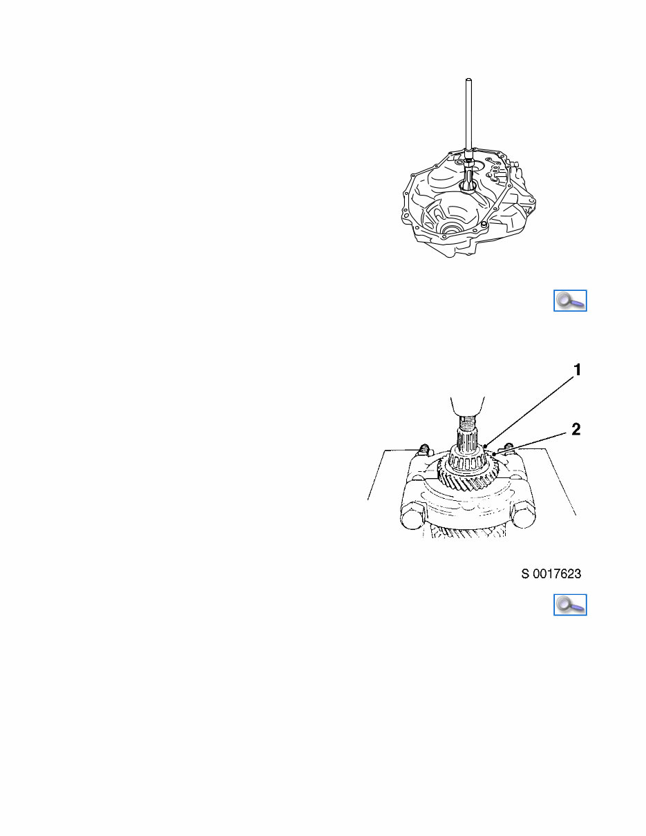
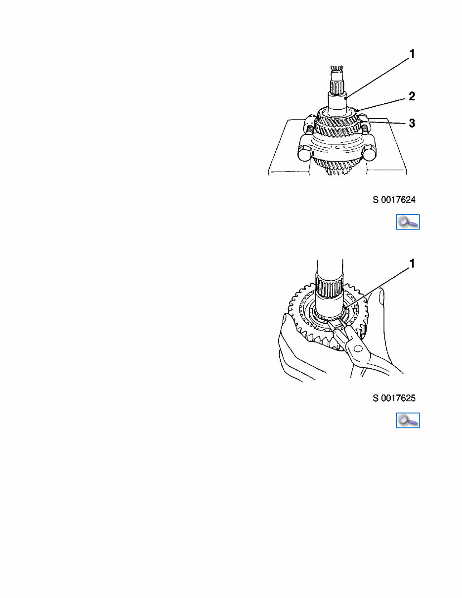
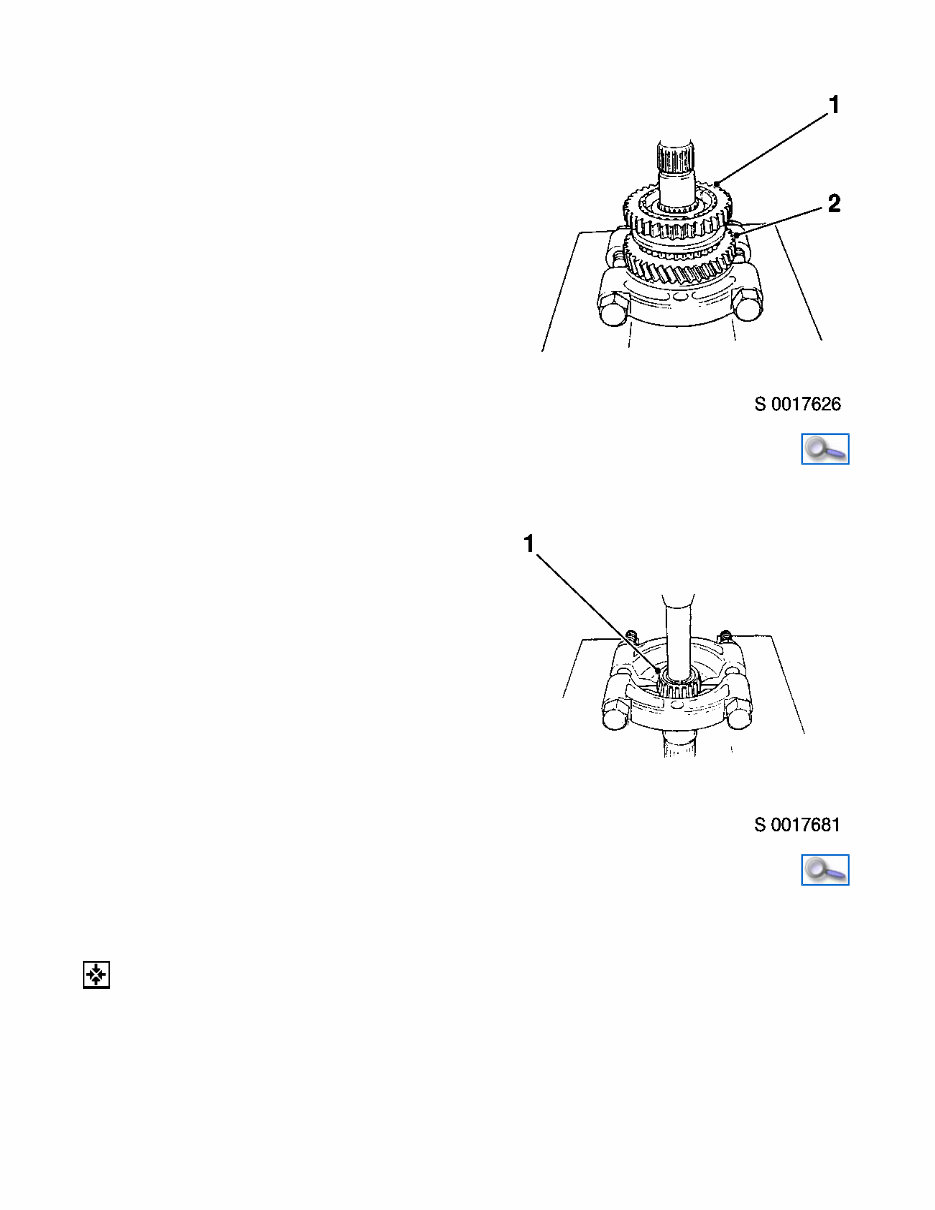
S 0017668 29. Remove selector and output shaft fork from output synchronizer bearing • Lift off Important: To avoid damage to gear teeth, use flat side of the puller. 30. Remove outer bearing (1) and 4th gear (2) from output shaft • Using commercially available bearing puller and hydraulic press 31. Remove 4th gear spacer (1), 3rd (2) and 2nd gear (3) from output shaft Important: To avoid damage to gear teeth, use flat side of the puller. • Using commercially available bearing puller and hydraulic press Page 7 of 19 6/11/2016 http://localhost:9080/tis2web/?target=A20073NK&target.method=getPage
32. Remove 2nd synchronizer outer ring, centre cone and inner ring • Lift off 33. Remove snap ring (1) from low speed synchronizer hub assembly output shaft • Using suitable tool Important: To avoid damage to gear teeth, use flat side of the puller. 34. Remove low speed synchronizer sleeve and hub assembly (1) with 1st gear (2) • Using commercially available bearing puller and hydraulic press Page 8 of 19 6/11/2016 http://localhost:9080/tis2web/?target=A20073NK&target.method=getPage
Assemble 35. Remove 1st gear needle bearing from output shaft 36. Remove outer bearing (1) from output shaft 37. Clean all components and inspect for abnormality 38. Replace any components, if necessary 39. Assemble synchronizer sleeve and hub assembly • Install hub, sleeve, 3x key and 2x spring 40. Ensure output shaft oil hole is free from any obstruction 41. Install side bearing (1) to output shaft, right side • Using Installer KM-781 and hydraulic press Page 9 of 19 6/11/2016 http://localhost:9080/tis2web/?target=A20073NK&target.method=getPage
Fixing problems in your vehicle is made easier with the 2014 Vauxhall Agila B Service & Repair Manual. Whether you are a professional mechanic or a DIY enthusiast, this manual contains comprehensive instructions and procedures to help you fix your vehicle correctly the first time, with customer support available via email.
The durability of your vehicle is unquestionable, but constant use can lead to deterioration and a need to replace certain parts. This manual empowers you to save money with do-it-yourself repairs, as many components are simple to mount without requiring professional help.
This manual includes:
Comprehensive technical data and detailed diagrams
A complete list of car parts and accessories
Step-by-step instructions and easy-to-follow illustrations
Wiring schematics and specifications for accurate repairs
Covering all models and repairs from A-Z, it offers vehicle-specific information used by dealership technicians to maintain, service, diagnose, and repair your car. The format is user-friendly, allowing you to print only the necessary pages and diagrams as needed.
For a sample of the manual’s quality, a couple of basic screen shots are included. Please note that these screen shots may be from a different model but serve as a demonstration of the manual's clarity and quality.