BRAKE – BRAKE SYSTEM BR–1 BR BRAKE SYSTEM PRECAUTION 1. Necessary care must be taken to replace each part properly as it could affect the brake system performance. This could cause driving hazards. Replace each part with an identical part with the same number. 2. It is very important to keep parts and the area clean when repairing the brake system. 3. If the vehicle is equipped with a mobile communication system, refer to the precautions in the INTRODUCTION section.
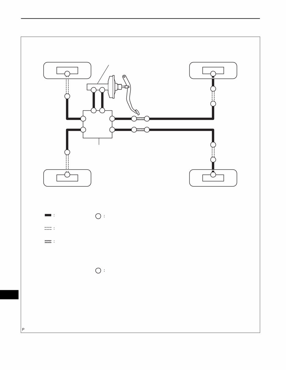
BR–2 BRAKE – BRAKE SYSTEM BR SYSTEM DIAGRAM A A A A A A A A A A A A A A A A B B Brake Tube Flexible Hose A B Union Bolt Torque: 30 N*m (310 kgf*cm, 22 ft*lbf) w/ ABS: Brake Tube Way BRAKE MASTER CYLINDER BRAKE ACTUATOR for use without SST: Union Nut Torque: 15 N*m (155 kgf*cm, 11 ft*lbf) for use with SST: Union Nut Torque: 14 N*m (143 kgf*cm, 10 ft*lbf) A A A A C130323E03
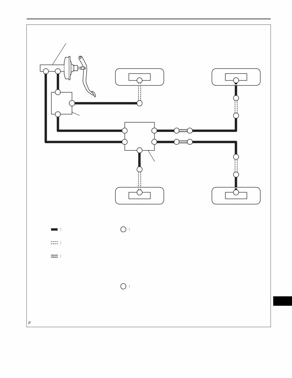
BRAKE – BRAKE SYSTEM BR–3 BR w/o ABS: BRAKE MASTER CYLINDER BRAKE TUBE WAY PROPORTIONING VALVE Brake Tube Flexible Hose Brake Tube Way for use without SST: Union Nut Torque: 15 N*m (155 kgf*cm, 11 ft*lbf) for use with SST: Union Nut Torque: 14 N*m (143 kgf*cm, 10 ft*lbf) Union Bolt Torque: 30 N*m (310 kgf*cm, 22 ft*lbf) A B B A A A A A A A A A A A A A A A A A A A A A A B C133161E01
BR–4 BRAKE – BRAKE SYSTEM BR PROBLEM SYMPTOMS TABLE HINT: Use the table below to help you find the cause of the problem. The numbers indicate the ranked order of probability of each of the possible causes. Check each part in the order suggested. If necessary, replace the applicable parts. Symptom Suspected area See page Low pedal or spongy pedal 1. Fluid leakage in brake system - 2. Air in brake system BR-10 3. Piston seal (Worn or damaged) BR-50 4. Wheel cylinder cup (Damaged) BR-62 5. Brake master cylinder (Faulty) BR-29 Brake drag 1. Brake pedal free play (Minimum) BR-8 2. Parking brake lever travel (Out of adjustment) PB-2 3. Rear drum brake shoe clearance (Out of adjustment) BR-67 4. Pad (Cracked or distorted) BR-51 5. Brake shoe (Cracked or distorted) BR-62 6. Front disc brake piston (Stuck) BR-50 7. Piston (Stuck) BR-62 8. Front disc brake piston (Frozen) BR-50 9. Piston (Frozen) BR-62 10. Tension or return spring (Faulty) BR-60 11. Booster system (Vacuum leakage) BR-5 12. Brake master cylinder (Faulty) BR-29 Brake pull 1. Front disc brake piston (Stuck) BR-50 2. Piston (Stuck) BR-62 3. Pad (Oily) BR-51 4. Brake shoe (Oily) BR-62 5. Front disc brake piston (Frozen) BR-50 6. Piston (Frozen) BR-62 7. Front disc (Scored) BR-51 8. Rear brake drum (Scored) BR-62 9. Pad (Cracked or distorted) BR-51 10. Brake shoe (Cracked or distorted) BR-62 Hard pedal but braking inefficient 1. Fluid leakage in brake system - 2. Air in brake system BR-10 3. Front disc brake piston (Stuck) BR-50 4. Piston (Stuck) BR-62 5. Pad (Cracked or distorted) BR-51 6. Brake shoe (Cracked or distorted) BR-62 7. Pad (Oily) BR-51 8. Brake shoe (Oily) BR-62 9. Pad (Glazed) BR-51 10. Brake shoe (Glazed) BR-62 11. Front disc (Scored) BR-51 12. Rear brake drum (Scored) BR-62 13. Booster system (Vacuum leakage) BR-5
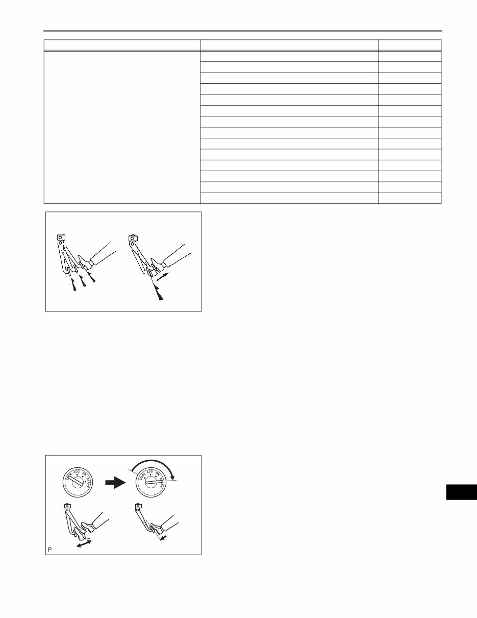
BRAKE – BRAKE SYSTEM BR–5 BR ON-VEHICLE INSPECTION 1. INSPECT BRAKE BOOSTER (a) Check the air tightness. (1) Start the engine and stop it after 1 or 2 minutes. Depress the brake pedal several times slowly. HINT: • If the pedal can be depressed to the floor on the 1st time, but cannot be depressed as far on the 2nd or 3rd times, the booster is airtight. If not, inspect the vacuum check valve. • If the vacuum check valve is normal, replace the brake booster assembly. (2) Depress the brake pedal while the engine is running, and stop the engine with the pedal depressed. HINT: • If there is no change in the pedal reserve distance after holding the pedal for 30 seconds, the booster is airtight. If not, inspect the vacuum check valve. • If the vacuum check valve is normal, replace the brake booster assembly. (b) Check the operation. (1) Depress the brake pedal several times with the engine stopped and check that there is no change in the pedal reserve distance. (2) Depress the brake pedal and start the engine. HINT: • If the pedal goes down slightly, the operation is normal. If not, inspect the vacuum check valve. • If the vacuum check valve is normal, replace the brake booster assembly. Noise from brakes 1. Pad (Cracked or distorted) BR-51 2. Brake shoe (Cracked or distorted) BR-62 3. Installation bolt (Loose) BR-48 4. Front disc (Scored) BR-51 5. Rear brake drum (Scored) BR-62 6. Pad support plate (Loose) BR-51 7. Sliding pin (Worn) BR-48 8. Pad (Dirty) BR-51 9. Brake shoe (Dirty) BR-62 10. Pad (Glazed) BR-51 11. Brake shoe (Glazed) BR-62 12. Tension or return spring (Faulty) BR-60 13. Anti-squeal shim (Damaged) BR-48 14. Shoe hold down spring (Damaged) BR-60 Symptom Suspected area See page NO GOOD GOOD 3rd 2nd 1st BR02238E02 C121844
You're Reading a Preview
What's Included?
Lifetime Access
Fast Download Speeds
Offline Viewing
Access Contents & Bookmarks
Full Search Facility
Print one or all pages of your manual
$36.99
2008 Toyota Yaris Service & Repair Manual Software
The 2008 Toyota Yaris Service & Repair Manual is a comprehensive guide designed to assist in maintaining and repairing your vehicle. It provides detailed instructions, diagrams, and step-by-step procedures to troubleshoot and fix any issues with the 2008 Toyota Yaris. Whether you are a professional mechanic or a DIY enthusiast, this manual is a valuable resource for servicing and repairing your Toyota Yaris.
This manual covers various models of the 2008 Toyota Yaris, including:
2008 Toyota Yaris Hatchback
2008 Toyota Yaris Sedan
2008 Toyota Yaris RS
2008 Toyota Yaris S
Each model is extensively covered, providing the necessary information for repairs or maintenance tasks such as oil changes, brake pad replacements, or troubleshooting electrical issues. The 2008 Toyota Yaris Service & Repair Manual is a valuable resource for addressing unexpected car troubles and maintaining your Toyota Yaris with confidence.
Reviews
Q&A
Recently Viewed
5,521,897Happy Clients
2,594,462eManuals
1,120,453Trusted Sellers
15Years in Business
Price:
Actual Price:
2008 Toyota Yaris Service & Repair Manual Software