FOREWORD This repair manual has been prepared to provide essential in- formation on body panel repair methods (including cutting and welding operations, but excluding painting) for the TOYOTA VENZA. Applicable models: AGV 10, 15 series GGV 10, 15 series This manual consists of body repair methods, exploded dia- grams and illustrations of the body components and other in- formation relating to body panel replacement such as handling precautions, etc. However, it should be noted that the front fend- ers of this TOYOTA model are bolted on and require no welding. When repairing, do not cut and join areas that are not shown in this manual. Only work on the specified contents to maintain body strength. Body construction will sometimes differ depending on specifica- tions and country of destination. Therefore, please keep in mind that the information contained herein is based on vehicles for general destinations. For the repair procedures and specifications other than collision- damaged body components of the TOYOTA VENZA refer to the repair manuals. If you require the above manuals, please contact your TOYOTA dealer. All information contained in this manual is the most up-to-date at the time of publication. However, specifications and procedures are subject to change without prior notice.
ABOUT THIS MANUAL Scope of the repair work explanation S This text explains the welding panel replacement instructions from the vehicle’s white body condi- tion. We have abbreviated the explanations of the removal and reinstallation of the equipment parts up to the white body condition and of the installation, inspection, adjustment and final inspection of equipment parts after replacing the weld panel. Section categories S This manual has been divided as shown below. Section Title Contents Examples INTRODUCTION Explanation of general body repair. Views of welded panel replacement instructions. Cautionary items. Views of weld panel replacement instructions. BODY PANEL REPLACEMENT Instructions for replacing the weld panels from the white body condition, from which bolted parts have been removed, with individual supply parts. Front side member replacement. Quarter panel replacement. BODY DIMENSIONS Body aligning measurements. Dimension diagrams. PAINT S COATING Scope and type of anti-rust treatment, etc. together with weld panel replacement. Under coating. Body sealer. Contents omitted from this manual. S Make sure to perform the following essential procedures, although they are omitted in this manual. (1) Clean and wash removed parts, if necessary. (2) Visual inspection.
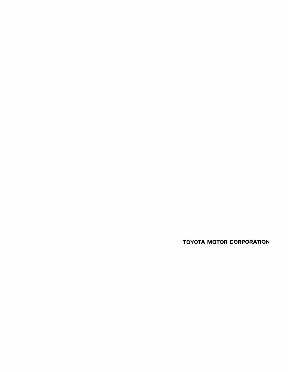
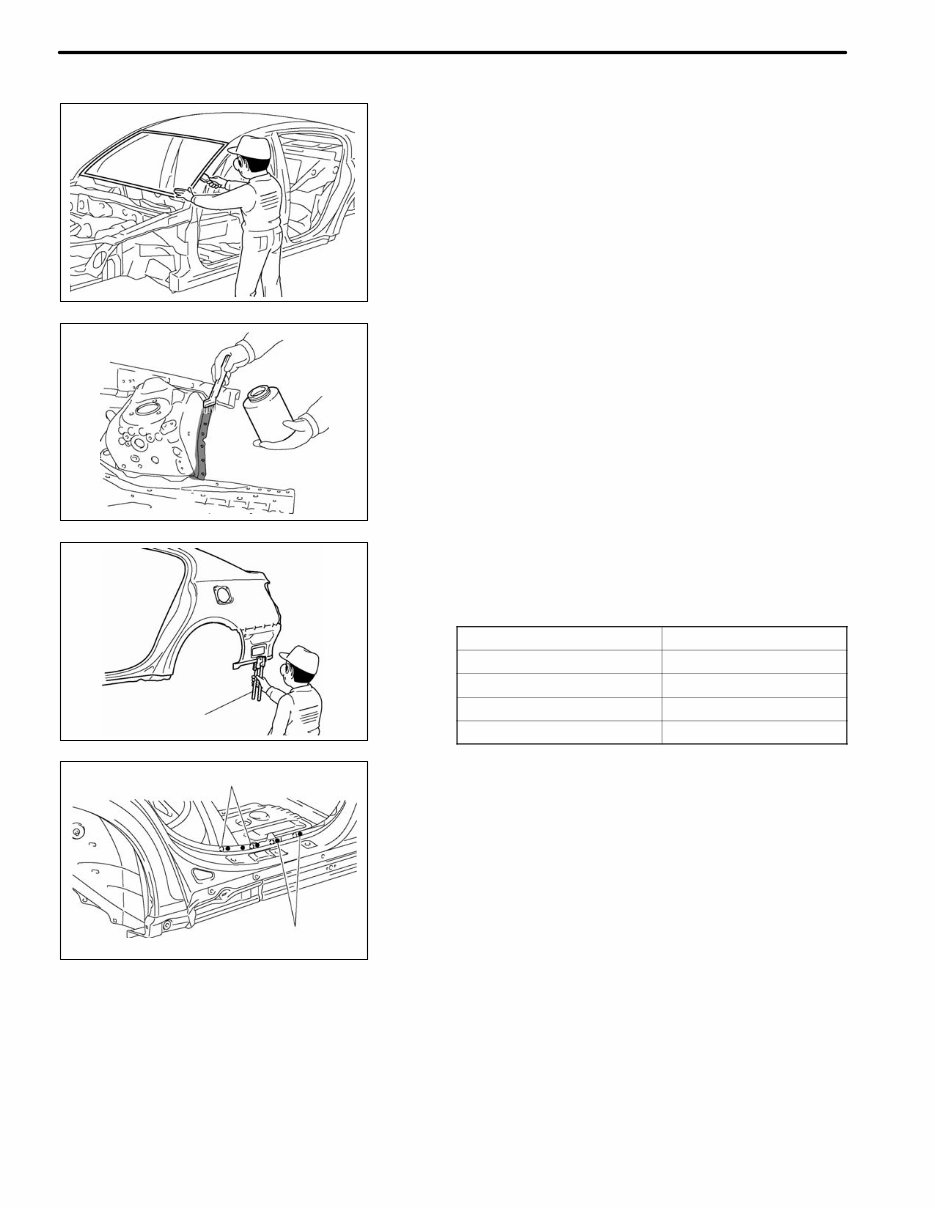
F33003 F33000 F33001 F33002 Glass Cover Seat Cover WRONG WRONG INTRODUCTION IN-1 PRECAUTION 1. WORK PRECAUTIONS (a) VEHICLE PROTECTION (1) When welding, cover glass, seats, carpets, etc. with heat resistant fireproof covers to protect them. (b) SAFETY (1) Never stand in the path of the chain when using a puller on the body or frame, and be sure to attach a safety cable. (2) If it is necessary to use a frame in the area of the fuel tank, first remove the tank and plug the fuel line. (c) SAFETY WORK CLOTHES (1) In addition to the usual mechanic’s wear, cap and safety shoes, the appropriate gloves, head pro- tector, welder’s glasses, ear plugs, face protec- tor, dust mask, etc. should be worn as the situa- tion demands. Code Name A Dust mask B Face protector C Safety glasses D Safety shoes E Welder’s glasses F Ear plugs G Head protector H Welder’s gloves
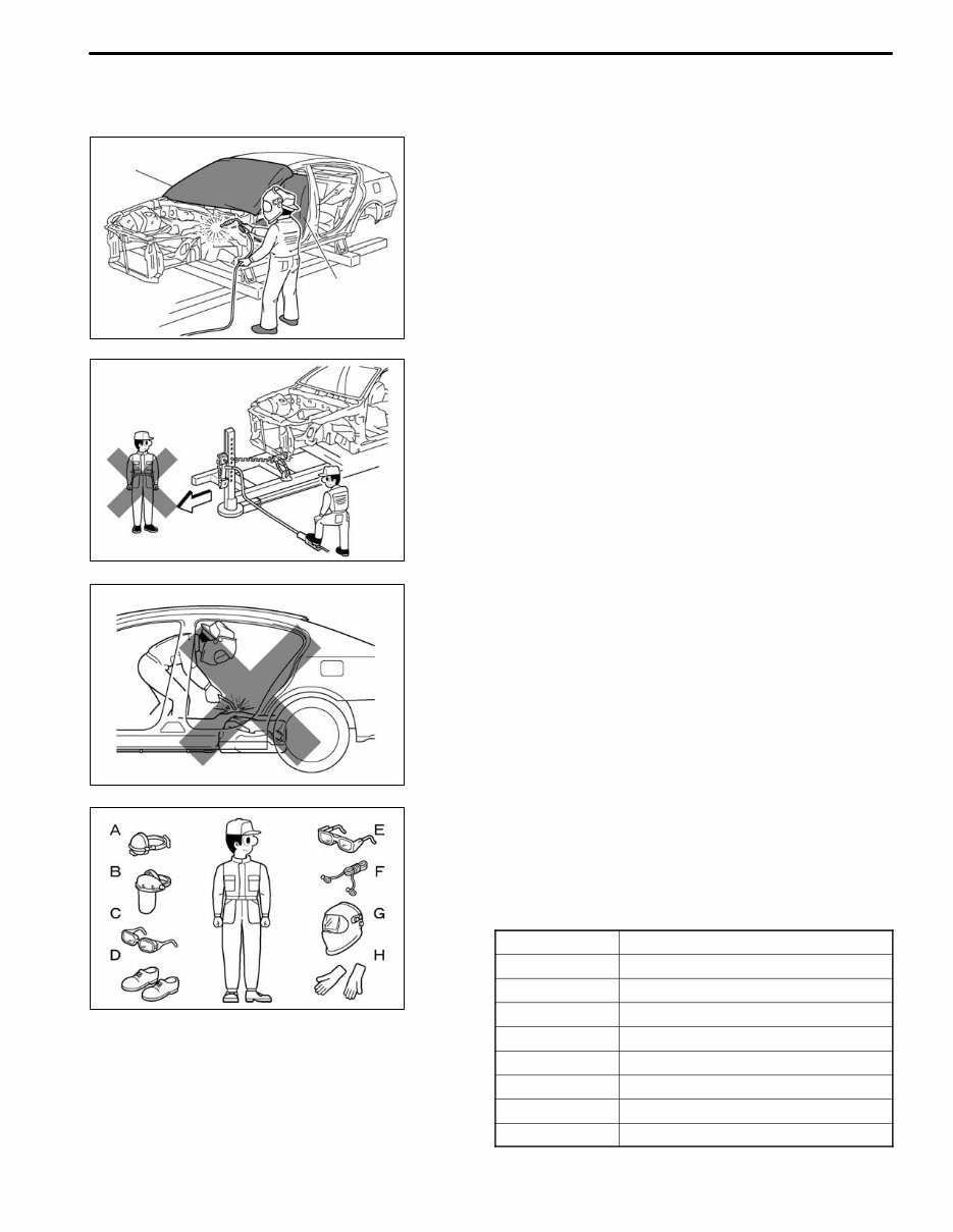
F33014 F33015 INTRODUCTION IN-2 2. PRECAUTIONS WHEN REPAIRING BODY FRAME PARTS (INCLUDING CRUSH BOX) (a) PROHIBITION OF HEAT REPAIR FOR BODY FRAME PARTS (1) Rustproof high strength steel sheets are used for the body frame. Therefore, if these parts are heat repaired using an acetylene torch or equiv- alent, the crystalline structure changes, causing the strength of the steel sheets to decrease. Also, the zinc coating which is used to protect the body from rust will be damaged. This causes the surface of the steel sheets to become oxi- dized, which reduces their ability to resist rust. (b) WHEN TO REPLACE FRAME PARTS NOTICE: Replace frame parts that have kinks. HINT: What is kink? A deformation on a steel sheet that cannot be re- turned to its original shape by pulling or hammering due to the deformation angle being sharp.
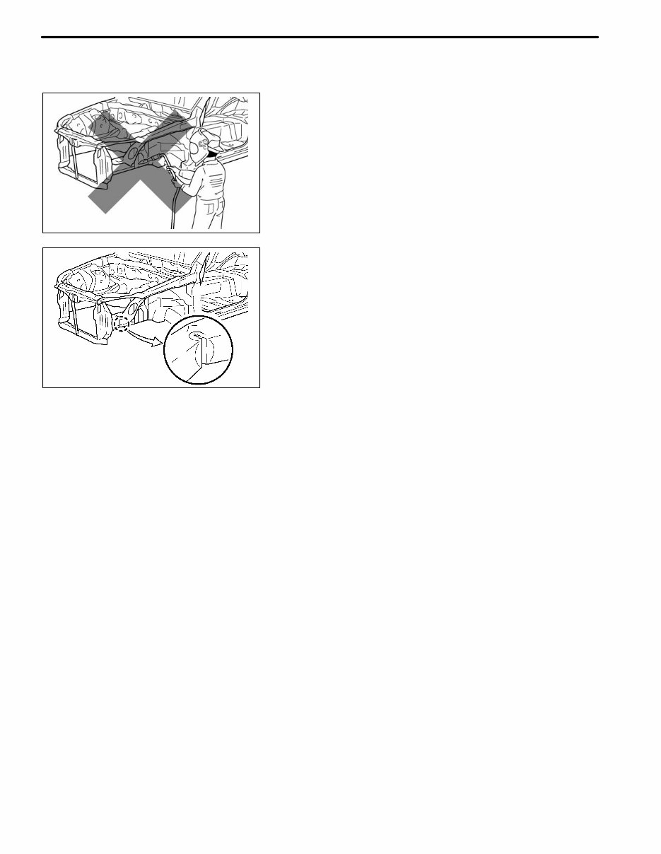
F30442 F33016 F33017 INTRODUCTION IN-3 (c) REPAIR OF DOOR SIDE IMPACT BEAM IS PROHIBITED (1) The impact beam is designed so that it performs at 100% in its original shape. However, if the impact beam is repaired, its per- formance may not be the same as before the ac- cident. PARTS WHICH ARE PROHIBITED TO BE RE- PAIRED: Door side impact beam (d) REPAIR OF BUMPER REINFORCEMENT IS PROHIBITED (1) The bumper reinforcement is designed so that it performs at 100% in its original shape. However, if the bumper reinforcement is re- paired, its performance may not be the same as before the accident. PARTS WHICH ARE PROHIBITED TO BE RE- PAIRED: Bumper reinforcement
INTRODUCTION F33007 F33008 F33009 Puncher F33010 Old Spot Locations New Spot Locations IN-4 3. PRECAUTIONS FOR CORRECT REPAIR (a) REMOVAL OF ADJACENT COMPONENTS (1) When removing adjacent components, apply protective tape to the surrounding body and your tools to prevent damage. NOTICE: If the paint film is damaged, make sure to re- finish the paint. (b) ANTI-RUST TREATMENT BEFORE WELDING (1) Apply welding primer to the contact surfaces of the welding areas to protect them from rust. NOTICE: Do not apply welding primer outside of the contact surfaces. (c) MAKING HOLES FOR PLUG WELDING (1) For areas where a spot welder cannot be used, use a puncher or drill to make holes for plug welding. Thickness of welded portion Diameter of plug hole Under 1.0 mm (0.04 in.) Over 5 mm (0.20 in.) 1.0 to 1.6 mm (0.04 to 0.06 in.) Over 6.5 mm (0.26 in.) 1.7 to 2.3 mm (0.07 to 0.09 in.) Over 8 mm (0.31 in.) Over 2.4 mm (0.09 in.) Over 10 mm (0.39 in.) (d) WELDING PRECAUTIONS (1) The number of welding spots should be as fol- lows. Spot weld: 1.3 X No. of manufacturer’s spots Plug weld: More than No. of manufacturer’s plugs (2) Spot weld locations Avoid welding over previously welded areas.
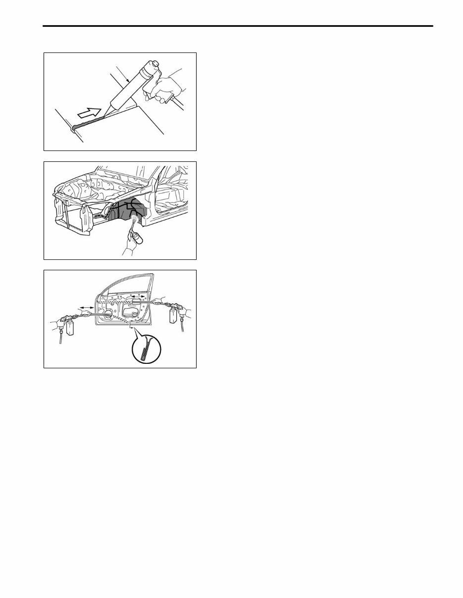
INTRODUCTION F33011 F33012 F33013 Sealer Gun IN-5 4. ANTI-RUST TREATMENT AFTER INSTALLATION (a) BODY SEALER APPLICATION PURPOSE: For water-proofing and anti-rust measures, always apply the body sealer to the body panel seams and hems of the doors, hood, etc. NOTICE: Apply body sealer neatly to parts that require a high quality appearance. (b) UNDERCOAT APPLICATION PURPOSE: To prevent corrosion and protect the body from grav- el, always apply a sufficient undercoating to the areas indicated. (c) VEHICLE BODY ANTI-RUST AGENT APPLICATION PURPOSE: The purpose is to protect areas from rust which are difficult to paint such as the backside of the box- shaped cross section frame parts. METHOD: Apply anti-rust agent through the service holes and/ or installation holes of the parts.
INTRODUCTION IN-6 5. PROCEDURES NECESSARY WHEN BATTERY TERMINAL IS DISCONNECTED/RECONNECTED (a) THE WORK LIST (1) Each inspection procedure refers to the TOYOTA Repair Manual. Necessary Procedures Procedure Details Effects/Inoperative Functions When Necessary Procedures are not Performed Notes Reset back door close position Fully close the back door to turn off the courtesy switch. S Power back door function S Back door closer function (w/ power back door system) S If the back door is closed when disconnecting the cable from the battery terminal, it is not neces- sary to reset it. S The power back door ECU controls the locked or unlocked state of the back door based on its memory. If the power for the power back door ECU is disconnected and reconnected, the back door will need to be unlocked before it can be operated. NOTICE: It may not be possible to release the steering lock or start the engine when the battery voltage is low. If this occurs, initialization of the steering lock system is required.
Whether you're a professional mechanic or a DIY enthusiast, this repair manual provides comprehensive troubleshooting and replacement procedures recommended by the manufacturer. It includes step-by-step instructions, clear images, and exploded-view illustrations to assist in fixing vehicle issues.
Regular maintenance is essential for the durability of your vehicle. Over time, certain parts will wear out and require replacement. This manual equips you with the manufacturer's recommended troubleshooting charts and replacement procedures, enabling you to save on repairs and enhance your vehicle's reliability.
Featuring clear images and detailed instructions, this manual eliminates the need to search through numerous pages for specific information. It offers a convenient alternative to traditional bound manuals, allowing easy access, search, and bookmarking. Additionally, it is printable for those who prefer a physical copy.
Format: .pdf Printable: Yes Language: English Compatibility: Compatible with various electronic devices, including PC, Mac, Android, and Apple devices. Requirements: Adobe Reader (free)