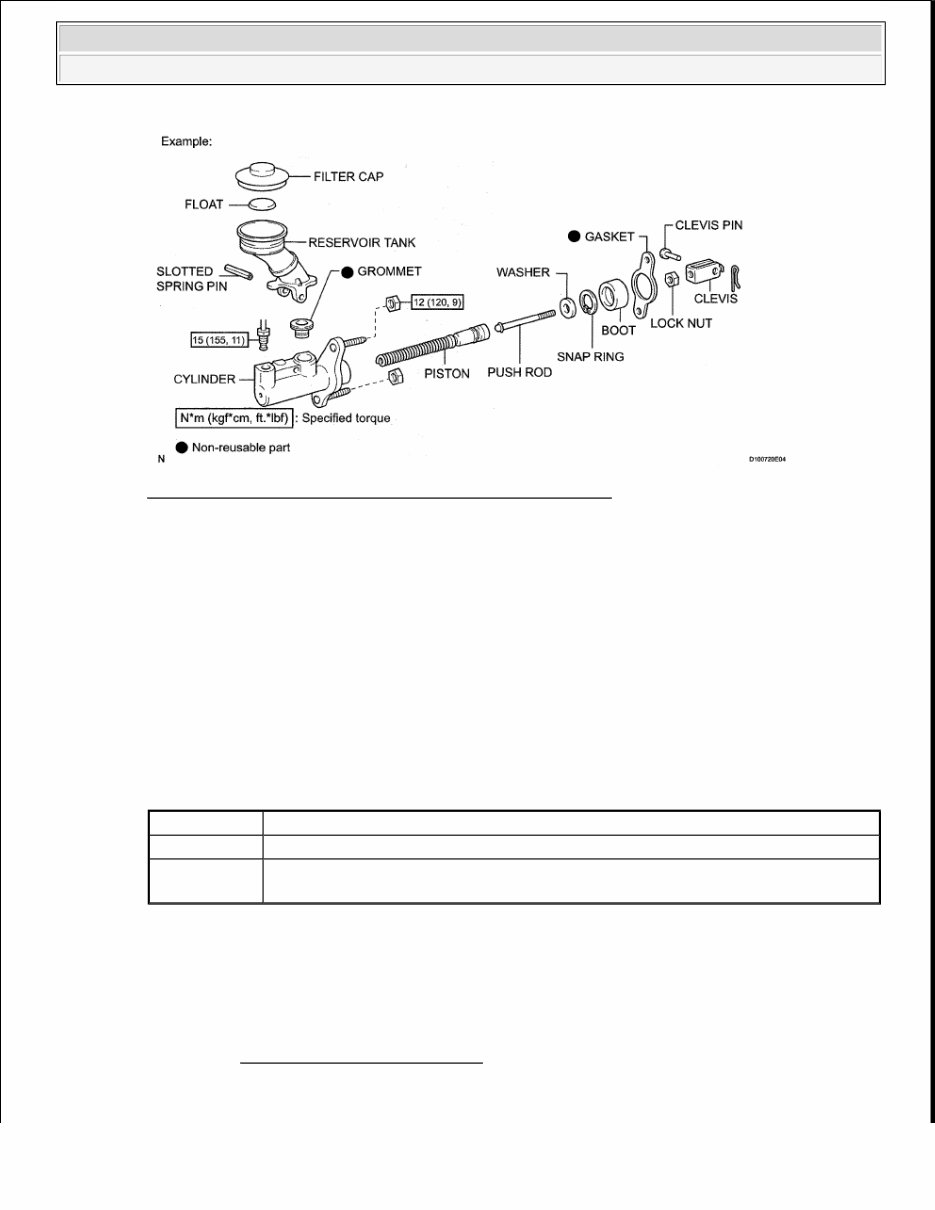
2009 GENERAL INFORMATION Introduction - Tundra HOW TO USE THIS INFORMATION GENERAL INFORMATION 1. GENERAL DESCRIPTION a. This article is written in accordance with SAE J2008. 1. Diagnosis 2. Removing/Installing, Replacing, Disassembling/Reassembling, Checking and Adjusting 3. Final Inspection b. The following procedures are omitted from this article. However, these procedures must be performed. 1. Use a jack or lift to perform operations 2. Clean all removed parts 3. Perform a visual check 2. PREPARATION a. Use of Special Service Tools (SST) and Special Service Materials (SSM) may be required, depending on the repair procedure. Be sure to use SST and SSM when they are required and follow the working procedure properly. A list of SST and SSM is in the PREPARATION article. 3. REPAIR PROCEDURES a. A component graphic is placed under the title where necessary. b. Non-reusable parts, grease application areas, precoated parts and torque specifications are noted in the component graphics. The following graphic is an example. 2009 Toyota Tundra 2009 GENERAL INFORMATION Introduction - Tundra
Fig. 1: Exploded View Of Parts With Torque Specifications Courtesy of TOYOTA MOTOR SALES, U.S.A., INC. c. Torque specifications, grease application areas and non-reusable parts are emphasized in the procedures. HINT: There are cases where such information can only be explained by using an graphic. In these cases, the information is described in the graphic. d. Only items with key points are described in the text. What to do and other details are explained using graphics next to the text. Both the text and graphics are accompanied by standard values and notices. GRAPHIC REFERENCE e. Graphics of similar vehicle models are sometimes used. In these cases, minor details may be different from the actual vehicle. f. Procedures are presented in a step-by-step format. 4. SERVICE SPECIFICATIONS a. SPECIFICATIONS are presented in boldface text throughout the article. The specifications are also found in the SERVICE SPECIFICATIONS article for reference. 5. TERM DEFINITIONS Graphic What to do and where to do it Task heading What work will be performed Explanation text How to perform the task Also has information such as specifications and warnings, which are written in boldface text 2009 Toyota Tundra 2009 GENERAL INFORMATION Introduction - Tundra
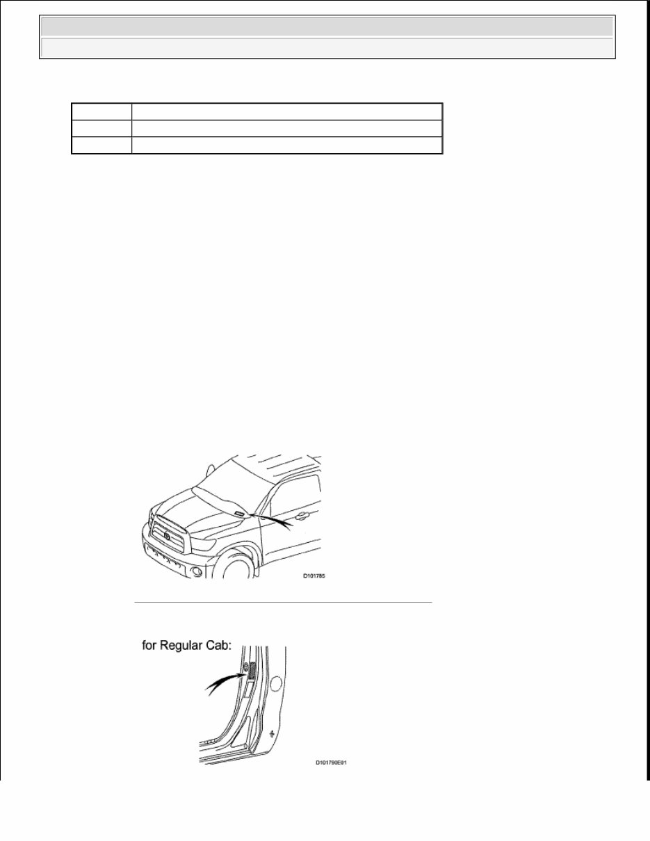
TERM DEFINITIONS 6. INTERNATIONAL SYSTEM OF UNITS a. The units used in this article comply with the International System of Units (SI) standard. Units from the metric system and the English systems are also provided. Example: Torque: 30 N*m (310 kgf*cm, 22 ft.*lbf) IDENTIFICATION INFORMATION VEHICLE IDENTIFICATION AND SERIAL NUMBERS 1. VEHICLE IDENTIFICATION NUMBER a. The vehicle identification number is stamped on the vehicle identification number plate and certification label, as shown below. 1. Vehicle Identification Number Plate 2. Certification Label Fig. 2: Identifying Vehicle Identification Number Plate Courtesy of TOYOTA MOTOR SALES, U.S.A., INC. CAUTION Possibility of injury to you or other people. NOTICE Possibility of damage to components being repaired. HINT Provides additional information to help you perform repairs. 2009 Toyota Tundra 2009 GENERAL INFORMATION Introduction - Tundra
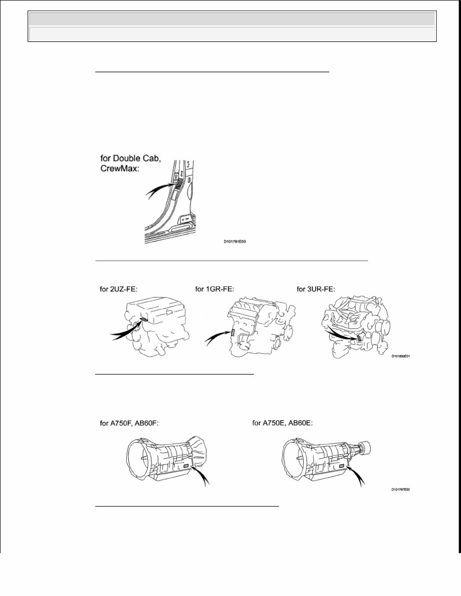
Fig. 3: Identifying Vehicle Certification Label (Regular Cab) Courtesy of TOYOTA MOTOR SALES, U.S.A., INC. 2. ENGINE SERIAL NUMBER AND TRANSMISSION SERIAL NUMBER a. The engine serial number is stamped on the cylinder block of the engine and the transmission serial number is stamped on the housing as shown below. 1. Engine Serial Number Fig. 4: Identifying Vehicle Certification Label (Double Cab, Crewmax) Courtesy of TOYOTA MOTOR SALES, U.S.A., INC. Fig. 5: Identifying Engine Serial Number Courtesy of TOYOTA MOTOR SALES, U.S.A., INC. 2. Transmission Serial Number Fig. 6: Identifying Transmission Serial Number Courtesy of TOYOTA MOTOR SALES, U.S.A., INC. REPAIR INSTRUCTION 2009 Toyota Tundra 2009 GENERAL INFORMATION Introduction - Tundra
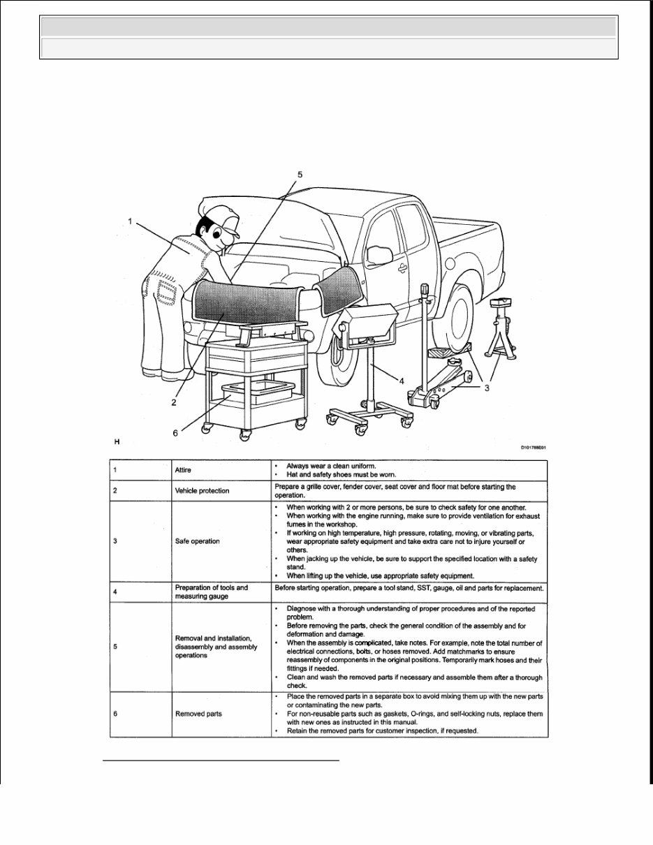
PRECAUTION 1. BASIC REPAIR HINT a. HINTS ON OPERATIONS Fig. 7: Identifying Basic Repair Operations Courtesy of TOYOTA MOTOR SALES, U.S.A., INC. 2009 Toyota Tundra 2009 GENERAL INFORMATION Introduction - Tundra
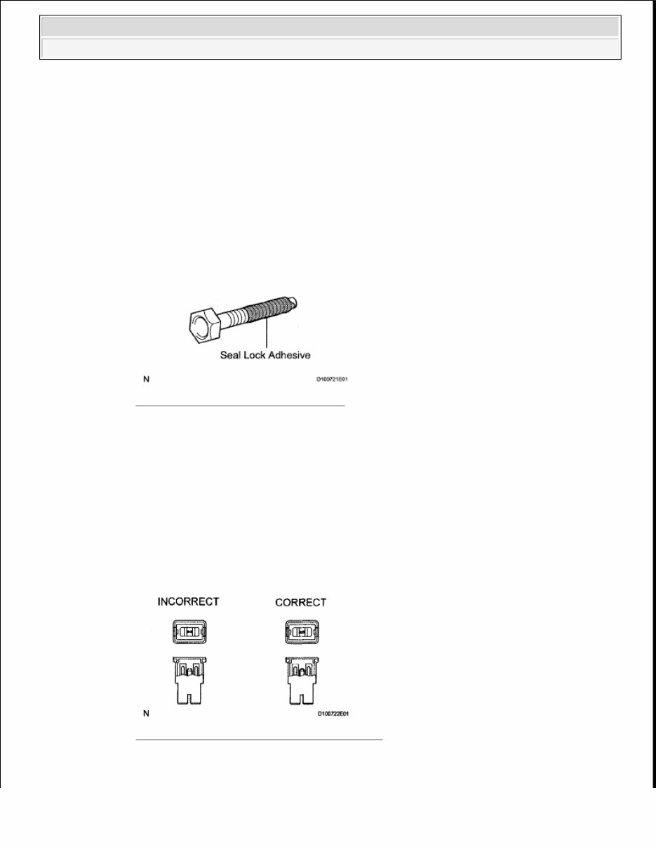
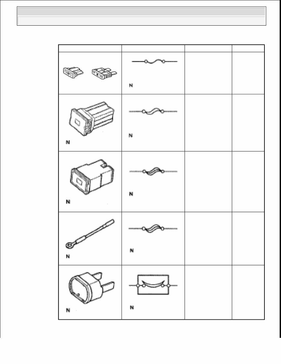
b. JACKING UP AND SUPPORTING VEHICLE 1. Care must be taken when jacking up and supporting the vehicle. Be sure to lift and support the vehicle at the proper locations. c. PRECOATED PARTS 1. Precoated parts are bolts and nuts that are coated with a seal lock adhesive at the factory. 2. If a precoated part is retightened, loosened or moved in any way, it must be recoated with the specified adhesive. 3. When reusing a precoated part, clean off the old adhesive and dry the part with compressed air. Then apply new seal lock adhesive appropriate to that part. 4. Some seal lock agents harden slowly. You may have to wait for the seal lock adhesive to harden. Fig. 8: Identifying Seal Lock Adhesive Courtesy of TOYOTA MOTOR SALES, U.S.A., INC. d. GASKETS 1. When necessary, use a sealer on gaskets to prevent leaks. e. BOLTS, NUTS AND SCREWS 1. Carefully follow all the specifications for tightening torques. Always use a torque wrench. f. FUSES 1. When inspecting a fuse, check that the wire of the fuse is not broken. 2. When replacing fuses, be sure that the new fuse has the correct amperage rating. Do not exceed the rating or use one with a lower rating. Fig. 9: Identifying Correct & Incorrect Fuses Courtesy of TOYOTA MOTOR SALES, U.S.A., INC. 2009 Toyota Tundra 2009 GENERAL INFORMATION Introduction - Tundra
PART DESCRIPTION TABLE g. clips Graphic Symbol Part Name Abbreviation FUSE FUSE MEDIUM CURRENT FUSE M-FUSE HIGH CURRENT FUSE H-FUSE FUSIBLE LINK FL CIRCUIT BREAKER CB 2009 Toyota Tundra 2009 GENERAL INFORMATION Introduction - Tundra
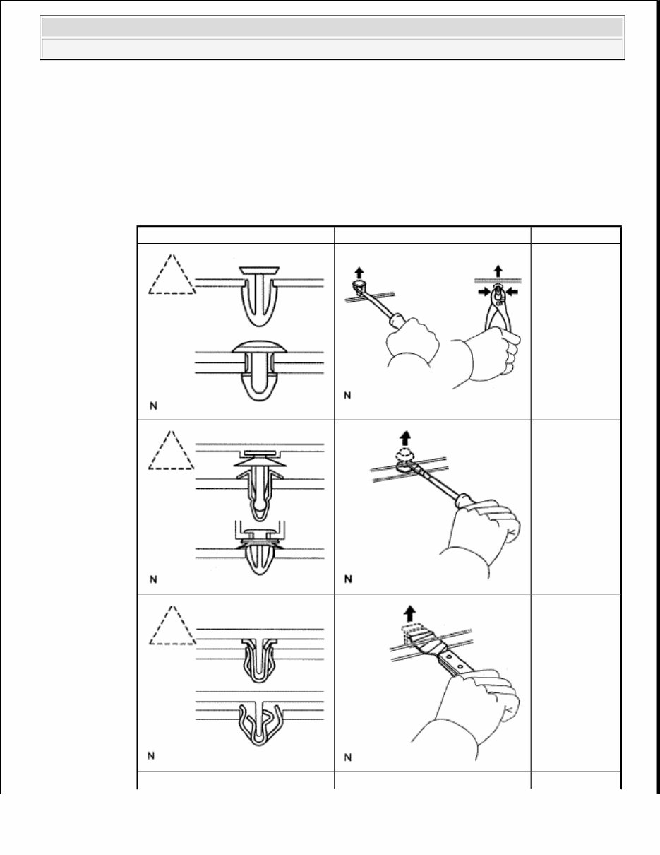
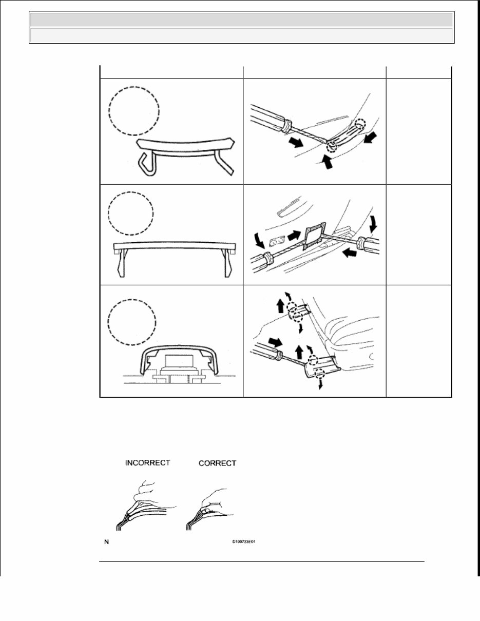
1. The removal and installation methods of typical clips used for vehicle body parts are shown in the table below. HINT: If clips are damaged during a procedure, always replace the clips with new clips. REMOVAL AND INSTALLATION METHODS OF TYPICAL CLIPS FOR VEHICLE BODY PARTS Shape (Example) Graphic Procedures Remove clips with a clip remover or pliers. Remove clips with a clip remover or screwdriver. Remove clips with a wide scraper to prevent panel damage. 2009 Toyota Tundra 2009 GENERAL INFORMATION Introduction - Tundra
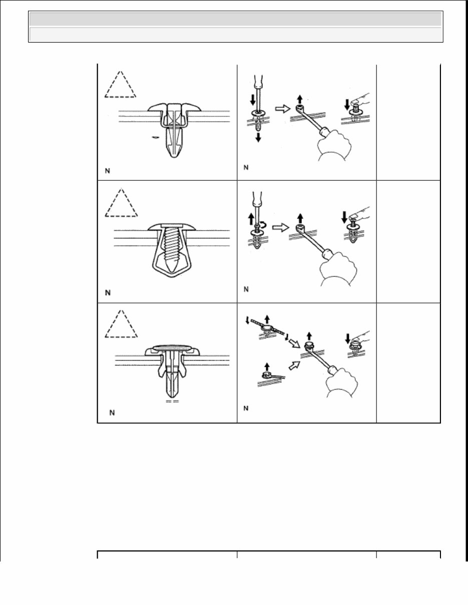
h. CLAWS 1. The removal and installation methods of typical claws used for vehicle body parts are shown in the table below. HINT: If claws of caps or covers are damaged during a procedure, always replace the caps or covers with new ones. REMOVAL AND INSTALLATION METHODS OF TYPICAL CLAWS FOR VEHICLE BODY PARTS Remove clips by pushing the center pin through and prying out the shell. Remove clips by unscrewing the center pin and prying out the shell. Remove clips by prying out the pin and then prying out the shell. 2009 Toyota Tundra 2009 GENERAL INFORMATION Introduction - Tundra
i. REMOVAL AND INSTALLATION OF VACUUM HOSES 1. To disconnect a vacuum hose, pull and twist from the end of the hose. Do not pull from the middle of the hose as this may cause damage. Fig. 10: Identifying Correct & Incorrect Method Of Disconnecting Vacuum Hose Courtesy of TOYOTA MOTOR SALES, U.S.A., INC. Shape (Example) Graphic Procedures Using a screwdriver, detach the claws and remove the caps or covers. Using a screwdriver, detach the claws and remove the caps or covers. Using a screwdriver, detach the claws and remove the caps or covers. 2009 Toyota Tundra 2009 GENERAL INFORMATION Introduction - Tundra
The 2009 Toyota Tundra Service & Repair Manual is a comprehensive guide covering procedures for routine maintenance, troubleshooting, and full mechanical repairs. Whether you're dealing with the 4.0L V6, the 4.7L V8, or the 5.7L V8, this manual is tailored to cover the specific procedures needed for each engine variant.
It walks you through everything from scheduled maintenance and brake service to engine teardown, transmission repair, suspension checks, and HVAC system diagnostics. You'll also find step-by-step instructions for working on the drivetrain, airbags, steering components, and emissions systems—exactly what you’d expect from an OEM manual.
Content overview:
General introduction and repair safety guidelines
Scheduled maintenance procedures and service intervals
Accessories and equipment troubleshooting and installation
Body and frame repair instructions, including structural components
Complete brake system service and component replacement
Driveline and axle diagnostics, including 4WD systems
Electrical system testing and wiring diagrams
Engine performance diagnostics and tuning procedures
Engine disassembly, inspection, and overhaul guides
HVAC system service, including heater and A/C components
Lighting system troubleshooting and bulb replacement
Airbag and restraint system diagnostics and repairs
Steering system repair and alignment procedures
Front and rear suspension service and component specs
Transmission service for automatic and manual gearboxes
Perfect for professional technicians and capable DIYers alike, this manual keeps things clear and to the point. If you’re looking to keep your Tundra running right, this guide provides the technical foundation to do it right the first time.
Printable: Yes Language: English Compatibility: Pretty much any electronic device, incl. PC & Mac computers, Android and Apple smartphones & tablet, etc. Requirements: Adobe Reader (free)