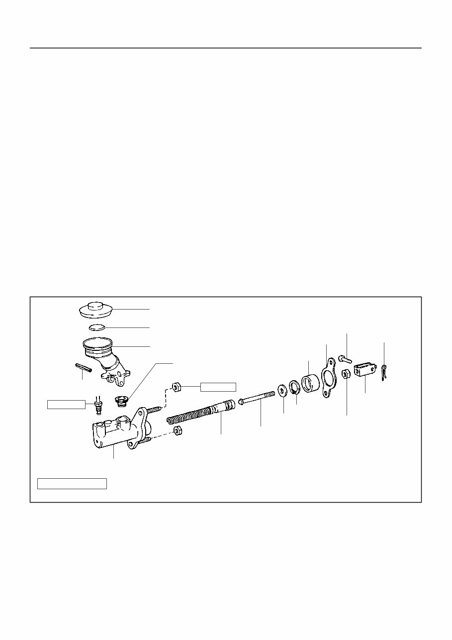
IN00U–36 N17080 Filler Cap Float Reservoir A Grommet Clip Slotted Spring Pin : Specified torque A Non–reusable part Cylinder Piston Push Rod Washer Snap Ring Boot A Gasket Lock Nut Clevis Pin Clevis N·m (kgf·cm, ft·lbf) 12 (120, 9) 15 (155, 11) – INTRODUCTION HOW TO USE THIS MANUAL IN–1 1 AuthorĂ: DateĂ: 2003 TOYOTA TUNDRA (RM956U) HOW TO USE THIS MANUAL GENERAL INFORMATION 1. INDEX An INDEX is provided on the first page of each section to guide you to the item to be repaired. To assist you in finding your way through the manual, the section title and major heading are given at the top of every page. 2. PRECAUTION At the beginning of each section, a PRECAUTION is given that pertains to all repair operations contained in that section. Read these precautions before starting any repair task. 3. TROUBLESHOOTING TROUBLESHOOTING tables are included for each system to help you diagnose the problem and find the cause. The fundamentals of how to proceed with troubleshooting are described on page IN–17. Be sure to read this before performing troubleshooting. 4. PREPARATION Preparation lists the SST (Special Service Tools), recommended tools, equipment, lubricant and SSM (Spe- cial Service Materials) which should be prepared before beginning the operation and explains the purpose of each one. 5. REPAIR PROCEDURES Most repair operations begin with an overview illustration. It identifies the components and shows how the parts fit together. Example:
Illustration: what to do and where 21. CHECK PISTON STROKE OF OVERDRIVE BRAKE (a) Task heading : what to do SST 09350–30020 (09350–06120) Set part No. Component part No. Detailed text : how to do task (b) Piston stroke: 1.40 Ċ 1.70 mm (0.0551 Ċ 0.0669 in.) Specification Place SST and a dial indicator onto the overdrive brake pis- ton as shown in the illustration. Measure the stroke applying and releasing the compressed air (392 Ċ 785 kPa, 4 Ċ 8 kgf/cm 2 or 57 Ċ 114 psi) as shown in the illustration. IN–2 – INTRODUCTION HOW TO USE THIS MANUAL 2 AuthorĂ: DateĂ: 2003 TOYOTA TUNDRA (RM956U) The procedures are presented in a step–by–step format: Y The illustration shows what to do and where to do it. Y The task heading tells what to do. Y The detailed text tells how to perform the task and gives other information such as specifications and warnings. Example: This format provides the experienced technician with a FAST TRACK to the information needed. The upper case task heading can be read at a glance when necessary, and the text below it provides detailed informa- tion. Important specifications and warnings always stand out in bold type. 6. REFERENCES References have been kept to a minimum. However, when they are required you are given the page to refer to. 7. SPECIFICATIONS Specifications are presented in bold type throughout the text where needed. You never have to leave the procedure to look up your specifications. They are also found in Service Specifications section for quick ref- erence. 8. CAUTIONS, NOTICES, HINTS: Y CAUTIONS are presented in bold type, and indicate there is a possibility of injury to you or other people. Y NOTICES are also presented in bold type, and indicate the possibility of damage to the components being repaired. Y HINTS are separated from the text but do not appear in bold. They provide additional information to help you perform the repair efficiently. 9. SI UNIT The UNITS given in this manual are primarily expressed according to the SI UNIT (International System of Unit), and alternately expressed in the metric system and in the English System. Example: Torque: 30 N·m (310 kgf·cm, 22 ft·lbf)
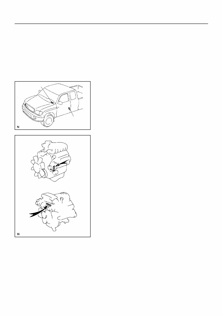
IN01P–04 B02417 A B B02418 5VZ–FE Engine 2UZ–FE Engine – INTRODUCTION IDENTIFICATION INFORMATION IN–3 3 AuthorĂ: DateĂ: 2003 TOYOTA TUNDRA (RM956U) IDENTIFICATION INFORMATION VEHICLE IDENTIFICATION AND ENGINE SERIAL NUMBER 1. VEHICLE IDENTIFICATION NUMBER The vehicle identification number is stamped on the vehicle identification number plate and certification label. A: Vehicle Identification Number Plate B: Certification Label 2. ENGINE SERIAL NUMBER The engine serial number is stamped on the engine block, as shown in the illustration.
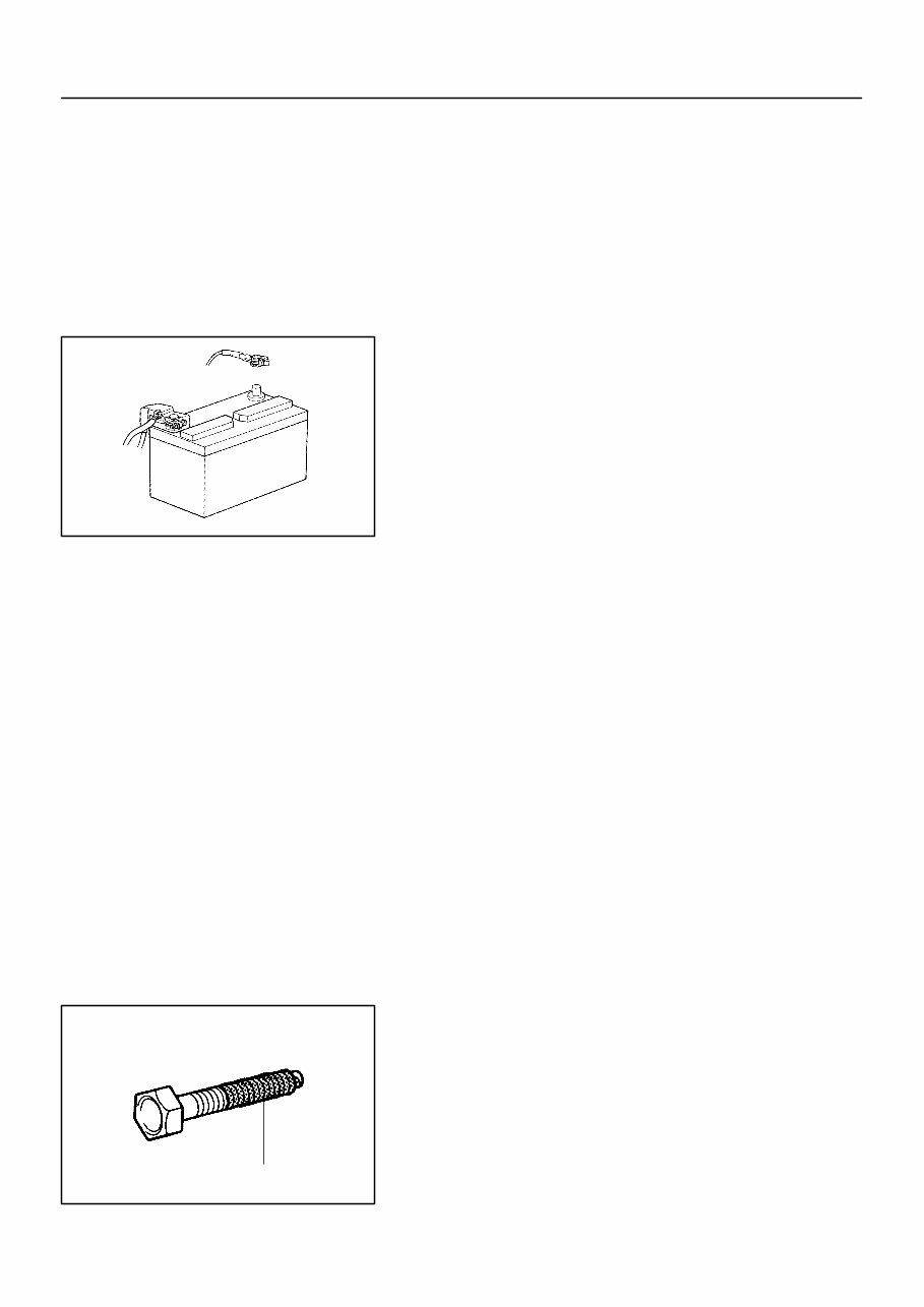
IN0CO–12 FI1066 Z11554 Seal Lock Adhesive IN–4 – INTRODUCTION REPAIR INSTRUCTIONS 4 AuthorĂ: DateĂ: 2003 TOYOTA TUNDRA (RM956U) REPAIR INSTRUCTIONS GENERAL INFORMATION BASIC REPAIR HINT (a) Use fender, seat and floor covers to keep the vehicle clean and prevent damage. (b) During disassembly, keep parts in the appropriate order to facilitate reassembly. (c) Installation and removal of battery terminal: (1) Before performing electrical work, disconnect the negative (–) terminal cable from the battery. (2) If it is necessary to disconnect the battery for in- spection or repair, first disconnect the negative (–) terminal cable. (3) When disconnecting the terminal cable, to prevent damage to battery terminal, loosen the cable nut and raise the cable straight up without twisting or prying it. (4) Clean the battery terminals and cable ends with a clean shop rag. Do not scrape them with a file or oth- er abrasive objects. (5) Install the cable ends to the battery terminals after loosening the nut, and tighten the nut after installa- tion. Do not use a hammer to tap the cable ends onto the terminals. (6) Be sure the cover for the positive (+) terminal is properly in place. (d) Check hose and wiring connectors to make sure that they are connected securely and correctly. (e) Non–reusable parts (1) Always replace cotter pins, gaskets, O–rings, oil seals, etc. with new ones. (2) Non–reusable parts are indicated in the component illustrations by the ” ” symbol. (f) Precoated parts Precoated parts are bolts, nuts, etc. that are coated with a seal lock adhesive at the factory. (1) If a precoated part is retightened, loosened or caused to move in any way, it must be recoated with the specified adhesive. (2) When reusing precoated parts, clean off the old adhesive and dry with compressed air. Then apply the specified seal lock adhesive to the bolt, nut or threads.
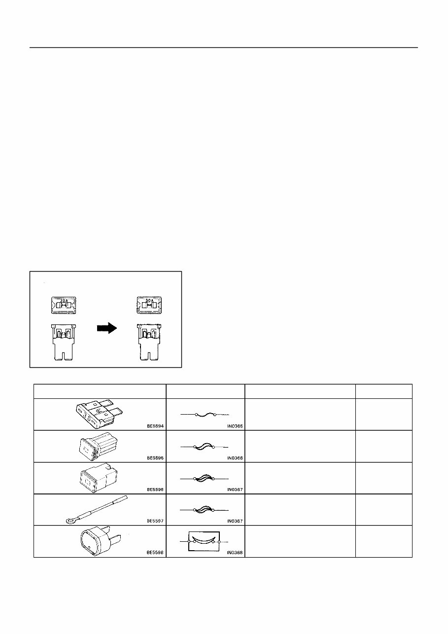
BE1367 Medium Current Fuse and High Current Fuse Equal Amperage Rating V00076 Abbreviation Part Name Symbol Illustration FUSE MEDIUM CURRENT FUSE HIGH CURRENT FUSE FUSIBLE LINK CIRCUIT BREAKER FUSE M–FUSE H–FUSE FL CB – INTRODUCTION REPAIR INSTRUCTIONS IN–5 5 AuthorĂ: DateĂ: 2003 TOYOTA TUNDRA (RM956U) (3) Precoated parts are indicated in the component il- lustrations by the ”Y” symbol. (g) When necessary, use a sealer on gaskets to prevent leaks. (h) Carefully observe all specifications for bolt tightening torques. Always use a torque wrench. (i) Use of special service tools (SST) and special service ma- terials (SSM) may be required, depending on the nature of the repair. Be sure to use SST and SSM where speci- fied and follow the proper work procedure. A list of SST and SSM can be found in Preparation section in this manual. (j) When replacing fuses, be sure the new fuse has the cor- rect amperage rating. DO NOT exceed the rating or use one with a lower rating.
You're Reading a Preview
What's Included?
Lifetime Access
Fast Download Speeds
Offline Viewing
Access Contents & Bookmarks
Full Search Facility
Print one or all pages of your manual
$24.99
2000-2006 Toyota Tundra OEM Service & Repair Manual
2000-2006 Toyota Tundra OEM Service & Repair Manual
Engines covered:
3.4L 5VZ-FE V6
4.7L 2UZ-FE V8
4.0L 1GR-FE V6
The 2000-2006 Toyota Tundra OEM Service & Repair Manual is the official workshop reference for first-generation Tundras equipped with the 3.4L V6, 4.7L V8, and later 4.0L V6 engines. Whether you're in a shop setting or spinning wrenches at home, this manual provides clear, factory-level procedures across all critical systems.
Inside, you’ll find complete engine mechanical service for both V6 and V8 variants, plus detailed coverage of cooling, ignition, lubrication, and emissions systems. Transmission sections walk through both automatic and manual rebuilds, while additional chapters cover suspension, steering gear adjustments, brake servicing, and SRS diagnostics. There's also in-depth support for fuel injection, A/C servicing, and drivetrain repair—including VF2A and VF2BM transfer cases.
Content overview:
General introduction, service precautions, and maintenance intervals
Detailed preparation procedures and factory service specifications
Air conditioning system service and diagnostics
Supplemental Restraint System (SRS) procedures
Automatic and manual transmission disassembly and repair
Engine mechanical, cooling, ignition, lubrication, and emission control systems (V6 & V8 engines covered separately)
Starting, charging, and fuel injection (SFI) systems for both V6 and V8 engines
Full diagnostics and troubleshooting sections
Braking system, ABS components, and hydraulic servicing
Propeller shaft, suspension, and axle servicing
Steering gear overhaul and adjustment
Transfer case (VF2A & VF2BM) servicing
Bodywork, interior, and exterior repair procedures
Electrical system overview, wiring diagrams, relay locations, and circuit troubleshooting
System circuits, ground points, power sources, and connector lists
Glossary of terms, abbreviations, and part number charts for connectors
From regular maintenance intervals to full drivetrain tear-downs, this manual is great for pros and experienced DIYers looking to keep a 2000-2006 Tundra in solid shape.
Printable: Yes Language: English Compatibility: Pretty much any electronic device, incl. PC & Mac computers, Android and Apple smartphones & tablet, etc. Requirements: Adobe Reader (free)
Reviews
Q&A
Recently Viewed
5,521,897Happy Clients
2,594,462eManuals
1,120,453Trusted Sellers
15Years in Business
Price:
Actual Price:
2000-2006 Toyota Tundra OEM Service & Repair Manual