2009 ACCESSORIES & EQUIPMENT
Park Assist / Monitoring - Tacoma
REAR VIEW MONITOR SYSTEM
ARTS LOCATION
2009 Toyota Tacoma
2009 ACCESSORIES & EQUIPMENT Park Assist / Monitoring - Tacoma
2009 Toyota Tacoma
2009 ACCESSORIES & EQUIPMENT Park Assist / Monitoring - Tacoma
Saturday, September 27, 2014 12:39:07 PM Page 1 © 2011 Mitchell Repair Information Company, LLC. Saturday, September 27, 2014 12:39:11 PM Page 1 © 2011 Mitchell Repair Information Company, LLC.
2009 Toyota Tacoma
2009 ACCESSORIES & EQUIPMENT Park Assist / Monitoring - Tacoma
Saturday, September 27, 2014 12:39:08 PM Page 2 © 2011 Mitchell Repair Information Company, LLC.
Fi g . 1: Identif y in g Rear View Monitor S y stem Parts Location
Courtesy of TOYOTA MOTOR SALES, U.S.A., INC.
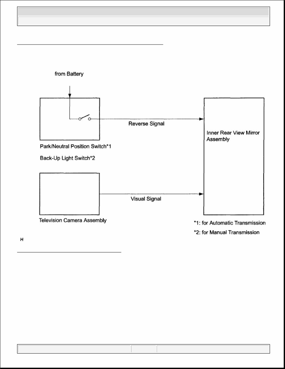
SYSTEM DIAGRAM
Fig. 2: Rear View Monitor System Diagram
Courtesy of TOYOTA MOTOR SALES, U.S.A., INC.
SYSTEM DESCRIPTION
1. GENERAL
a. To assist the driver with parking the vehicle by displaying an image of the area behind the vehicle,
this system has a television camera mounted on the tailgate. The system displays the image on the
inner rear view mirror assembly.
b. This system consists of the following components:
1. Inner rear view mirror assembly
2. Television camera assembly
3. Park/neutral position switch*1
2009 Toyota Tacoma
2009 ACCESSORIES & EQUIPMENT Park Assist / Monitoring - Tacoma
Saturday, September 27, 2014 12:39:08 PM Page 3 © 2011 Mitchell Repair Information Company, LLC.
4. Back-up light switch*2
*1: for Automatic Transmission
*2: for Manual Transmission
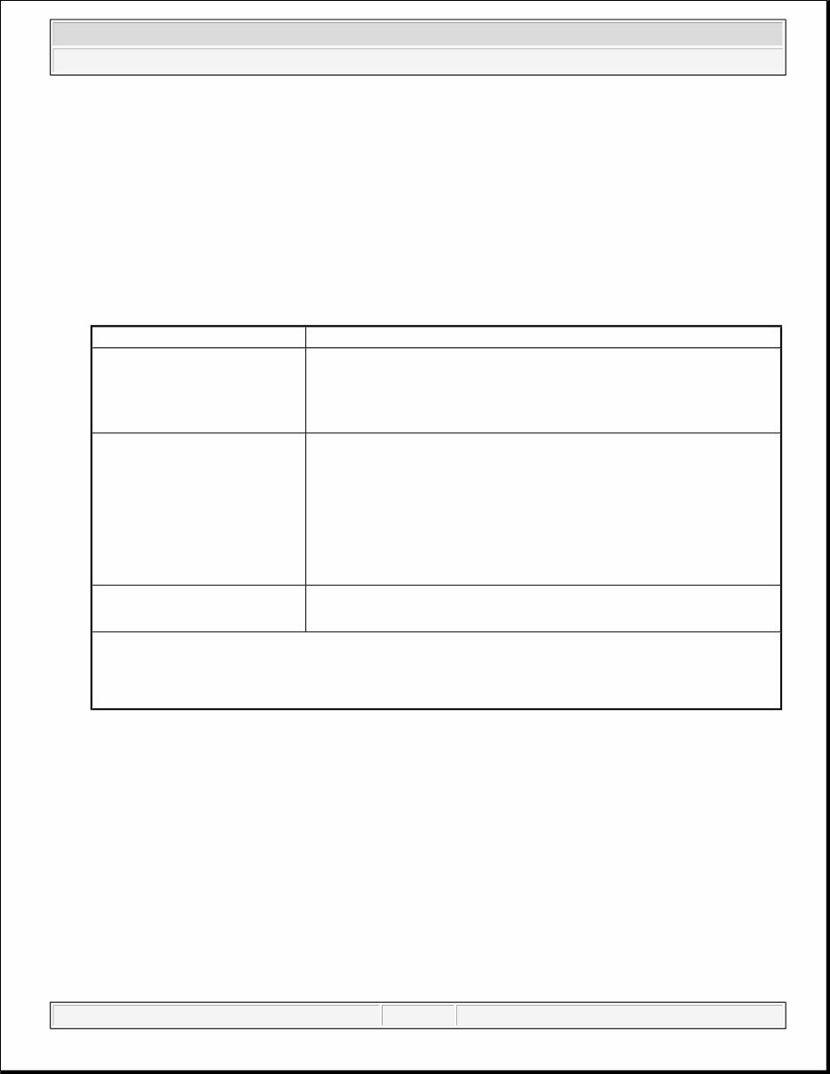
2. FUNCTION OF COMPONENTS
a. The inner rear view mirror assembly controls the system by using information from the following
components:
COMPONENTS FUNCTION
3. OPERATION EXPLANATION
a. The inner rear view mirror assembly receives the R position signal from the park/neutral position
switch or back-up light switch when the shift lever is moved to the R position. After receiving the
R position signal, the inner rear view mirror displays the rear camera image.
4. NOTES FOR REAR VIEW MONITOR
a. Notes for the rear view monitor.
1. The rear view monitor may not function properly if subjected to a severe blow by any hard
object.
2. Do not scrub the cover part of the camera (plastic). Scrubbing it may scratch the cover and
affect the image. Prevent organic solvents, waxes, bond removing solvents, or glass coating
from adhering to the cover. If such material adheres to the cover, clean it off immediately and
wash with water.
Item Function
Television Camera Assembly
Mounted on the tailgate to transmit an image of the area behind
the vehicle to the inner rear view mirror assembly.
A color video camera that uses a CCD (Charge Coupled Device)
and a wide-angle lens.
Inner rear view mirror assembly
Receive video signals, which contain images of the area behind
the vehicle, taken with the television camera assembly.
Performs control of the system by receiving the shift position
signal from the park/neutral position switch
(1)
1 or the back-up
light switch
(2)
.
Displays the rear view monitor image on the inner rear view
mirror.
Park/Neutral Position Switch
(1)
1 Back-Up Light Switch
(2)
Transmits a reverse shift position signal to the inner rear view mirror
assembly.
(1)
for Automatic Transmission
(2)
for Manual Transmission
2009 Toyota Tacoma
2009 ACCESSORIES & EQUIPMENT Park Assist / Monitoring - Tacoma
Saturday, September 27, 2014 12:39:08 PM Page 4 © 2011 Mitchell Repair Information Company, LLC.
3. Exposing the camera to a sudden temperature change may cause the camera to function
improperly.
4. A clear image may not appear if the camera is dirty with snow, mud, etc. In that case, wash it
with water and wipe off the lens. Use a detergent to remove dirt if necessary.
b. Images are difficult to discern even in normal conditions if:
1. The camera screen is frosted over (the image immediately after turning the ignition switch to
ON may be blurred or darker than normal).
2. A strong beam of light, such as a sunbeam or headlight, shines on the camera.
3. The vehicle is in a dark area (at night, etc.).
4. The ambient temperature around the camera is either too high or too low.
HINT:
When a strong light, such as a sunbeam reflected from another vehicles body, shines on the
camera, the image may be blurred. This is called "smear" and is common for the CCD
camera.
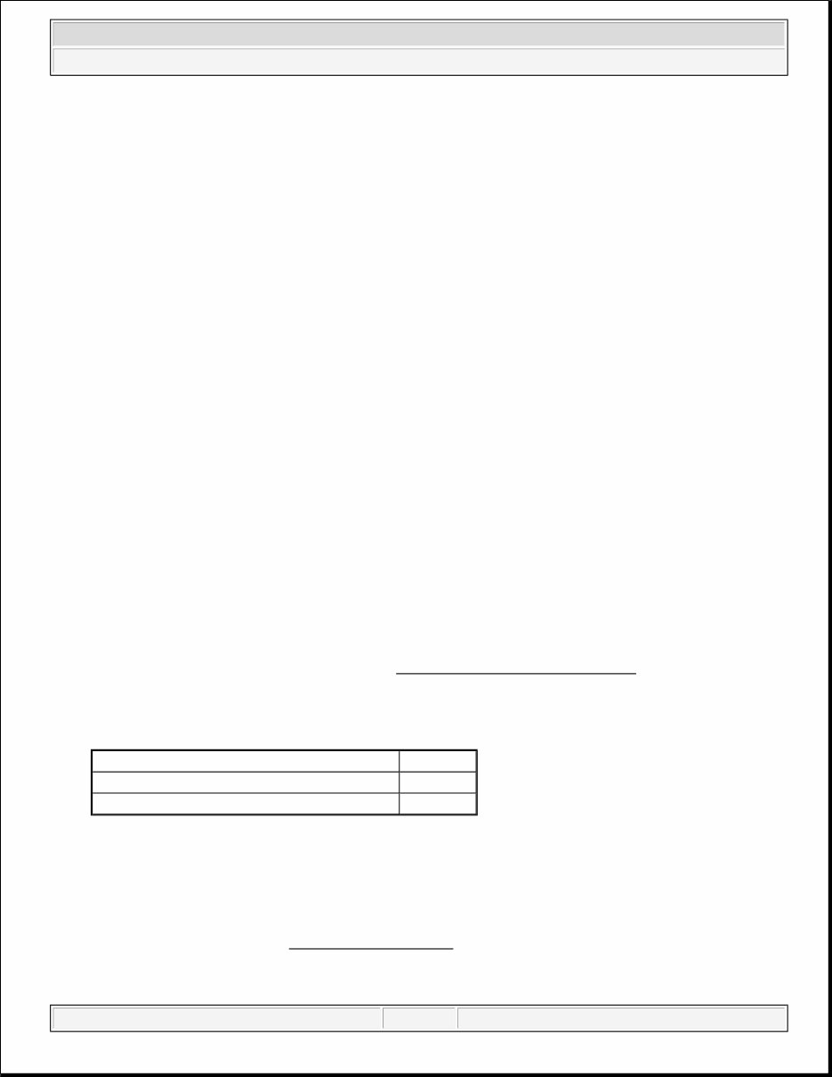
HOW TO PROCEED WITH TROUBLESHOOTING
HINT:
Use these procedures to troubleshoot the rear view monitor system.
1. VEHICLE BROUGHT TO WORKSHOP
2. CUSTOMER PROBLEM ANALYSIS
3. PROBLEM SYMPTOM CONFIRMATION
4. PROBLEM SYMPTOMS TABLE
a. Refer to Problem Symptoms Table (See PROBLEM SYMPTOMS TABLE ).
Result
RESULT REFERENCE
B: Go to step 6
A: Go to Next Step
5. BASED ON PROBLEM SYMPTOM, PERFORM TROUBLESHOOTING BELOW
a. Terminals of ECU (See TERMINALS OF ECU ).
6. ADJUST, REPAIR OR REPLACE
Result Proceed to
Fault is not listed in Problem Symptoms Table A
Fault is listed in Problem Symptoms Table B
2009 Toyota Tacoma
2009 ACCESSORIES & EQUIPMENT Park Assist / Monitoring - Tacoma
Saturday, September 27, 2014 12:39:08 PM Page 5 © 2011 Mitchell Repair Information Company, LLC.
7. CONFIRMATION TEST
NEXT: END
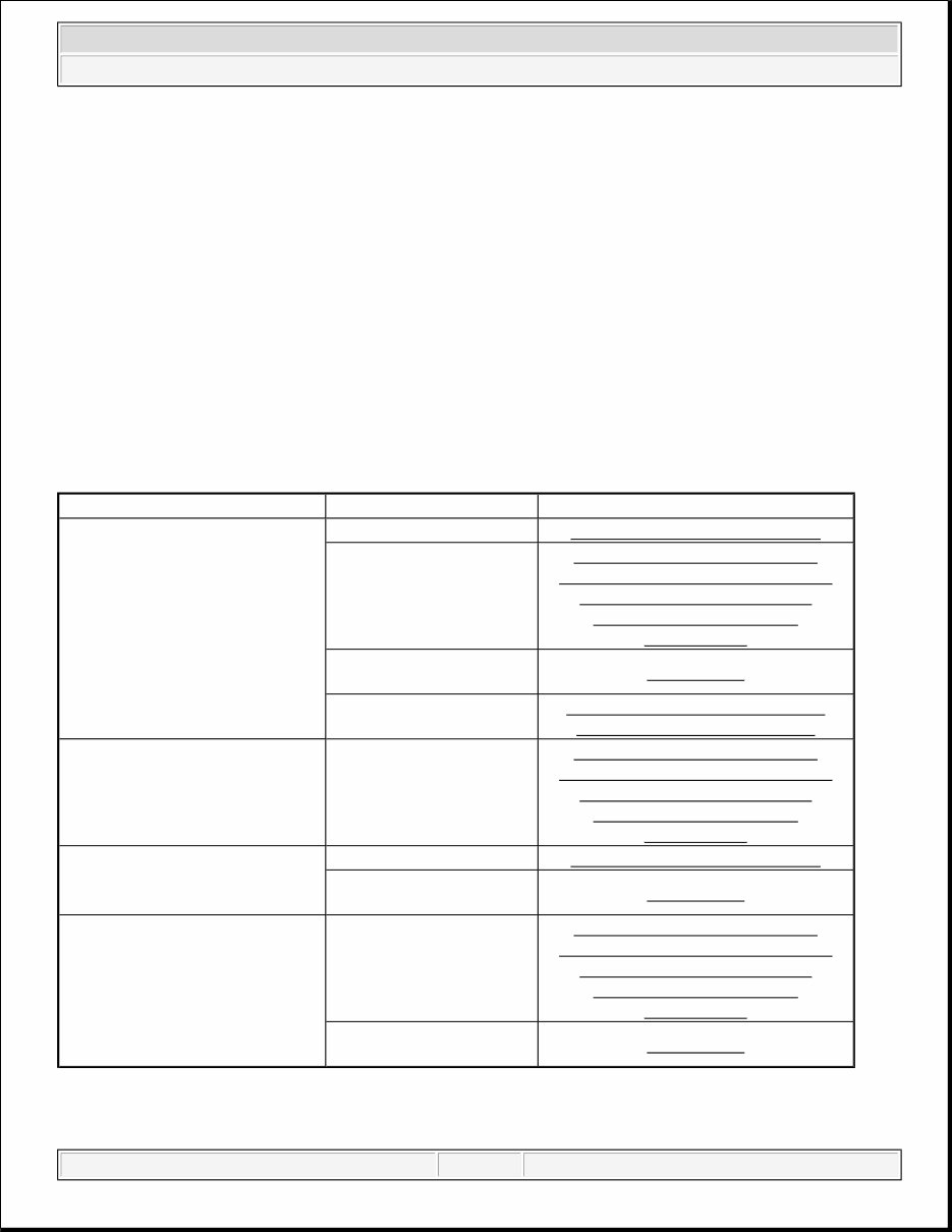
PROBLEM SYMPTOMS TABLE
HINT:
Use the table below to help determine the cause of problem symptoms. If multiple suspected areas are
listed, the potential causes of the symptoms are listed in order of probability in the "Suspected Area"
column of the table. Check each symptom by checking the suspected areas in the order they are listed.
Replace parts as necessary.
Inspect the fuses and relays related to this system before inspecting the suspected areas below.
Rear View Monitor System
PROBLEM SYMPTOMS CHART
HINT:
Symptom Suspected Area Refer to
When shift lever is in R position,
rear view monitor image is not
displayed.
Reverse signal circuit REVERSE SIGNAL CIRCUIT
Display signal circuit
between inner rear view
mirror assembly and
television camera assembly
DISPLAY SIGNAL CIRCUIT
BETWEEN INNER REAR VIEW
MIRROR ASSEMBLY AND
TELEVISION CAMERA
ASSEMBLY
Inner rear view mirror
assembly
REMOVAL
Inner rear view mirror
power source circuit
INNER REAR VIEW MIRROR
POWER SOURCE CIRCUIT
When shift lever is in R position,
rear view monitor image is not
displayed (Screen is blue for 3
seconds and then disappears).
Display signal circuit
between inner rear view
mirror assembly and
television earners assembly
DISPLAY SIGNAL CIRCUIT
BETWEEN INNER REAR VIEW
MIRROR ASSEMBLY AND
TELEVISION CAMERA
ASSEMBLY
When shift lever is not in R
position, rear view monitor image
is displayed.
Reverse signal circuit REVERSE SIGNAL CIRCUIT
Inner rear view mirror
assembly
REMOVAL
Problem with the rear view
monitor image (color, disorder of
picture).
Display signal circuit
between inner rear view
mirror assembly and
television camera assembly
DISPLAY SIGNAL CIRCUIT
BETWEEN INNER REAR VIEW
MIRROR ASSEMBLY AND
TELEVISION CAMERA
ASSEMBLY
Inner rear view mirror
assembly
REMOVAL
2009 Toyota Tacoma
2009 ACCESSORIES & EQUIPMENT Park Assist / Monitoring - Tacoma
Saturday, September 27, 2014 12:39:08 PM Page 6 © 2011 Mitchell Repair Information Company, LLC.
When the amber LED light is illuminated on the inner rear view mirror assembly with the ignition switch ON
and the shift lever position R, this indicates that the monitor image has been canceled manually. Check if the
image will be displayed by pressing the AUTO button.
TERMINALS OF ECU
1. TELEVISION CAMERA ASSEMBLY
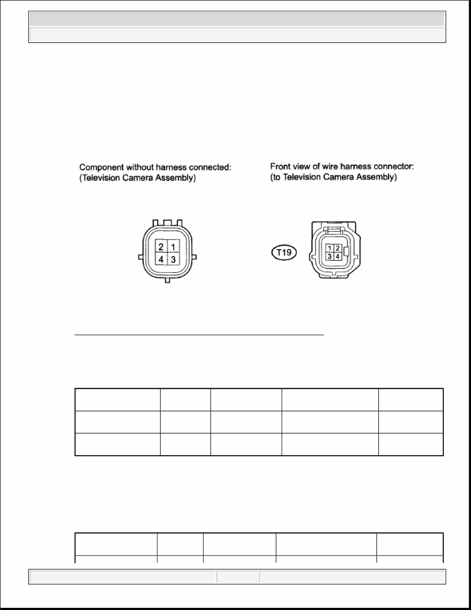
a. Disconnect the T19 television camera assembly connector.
Fig. 3: Identifying T19 Television Camera Assembly Connector
Courtesy of TOYOTA MOTOR SALES, U.S.A., INC.
b. Measure the voltage according to the value(s) in the table below.
CONNECTOR TERMINAL REFERENCE
If the result is not as specified, there may be a malfunction on the wire harness side.
c. Reconnect the T19 television camera assembly connector.
d. Measure the waveform according to the value(s) in the table below.
CONNECTOR TERMINAL REFERENCE
Terminal No.
(Symbol)
Wiring
Color
Terminal
Description
Condition
Specified
Condition
T19-3 (CGND) -
Body ground
L - Body
ground
Ground Always Below 1 V
T19-4 (CB+) - T19-3
(CGND)
B - L Power source
Ignition switch ON, shift
lever in R
5.5 to 7.05 V
Terminal No.
(Symbol)
Wiring
Color
Terminal
Description
Condition
Specified
Condition
2009 Toyota Tacoma
2009 ACCESSORIES & EQUIPMENT Park Assist / Monitoring - Tacoma
Saturday, September 27, 2014 12:39:08 PM Page 7 © 2011 Mitchell Repair Information Company, LLC.
If the result is not as specified, the camera may have a malfunction.
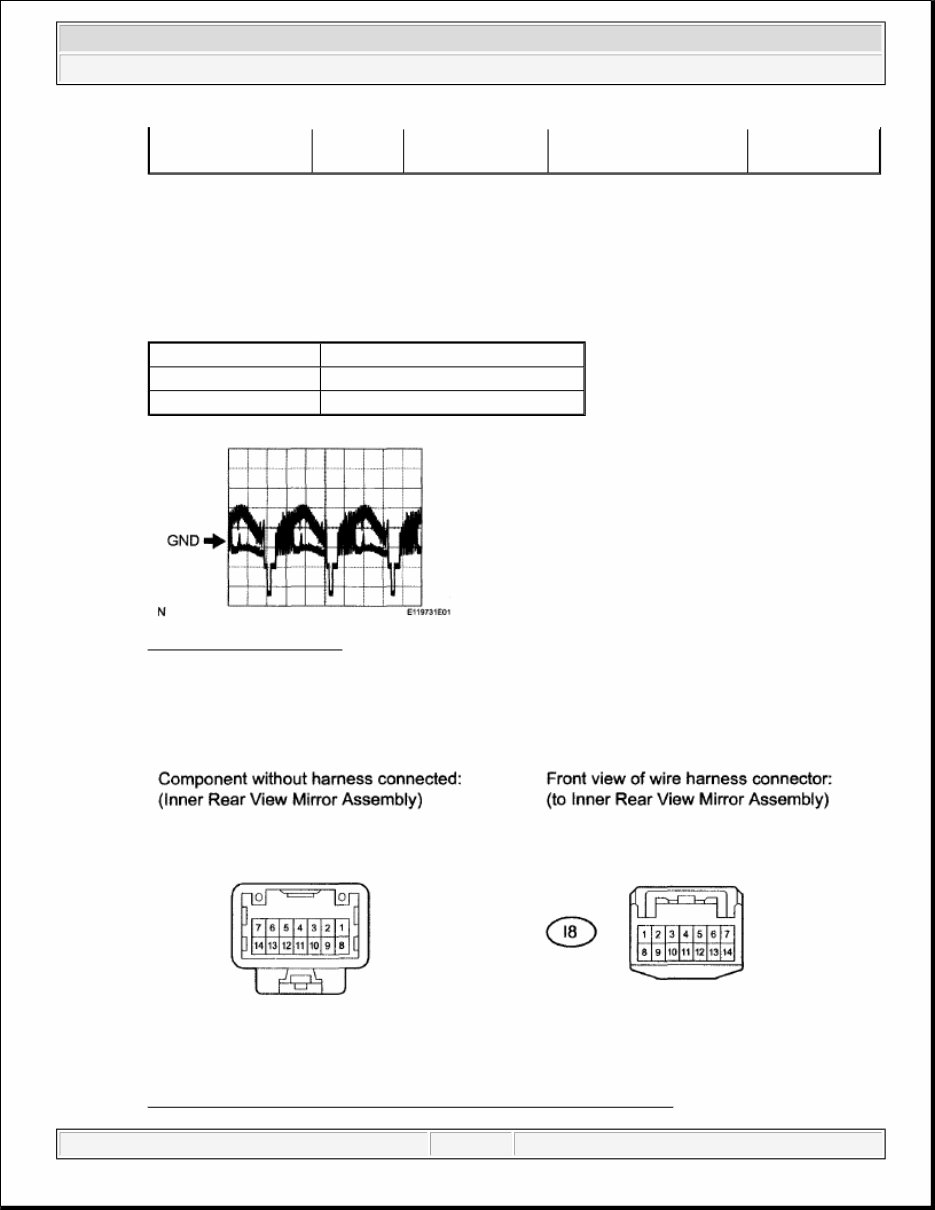
e. Using an oscilloscope, check the waveform.
Waveform (Reference)
WAVEFORM REFERENCE CHART
Fig. 4: Waveform Graph
Courtesy of TOYOTA MOTOR SALES, U.S.A., INC.
2. INNER REAR VIEW MIRROR ASSEMBLY
a. Disconnect the I8 inner rear view mirror assembly connector.
Fig. 5: Identifying I8 Inner Rear View Mirror Assembly Connector
T19-1 (CV-) - T19-2
(CV+)
W - R Display signal
Ignition switch ON, shift
lever in R
(See e
waveform)
Terminal Connection T19-1 (CV-) - T19-2 (CV+)
Tester Range 0.2 V/DIV., 50 μS/DIV.
Vehicle Condition Ignition switch ON, shift lever in R
2009 Toyota Tacoma
2009 ACCESSORIES & EQUIPMENT Park Assist / Monitoring - Tacoma
Saturday, September 27, 2014 12:39:08 PM Page 8 © 2011 Mitchell Repair Information Company, LLC.
Courtes y of TOYOTA MOTOR SALES, U.S.A., INC.
b. Measure the voltage according to the value(s) in the table below.
CONNECTOR TERMINAL REFERENCE
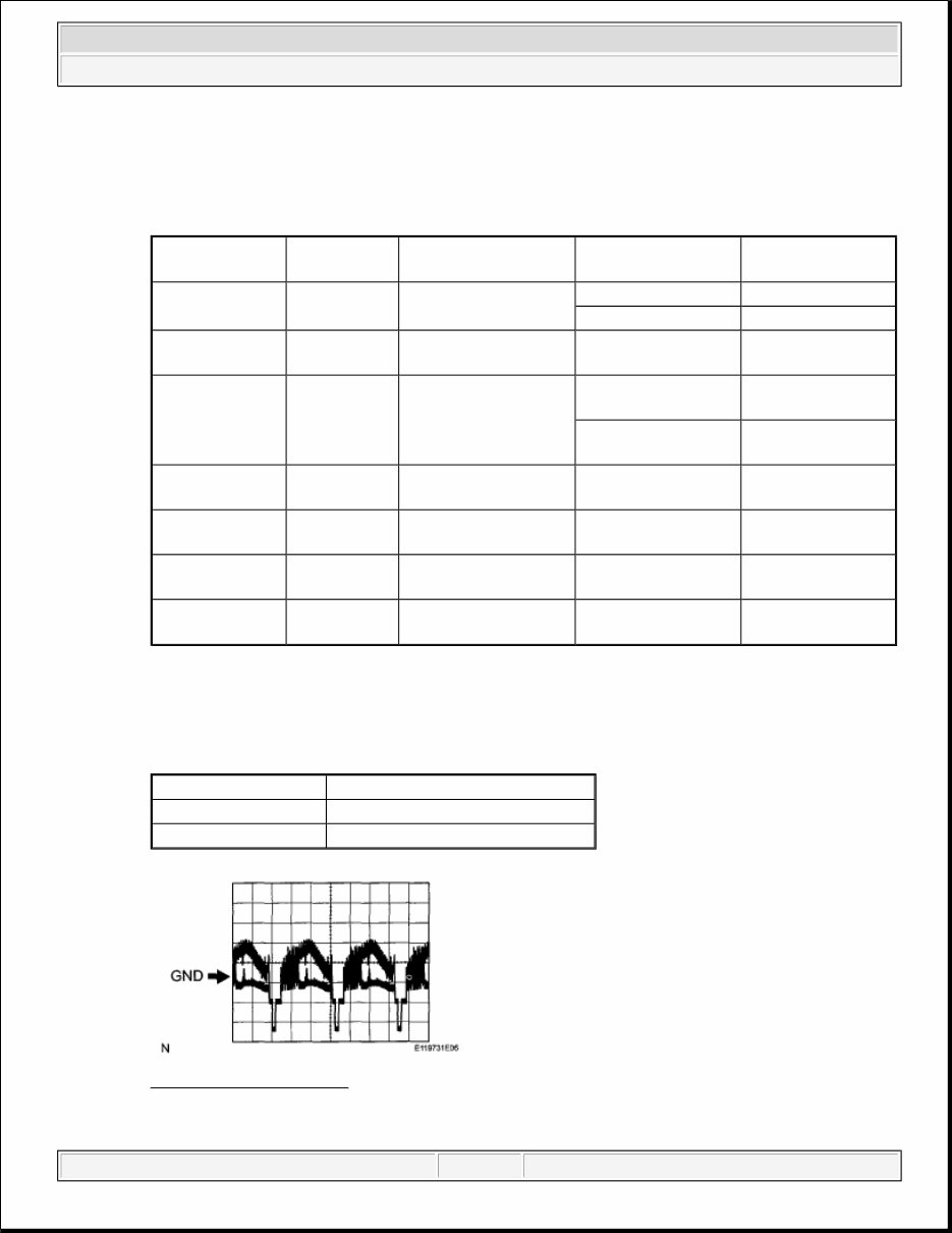
c. Using an oscilloscope, check the waveform.
Waveform (Reference)
WAVEFORM REFERENCE CHART
Fig. 6: Waveform Graph
Courtesy of TOYOTA MOTOR SALES, U.S.A., INC.
Terminal No.
(Symbol)
Wiring Color Terminal Description Condition
Specified
Condition
I8-1 (IG) - I8-2
(E)
LG - W-B Ignition switch signal
Ignition switch off Below 1 V
Ignition switch ON 11 to 14 V
I8-2 (E) - Body
ground
W-B - Body
ground
Ground Always Below 1 V
I8-3 (REV) - I8-
2 (E)
R - W-B Reverse signal
Ignition switch ON,
shift lever not in R
Below 1 V
Ignition switch ON,
shift lever in R
11 to 14 V
I8-6 (CV-) - I8-2
(E)
W - W-B Signal ground Always Below 1 V
I8-7 (CV+) - I8-
2 (E)
R - W-B
Television camera
display signal (Input)
Ignition switch ON,
shift lever in R
Pulse generation
(See c waveform)
I8-13 (CGND)-
Body ground
Shielded -
Body ground
Television camera
ground (Shielded)
Always Below 1 V
I8-14 (CB+) - I8-
2 (E)
B - W-B
Power source to
television camera
Ignition switch ON,
shift lever in R
5.5 to 7.05 V
Terminal Connection I8-7 (CV+) - I8-6 (CV-)
Tester Range 0.2 V/DIV., 50 μS/DIV.
Vehicle Condition Ignition switch ON, shift lever in R
2009 Toyota Tacoma
2009 ACCESSORIES & EQUIPMENT Park Assist / Monitoring - Tacoma
Saturday, September 27, 2014 12:39:08 PM Page 9 © 2011 Mitchell Repair Information Company, LLC.
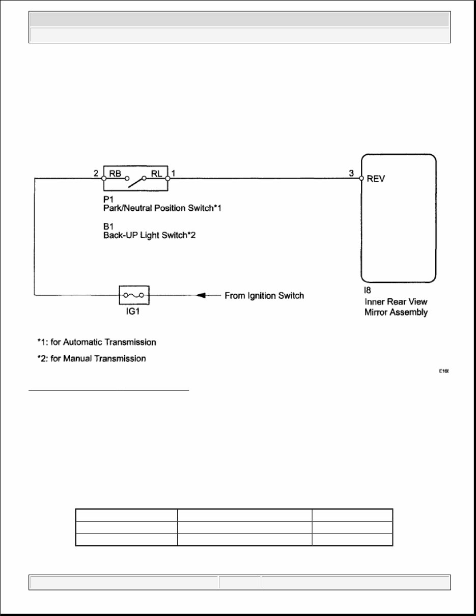
REVERSE SIGNAL CIRCUIT
DESCRIPTION
The inner rear view mirror assembly receives a reverse signal from the park/neutral position switch or the back-
up light switch.
WIRING DIAGRAM
Fig. 7: Reverse Signal - Wiring Diagram
Courtesy of TOYOTA MOTOR SALES, U.S.A., INC.
INSPECTION PROCEDURE
1. INSPECT INNER REAR VIEW MIRROR ASSEMBLY (REVERSE SIGNAL)
a. Disconnect the I8 inner rear view mirror assembly connector.
b. Measure the voltage according to the value(s) in the table below.
Standard Voltage
STANDARD VOLTAGE SPECIFICATION
c. Reconnect the inner rear view mirror assembl y connector.
Tester Connection Switch Condition Specified Condition
I8-3 (REV) - Body ground Ignition switch ON, shift lever In R 11 to 14 V
Ignition switch ON, shift lever In P Below 1 V
2009 Toyota Tacoma
2009 ACCESSORIES & EQUIPMENT Park Assist / Monitoring - Tacoma
Saturday, September 27, 2014 12:39:08 PM Page 10 © 2011 Mitchell Repair Information Company, LLC.
You're Reading a Preview
What's Included?
Lifetime Access
Access Contents & Bookmarks
Print one or all pages of your manual