CL03Y–01 – CLUTCH TROUBLESHOOTING CL–1 1607 AuthorĂ: DateĂ: TROUBLESHOOTING PROBLEM SYMPTOMS TABLE Use the table below to help you find the cause of the problem. The numbers indicate the priority of the likely cause of the problem. Check each part in order. If necessary, replace these parts. Symptom Suspect Area See page Clutch grabs/chatters 1. Engine mounting (Loosen) 2. Clutch disc (Runout is excessive) 3. Clutch disc (Oily) 4. Clutch disc (Worn out) 5. Clutch disc (Damaged torsion rubber) 6. Clutch disc (Glazed) 7. Diaphragm spring (Out of tip alignment) – CL–14 CL–14 CL–14 CL–14 CL–14 CL–19 Clutch pedal spongy 1. Clutch line (Air in line) 2. Master cylinder cup (Damaged) 3. Release cylinder cup (Damaged) – CL–4 CL–9 Clutch noisy 1. Release bearing (Worn, dirty or damaged) 2. Pilot bearing (Worn or damaged) 3. Input shaft bearing (Worn, dirty or damaged) 4. Clutch disc torsion rubber (Damaged) CL–14 CL–14 – CL–14 Clutch slips 1. Clutch pedal (Freeplay out of adjustment) 2. Clutch disc (Oily) 3. Clutch disc (Worn out) 4. Diaphragm spring (Damaged) 5. Pressure plate (Distortion) 6. Flywheel (Distortion) CL–2 CL–14 CL–14 CL–14 CL–14 – Clutch does not disengage 1. Clutch pedal (Freeplay out of adjustment) 2. Clutch line (Air in line) 3. Master cylinder cup (Damaged) 4. Release cylinder cup (Damaged) 5. Input shaft bearing (Worn, dirty or damaged) 6. Pilot bearing (Worn or damaged) 7. Clutch disc (Out of true) 8. Clutch disc (Runout is excessive) 9. Clutch disc (Lining broken) 10. Clutch disc (Dirty or burred) 11. Clutch disc (Oily) 12. Clutch disc (Lack of spline grease) 13. Diaphragm spring (Damaged) 14. Diaphragm spring (Out of tip alignment) 15. Pressure plate (Distortion) CL–2 – CL–4 CL–9 – CL–14 CL–14 CL–14 CL–14 CL–14 CL–14 CL–19 CL–14 CL–19 CL–14
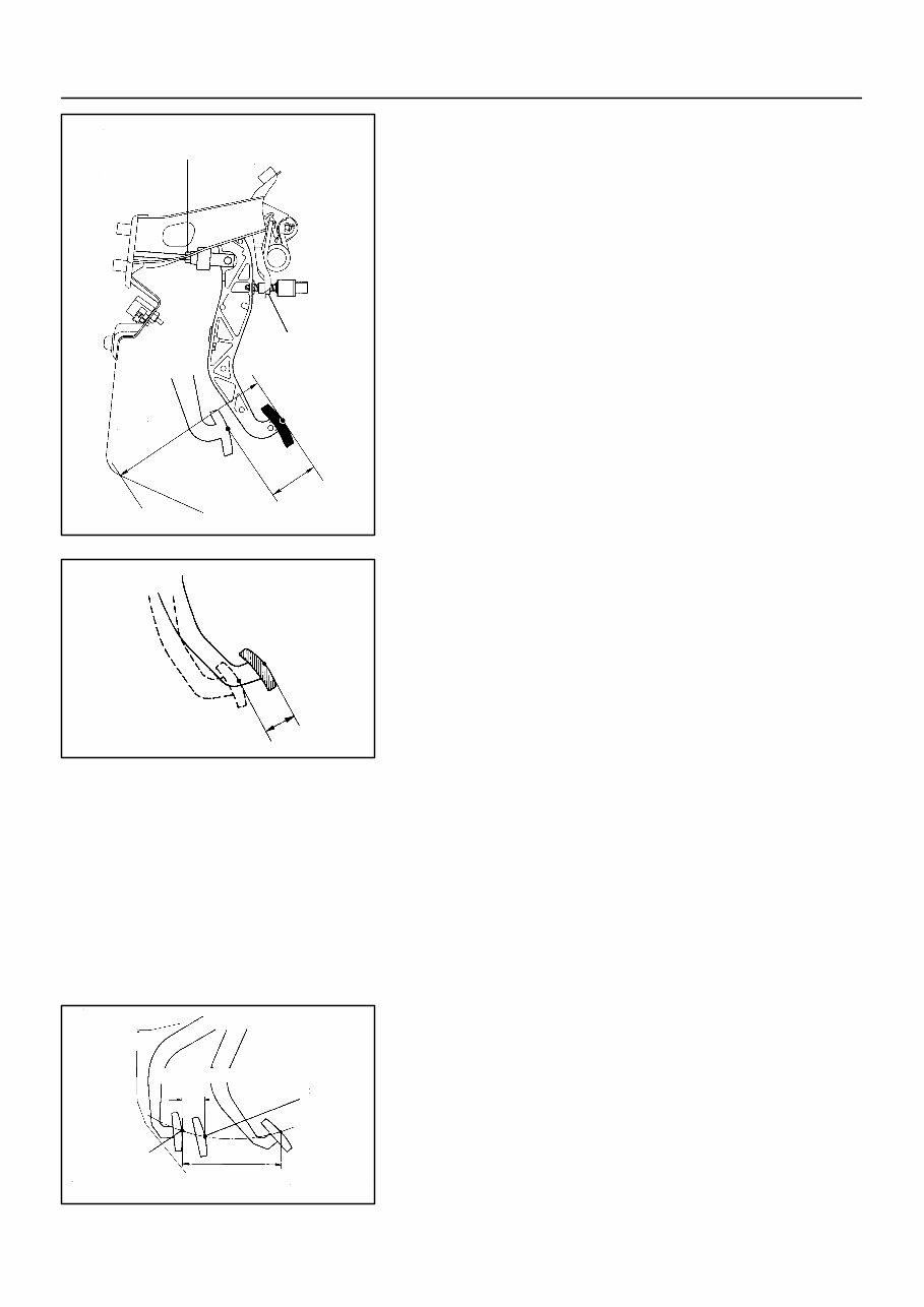
Q04160 Push Rod Play and Freeplay Adjust Point Pedal Height Pedal Height Adjust Point Push Rod Play CL03Z–01 CL0102 Pedal Freeplay Z13785 25 mm (0.98 in.) or more Full Pedal Stroke Full Stroke End Position Release Point CL–2 – CLUTCH CLUTCH PEDAL 1608 AuthorĂ: DateĂ: CLUTCH PEDAL INSPECTION 1. CHECK PEDAL HEIGHT Pedal height from asphalt sheet: 146.2 – 156.2 mm (5.76 – 6.15 in.) 2. IF NECESSARY, ADJUST PEDAL HEIGHT Loosen the lock nut and clutch switch until the height is correct. Tighten the lock nut. HINT: Before rotating the clutch switch for pedal height adjustment, disconnect the clutch switch connector. 3. CHECK PEDAL FREEPLAY AND PUSH ROD PLAY Push in on the pedal until the beginning of clutch resistance is felt. Pedal freeplay: 5.0 – 15.0 mm (0.197 – 0.591 in.) Gently push on the pedal until the resistance begins to increase a little. Push rod play at pedal top: 1.0 – 5.0 mm (0.039 – 0.197 in.) 4. IF NECESSARY, ADJUST PEDAL FREEPLAY AND PUSH ROD PLAY (a) Loosen the lock nut and turn the push rod until the free- play and push rod play are correct. (b) Tighten the lock nut. (c) After adjusting the pedal freeplay, check the pedal height. 5. INSPECT FULL PEDAL STROKE Full pedal stroke: 132.0 – 138.0 mm (5.20 – 5.43 in.) 6. INSPECT CLUTCH RELEASE POINT (a) Pull the parking brake lever and install wheel stopper. (b) Start the engine and idle the engine. (c) Without depressing the clutch pedal, slowly shift the shift lever into the reverse position until the gears contact. (d) Gradually depress the clutch pedal and measure the stroke distance from the point the gear noise stops (re- lease point) up to the full stroke end position.
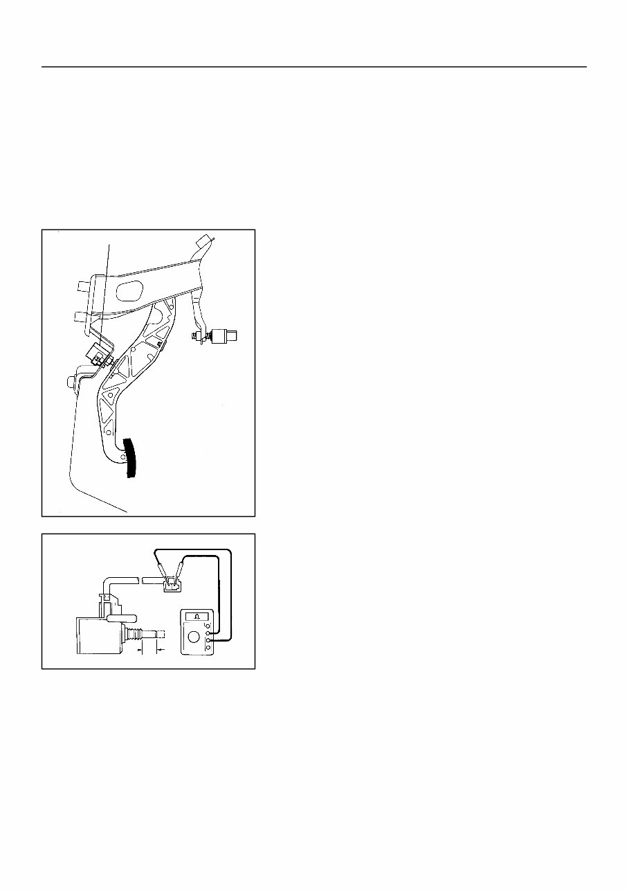
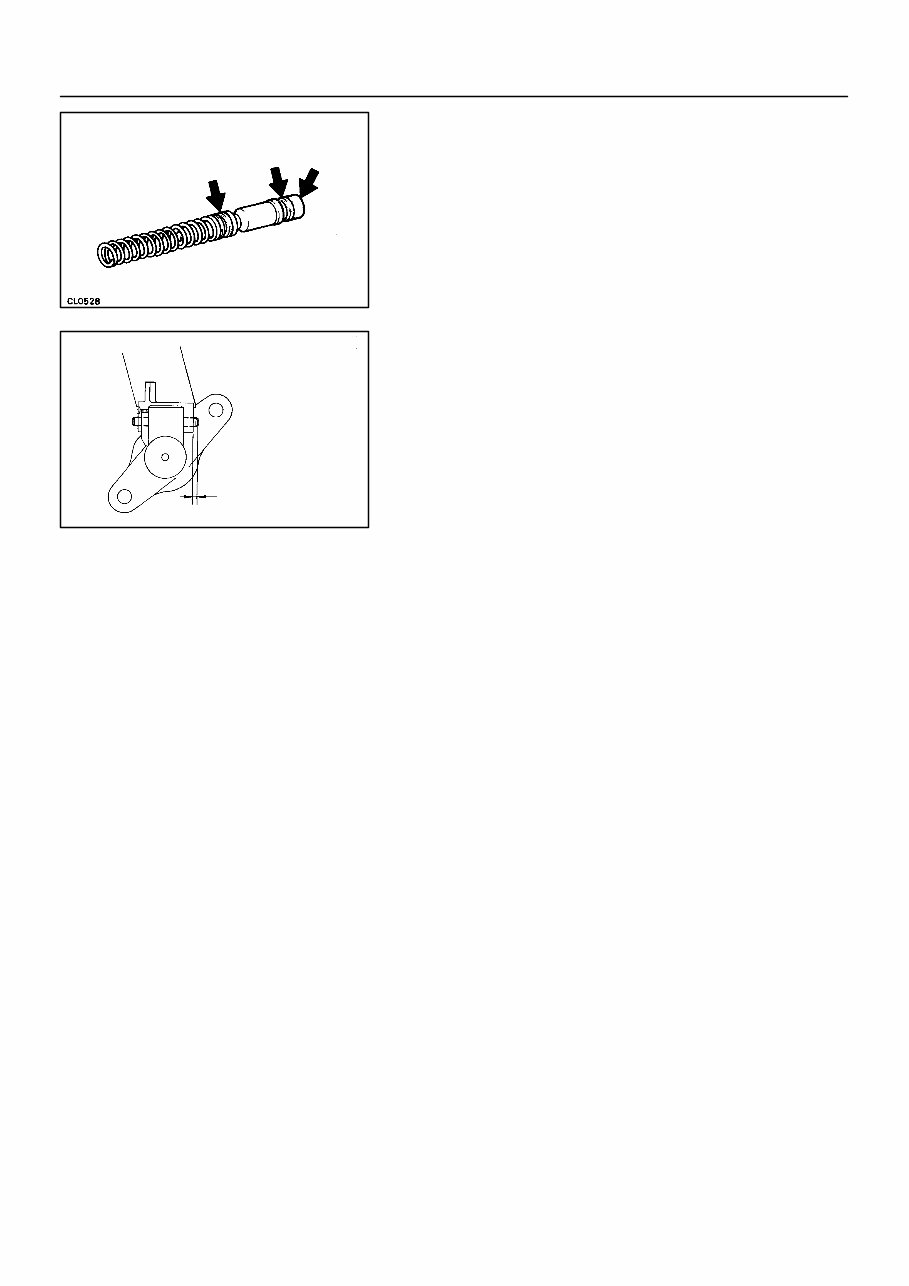
Q04185 Clutch Start Switch Q00617 8 ± 0.5 mm (0.31 ± 0.020 in.) – CLUTCH CLUTCH PEDAL CL–3 1609 AuthorĂ: DateĂ: Standard distance: 25 mm (0.98 in.) or more (From pedal stroke end position to release point) If the distance is not as specified, do the following operation. z Inspect pedal height. z Inspect push rod play and pedal freeplay. z Bleed the clutch line. z Inspect the clutch cover and disc. 7. CHECK CLUTCH START SYSTEM (a) Check that the engine does not start when the clutch ped- al is released. (b) Check that the engine starts when the clutch pedal is fully depressed. If necessary, adjust or replace the clutch start switch. 8. INSPECT CONTINUITY OF CLUTCH START SWITCH (a) Check that there is continuity between the terminals when the switch is ON (pushed). (b) Check that there is no continuity between the terminals when the switch is OFF (free). If continuity is not as specified, replace the switch.
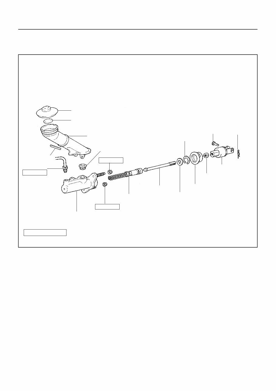
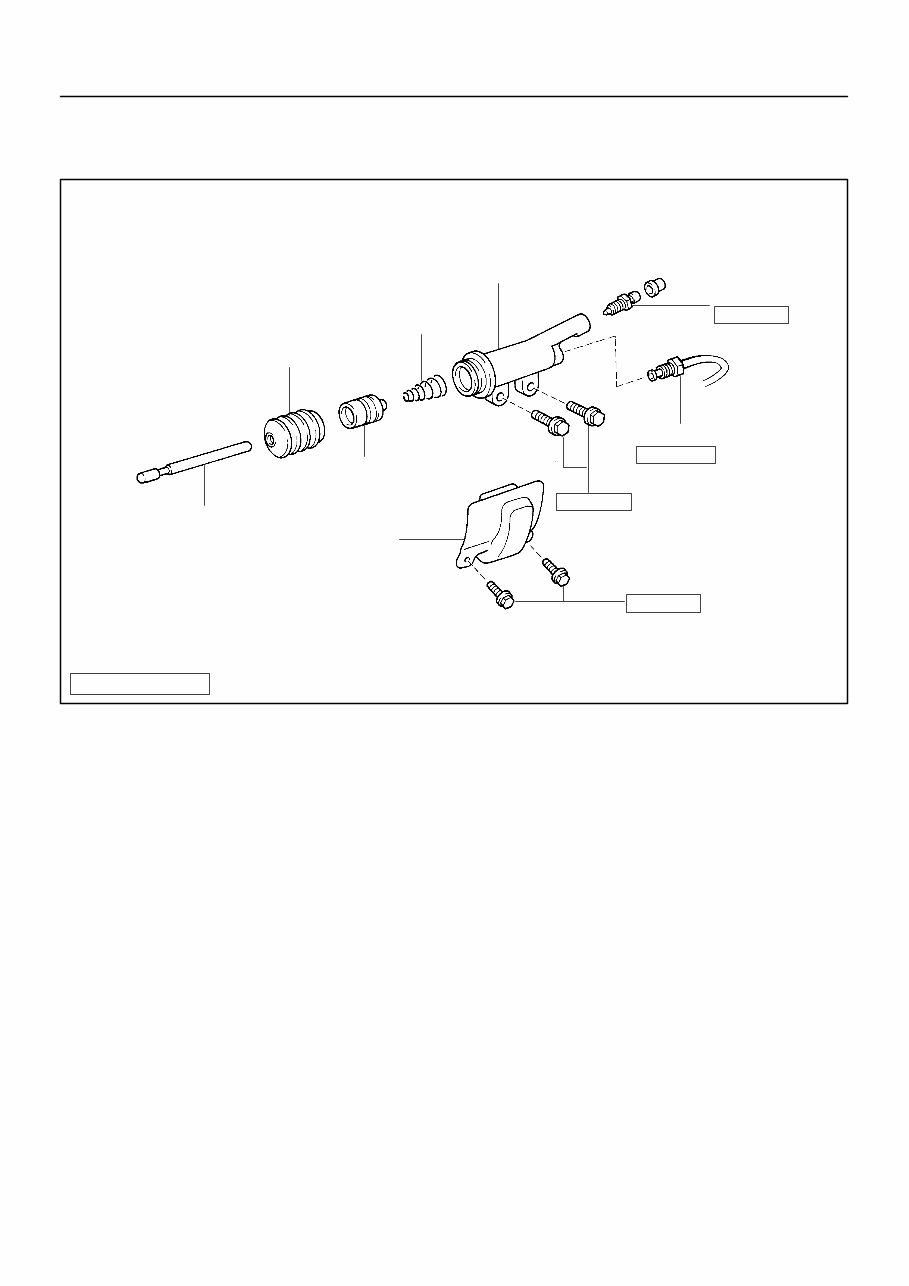
CL040–01 Z16903 Filler Cap Reservoir Tank Slotted Spring Pin Clutch Line Push Rod z Grommet Float Clip Pin Clevis Boot Washer z Snap Ring Lock Nut 15 (155, 11) 12 (125, 9) 12 (125, 9) N·m (kgf·cm, ft·lbf) : Specified torque z Non–reusable part Piston Master Cylinder Body CL–4 – CLUTCH CLUTCH MASTER CYLINDER 1610 AuthorĂ: DateĂ: CLUTCH MASTER CYLINDER COMPONENTS
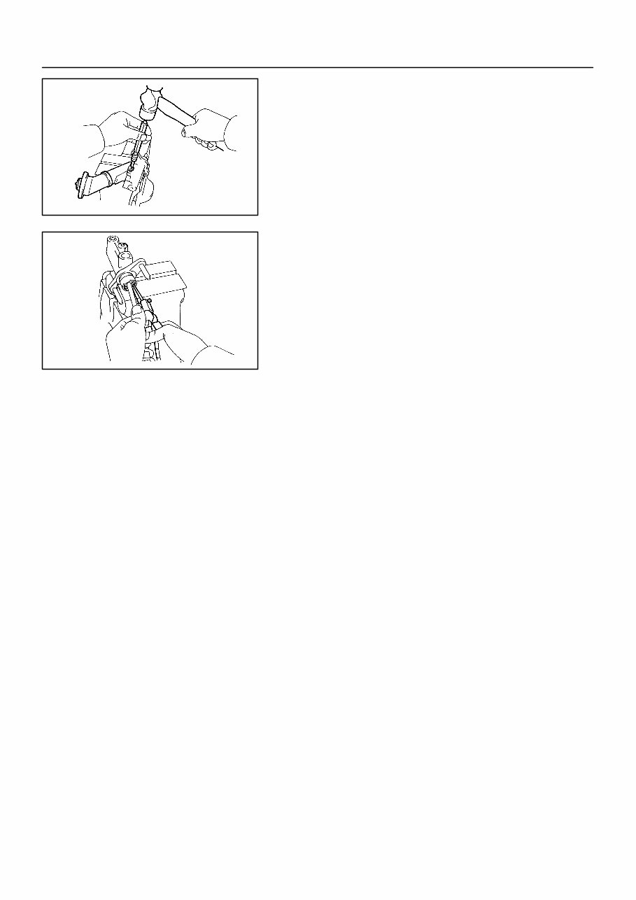
CL041–01 Q04188 SST – CLUTCH CLUTCH MASTER CYLINDER CL–5 REMOVAL 1. DRAIN OUT FLUID WITH SYRINGE 2. DISCONNECT CLUTCH LINE UNION Using SST, disconnect the union nut. SST 09023–00100 Torque: 15 N·m (155 kgf·cm, 11 ft·lbf) 3. REMOVE CLIP AND PIN 4. REMOVE 2 MOUNTING NUTS AND PULL OUT MAS- TER CYLINDER Torque: 12 N·m (125 kgf·cm, 9 ft·lbf)
CL042–01 Q04189 Q04190 CL–6 – CLUTCH CLUTCH MASTER CYLINDER DISASSEMBLY 1. REMOVE RESERVOIR TANK (a) Using a pin punch and hammer, drive out the slotted spring pin. (b) Remove the reservoir tank and grommet. 2. REMOVE PUSH ROD (a) Pull back the boot, and using snap ring pliers, remove the snap ring. (b) Pull out the push rod. 3. REMOVE PISTON
CL044–01 Z08053 Q04313 Protrusion 1.5 – 3.5 mm (0.059 – 0.138 in.) – CLUTCH CLUTCH MASTER CYLINDER CL–7 REASSEMBLY 1. COAT PARTS WITH LITHIUM SOAP BASE GLYCOL GREASE, AS SHOWN 2. INSERT PISTON INTO CYLINDER 3. INSTALL PUSH ROD ASSEMBLY WITH NEW SNAP RING 4. INSTALL RESERVOIR TANK (a) Install the reservoir tank and a new grommet. (b) Using a pin punch and hammer, drive in the slotted spring pin.
CL043–01 CL–8 – CLUTCH CLUTCH MASTER CYLINDER INSTALLATION Installation is in the reverse order of removal. (See page CL–5) HINT: After installation, adjust the clutch pedal and bleed the clutch system.
If you are in need of a repair manual for your 1994 Toyota Supra, look no further. This comprehensive manual is suitable for both professional mechanics and DIY enthusiasts. In the past, traditional paper manuals were the norm, but now you can access all the necessary information in a more convenient digital format.
Whether you are looking to address brake issues, replace suspension components, troubleshoot engine problems, or perform standard maintenance, this manual has you covered. It contains detailed service information for brakes, engine, suspension, steering, drivetrain, electrical systems, heating, air conditioning, and more.
By utilizing this repair manual, you can save a significant amount of money on vehicle maintenance and repairs. Mechanics often charge high fees for their services, making a DIY approach a cost-effective alternative. The manual is compatible with Windows, Mac computers, smartphones, and tablets, ensuring easy access for all users.