2011-2013 Toyota Highlander Service & Repair Manual
What's Included?
Lifetime Access
Fast Download Speeds
Online & Offline Access
Access PDF Contents & Bookmarks
Full Search Facility
Print one or all pages of your manual
2011-2013 Toyota Highlander
ACCESSORIES & EQUIPMENT Audio Entertainment System (Diagnostic Codes & Symptom Tests) (Except Hybrid) - Highlander AUDIO AND VISUAL SYSTEM DTC 01-21: ROM ERROR; DTC 01-22: RAM ERROR; DTC 01-2E: EEPROM ERROR DESCRIPTION INSPECTION PROCEDURE HINT: After the inspection is completed, clear the DTCs. PROCEDURE 1. REPLACE RADIO RECEIVER ASSEMBLY a. Replace the radio receiver assembly. Refer to REMOVAL . NEXT --> END DTC 01-D5: ABSENCE OF REGISTRATION UNIT; DTC 01-D8: NO RESPONSE FOR CONNECTION CHECK; DTC 01-D9: LAST MODE ERROR; DTC 01-DA: NO RESPONSE AGAINST ON / OFF COMMAND; DTC 01-DB: MODE STATUS ERROR; DTC 01-DE: SLAVE RESET DESCRIPTION DTC No. DTC Detection Condition Trouble Area 01-21 A ROM malfunction exists. Radio receiver assembly 01-22 A RAM malfunction exists. 01-2E A checksum malfunction exists. DTC No. DTC Detection Condition Trouble Area 01-D5 *1, *3 A device indicated by the sub-code is (was) disconnected from the system with the ignition switch to ON or ACC. The communication condition with the device that the DTC shows cannot be obtained when the engine was started. Power source circuit of the component shown by the sub-code 01-D8 *2, *3 The device indicated by the sub-code is (was) disconnected from the system after the engine starts. The device that had functioned before the
HINT: *1: Even if no fault is present, this DTC may be stored depending on the battery condition or engine start voltage. *2: If the power connector is disconnected after the engine starts, this DTC is stored after 180 seconds. *3: If the device is reported as not existing during verification, check the power source circuit and AVC- LAN circuit for the device. INSPECTION PROCEDURE PROCEDURE 1. CHECK "RADIO RECEIVER COMMUNICATION ERROR" IN PROBLEM SYMPTOMS TABLE HINT: Refer to Radio Receiver Communication Error. Refer to Radio Receiver Communication Error . NEXT --> END DTC 01-D6: NO MASTER; DTC 01-D7: CONNECTION CHECK ERROR DESCRIPTION 01-D9 *1, *3 engine stopped is (was) disconnected from the system with the ignition switch to ON or ACC. AVC-LAN circuit between the radio receiver assembly and component shown by the sub-code Component shown by the sub-code 01-DA *3 No response is identified when changing mode. Sound and image do not change by switch operation. 01-DB *1, *3 A dual alarm is detected. 01-DE *3 A slave device has been disconnected after the engine starts. NOTE: Before starting troubleshooting, be sure to clear the DTCs stored due to the reasons described in the HINT above. Then, check for DTCs and troubleshoot according to the output DTCs. The radio receiver assembly is the master unit. Be sure to clear and recheck for DTCs after the inspection is completed to confirm that no DTCs are output. NOTE: Be sure to read Description before performing the following procedure.
HINT: *1: Even if no fault is present, this DTC may be stored depending on the battery condition or engine start voltage. *2: When 210 seconds have elapsed after disconnecting the power supply connector of the master component with the ignition switch to ON or ACC, this DTC is stored. INSPECTION PROCEDURE PROCEDURE 1. CHECK RADIO RECEIVER ASSEMBLY POWER SOURCE CIRCUIT HINT: Refer to Radio Receiver Power Source Circuit. Refer to Radio Receiver Power Source Circuit . If the power source circuit is operating normally, proceed to the next step. DTC No. DTC Detection Condition Trouble Area 01-D6*1 Either condition is met: The device that stores (stored) the DTC has (had) been disconnected with the ignition switch to ON or ACC. The master device has (had) been disconnected when this DTC is (was) stored. Radio receiver assembly power source circuit Power source circuit of the component which has stored this code AVC-LAN circuit between the radio receiver assembly and component which has stored this code Component which has stored this code Radio receiver assembly 01-D7*2 Either condition is met: The device that stored the code has (had) been disconnected after the engine starts (started). The master device has (had) been disconnected when this DTC is (was) stored. NOTE: Before starting troubleshooting, be sure to clear the DTCs stored due to the reasons described in the HINT above. Then, check for DTCs and troubleshoot according to the output DTCs. The radio receiver assembly is the master unit. Be sure to clear and recheck for DTCs after the inspection is completed to confirm that no DTCs are output. NOTE: Be sure to read Description before performing the following procedure.
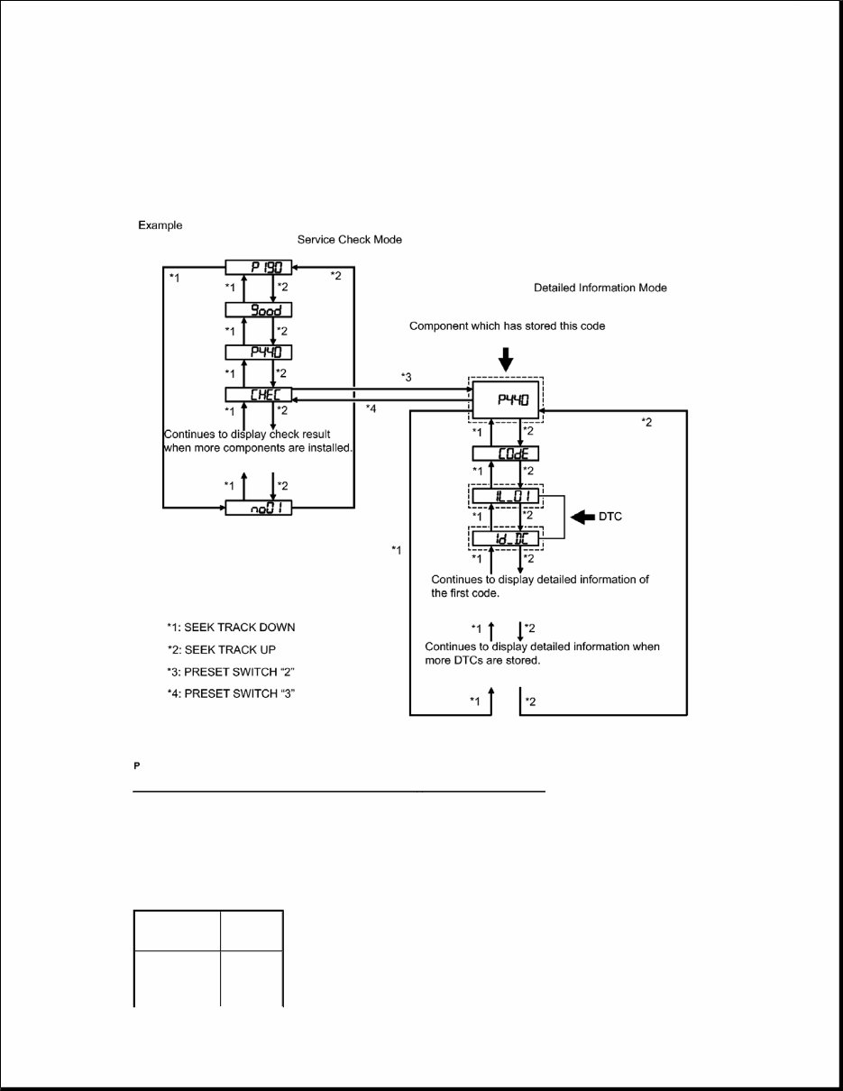
NEXT: Go to next step 2. IDENTIFY COMPONENT WHICH HAS STORED THIS CODE a. Enter diagnostic mode. Fig. 1: Service Check Mode Flow Chart - Diagnostic Mode Courtesy of TOYOTA MOTOR SALES, U.S.A., INC. b. Press preset switch "2" to change the mode to "Detailed Information Mode". c. Identify the component which has stored this code. COMPONENT TABLE Component Physical Address Stereo component 440
HINT: The physical address "P440" shown in the above example indicates the stereo component amplifier assembly. For details of the DTC display, refer to DTC Check/Clear. Refer to DTC CHECK / CLEAR . NEXT: Go to next step 3. CHECK COMPONENT SHOWN BY SUB-CODE a. Select the component shown by the sub-code. HINT: The satellite radio tuner is built into the radio receiver assembly. If there is a problem between the satellite radio tuner and radio receiver assembly, replace the radio receiver assembly. COMPONENT TABLE B --> See step 10 A: Go to next step 4. CHECK POWER SOURCE CIRCUIT OF COMPONENT WHICH HAS STORED THIS CODE a. Inspect the power source circuit of the component which has stored this code. If the power source circuit is operating normally, proceed to the next step. COMPONENT TABLE amplifier assembly Multi-media interface ECU 388 Satellite radio tuner 1F1 Component Proceed to Except satellite radio tuner A Satellite radio tuner (1F1) B
NEXT: Go to next step 5. INSPECT RADIO RECEIVER ASSEMBLY a. Disconnect the radio receiver assembly connectors. Component Proceed to Stereo component amplifier assembly Stereo component amplifier power source circuit. Refer to Stereo Component Amplifier Power Source Circuit Multi-media interface ECU Multi-media interface ECU power source circuit. Refer to Multi - media Interface ECU Power Source Circuit
Fig. 2: Measuring Resistance Of Radio Receiver Assembly Courtesy of TOYOTA MOTOR SALES, U.S.A., INC. b. Measure the resistance according to the value(s) in the table below.
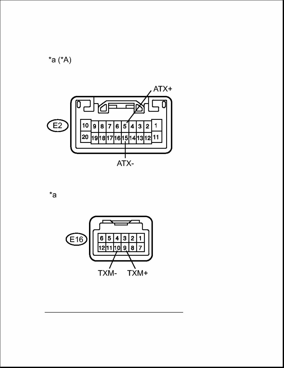
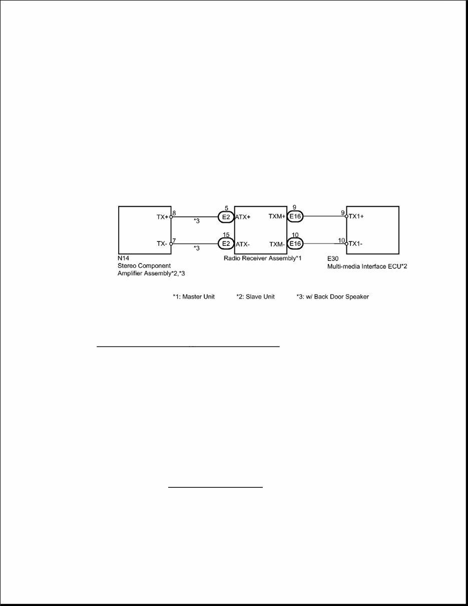
Standard Resistance W/ BACK DOOR SPEAKER W/O BACK DOOR SPEAKER TEXT IN ILLUSTRATION NG --> See step 10 OK: Go to next step 6. CHECK HARNESS AND CONNECTOR HINT: For details of the connectors, refer to Terminals of ECU. Refer to TERMINALS OF ECU . a. Referring to the following AVC-LAN wiring diagram, check the AVC-LAN circuit between the radio receiver assembly and component which has stored this code. Tester Connection Condition Specified Condition E2-5 (ATX+) - E2-15 (ATX-) Always 60 to 80 ohms E16-9 (TXM+) - E16-10 (TXM-) Always 60 to 80 ohms Tester Connection Condition Specified Condition E16-9 (TXM+) - E16-10 (TXM-) Always 60 to 80 ohms *A w/ Back Door Speaker *a Component without harness connected (Radio Receiver Assembly)
1. Disconnect all connectors between the radio receiver assembly and component which has stored this code. 2. Check for an open or short in the AVC-LAN circuit between the radio receiver assembly and component which has stored this code. OK There is no open or short circuit. Fig. 3: Identifying AVC - LAN Wiring Diagram Courtesy of TOYOTA MOTOR SALES, U.S.A., INC. NG --> REPAIR OR REPLACE HARNESS OR CONNECTOR OK: Go to next step 7. REPLACE COMPONENT WHICH HAS STORED THIS CODE a. Replace the component which has stored this code with a known good one. NEXT: Go to next step 8. CLEAR DTC a. Clear the DTCs. Refer to DTC CHECK / CLEAR . NEXT: Go to next step 9. RECHECK FOR DTC a. Recheck for DTCs and check if the same DTC is output again.
Get your hands on the 2011-2013 Toyota Highlander Service & Repair Manual, a comprehensive guide for fixing truck problems. Whether you're a professional mechanic or a DIY enthusiast, this manual equips you with the manufacturer's recommended troubleshooting charts and replacement procedures. It includes step-by-step instructions, clear images, and exploded-view illustrations to assist you in maintaining your vehicle's durability.
Regular maintenance is crucial for your truck, and this manual provides the necessary resources to address wear and tear on various parts. Say goodbye to flipping through countless pages or dealing with greasy, torn, or lost pages. This .pdf format manual allows for easy accessibility, searchability, and portability on electronic devices such as PCs, Mac computers, smartphones, and tablets. If you prefer a physical copy, you can also print it out. The manual is available in English and requires Adobe Reader (free) for access.
Recently Viewed
5,521,897Happy Clients
2,594,462eManuals
1,120,453Trusted Sellers
15Years in Business
Price:
Actual Price:
2011-2013 Toyota Highlander Service & Repair Manual