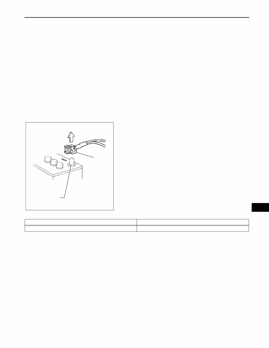
A750E AUTOMATIC TRANSMISSION – AUTOMATIC TRANSMISSION SYSTEM AT–1 AT AUTOMATIC TRANSMISSION SYSTEM PRECAUTION 1. PRECAUTION NOTICE: • Perform the RESET MEMORY (AT initialization) when replacing the automatic transmission assembly, engine assembly or ECM (See page AT- 19). • Perform the REGISTRATION (VIN registration) when replacing the ECM (See page ES-15). HINT: RESET MEMORY cannot be completed by only disconnecting the negative cable from the battery. 2. DISCONNECT AND RECONNECT CABLE OF NEGATIVE BATTERY TERMINAL (a) Before performing electronic work, disconnect the cable from the negative (-) battery terminal in order to prevent it from shorting and burning out. (b) Before disconnecting and reconnecting the battery cable, turn the ignition switch OFF and the headlight dimmer switch OFF. Then loosen the terminal nut completely. Do not damage the cable or terminal. (c) When the battery cable is disconnected, the clock and radio settings and stored DTCs are erased. Therefore, before disconnecting the battery cable, make a notes of them. NOTICE: When the cable is disconnected from the negative (-) battery terminal, initialize the following system(s) after the cable is reconnected. 3. CONNECT BATTERY NEGATIVE TERMINAL (a) Connect the battery negative terminal to the cable and run the engine at no less than 2,000 rpm for 2 minutes. NOTICE: If the engine exceeds 2,000 rpm, the A/C magnet clutch is automatically disengaged by the compressor protection control system. 4. PRECAUTION FOR DISASSEMBLY AND REASSEMBLY CAUTION: When using compressed air, always aim away from yourself to prevent Automatic Transmission Fluid (ATF) or kerosene from spraying on your face. Negative (-) Battery Terminal Cable D033496E01 System Name See Procedure Meter / Gauge system ME-10 www.internercarmanuals.co.uk
AT–2 A750E AUTOMATIC TRANSMISSION – AUTOMATIC TRANSMISSION SYSTEM AT NOTICE: • The automatic transmission is composed of precision-made parts, necessitating careful inspection before reassembly because even a small nick could cause fluid leakage or affect performance. • The procedures are organized so that you work on only one component group at a time. This will help avoid confusion with similar-looking parts of different sub-assemblies being on your workbench at the same time. • The component groups are inspected and repaired from the converter housing side. • Whenever possible, complete the inspection, repair and reassembly before proceeding to the next component group. If a defect is found in a certain component group during reassembly, inspect and repair this group immediately. If a component group cannot be assembled because parts are being ordered, be sure to keep all parts of the group in a separate container while proceeding with disassembly, inspection, repair and reassembly of other component groups. • When changing the automatic transmission fluid, use only "Toyota Genuine ATF WS" (ATF JWS3324 or NWS9638). • All disassembled parts should be washed clean, and compressed air should be blown through any fluid passages and holes. • Dry all parts with compressed air. Never use cloth. • The recommended ATF or kerosene should be used for cleaning. • After cleaning, the parts should be arranged in the order they were removed for efficient inspection, repairs, and reassembly. • When disassembling a valve body, be sure to match each valve with its corresponding spring. • New discs for the brakes and clutches that will be used for replacement must be soaked in ATF for at least 15 minutes before reassembly. • All oil seal rings, clutch discs, clutch plates, rotating parts, and sliding surfaces should be coated with ATF prior to reassembly. • All old gaskets and rubber O-rings must be replaced. • Do not apply adhesive cement to gaskets and similar parts. • Make sure that the ends of the snap rings are not aligned with any cutouts. Also make sure that snap rings are correctly installed into the grooves. • If a worn bushing is to be replaced, the sub- assembly containing the bushing must also be replaced. www.internercarmanuals.co.uk
A750E AUTOMATIC TRANSMISSION – AUTOMATIC TRANSMISSION SYSTEM AT–3 AT • Check the thrust bearings and races for wear or damage. Replace if necessary. • Use petroleum jelly to keep parts in place. • When working with FIPG material, perform the following: Using a razor blade and gasket scraper, remove all old FIPG material from the gasket surface. Clean all components thoroughly to remove all foreign matter. Clean both sealing surfaces with a non-residue solvent. Apply FIPG material in a continuous line approximately 1 mm (0.04 in.) in diameter on the sealing surface. Reassemble parts within 10 minutes of applying FIPG material. Failing to do so will require the FIPG material to be removed and reapplied. www.internercarmanuals.co.uk
AT–4 A750E AUTOMATIC TRANSMISSION – AUTOMATIC TRANSMISSION SYSTEM AT DEFINITION OF TERMS Term Definition Monitor description Description of what the ECM monitors and how it detects malfunctions (monitoring purpose and its details). Related DTCs A group of diagnostic trouble codes that are output by the ECM based on the same malfunction detection logic. Typical enabling conditions Preconditions that allow the ECM to detect malfunctions. With all preconditions satisfied, the ECM sets the DTC when the monitored value(s) exceeds the malfunction threshold(s). Sequence of operation The priority order that is applied to monitoring, if multiple sensors and components are used to detect the malfunction. While one sensor is being monitored, the next sensor or component will not be monitored until the previous monitoring has been completed. Required sensor/components The sensors and components that are used by the ECM to detect malfunctions. Frequency of operation The number of times that the ECM checks for malfunctions per driving cycle. "Once per driving cycle" means that the ECM detects the malfunction only one time during a single driving cycle. "Continuous" means that the ECM detects the malfunction every time the enabling conditions are met. Duration The minimum time that the ECM must detect a continuous deviation in the monitored value(s) before setting a DTC. This timing begins after the "typical enabling conditions" are met. Malfunction thresholds Beyond this value, the ECM determines that there is a malfunction and sets a DTC. MIL operation MIL illumination timing after a defect is detected. "Immediate" means that the ECM illuminates the MIL the instant the ECM determines that there is a malfunction. "2 driving cycles" means that the ECM illuminates the MIL if the same malfunction is detected again in a 2nd driving cycle. Component operating range Normal operation range of sensors and solenoids under normal driving conditions. These ranges are for a reference. They cannot be used to determine whether a sensor or solenoid is defective or not. www.internercarmanuals.co.uk
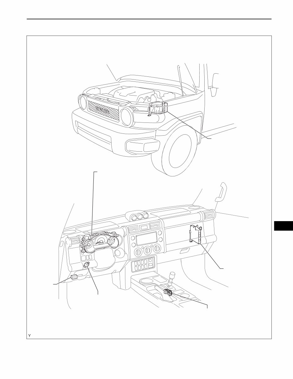
A750E AUTOMATIC TRANSMISSION – AUTOMATIC TRANSMISSION SYSTEM AT–5 AT PARTS LOCATION SHIFT LOCK CONTROL UNIT ASSEMBLY STOP LIGHT SWITCH COMBINATION METER - MIL - ATF TEMPERATURE WARNING LIGHT (TRANSMISSION CONTROL SWITCH) DLC3 ECM NO. 2 ENGINE ROOM RELAY BLOCK - EFI FUSE - ETCS FUSE C130121E01 www.internercarmanuals.co.uk
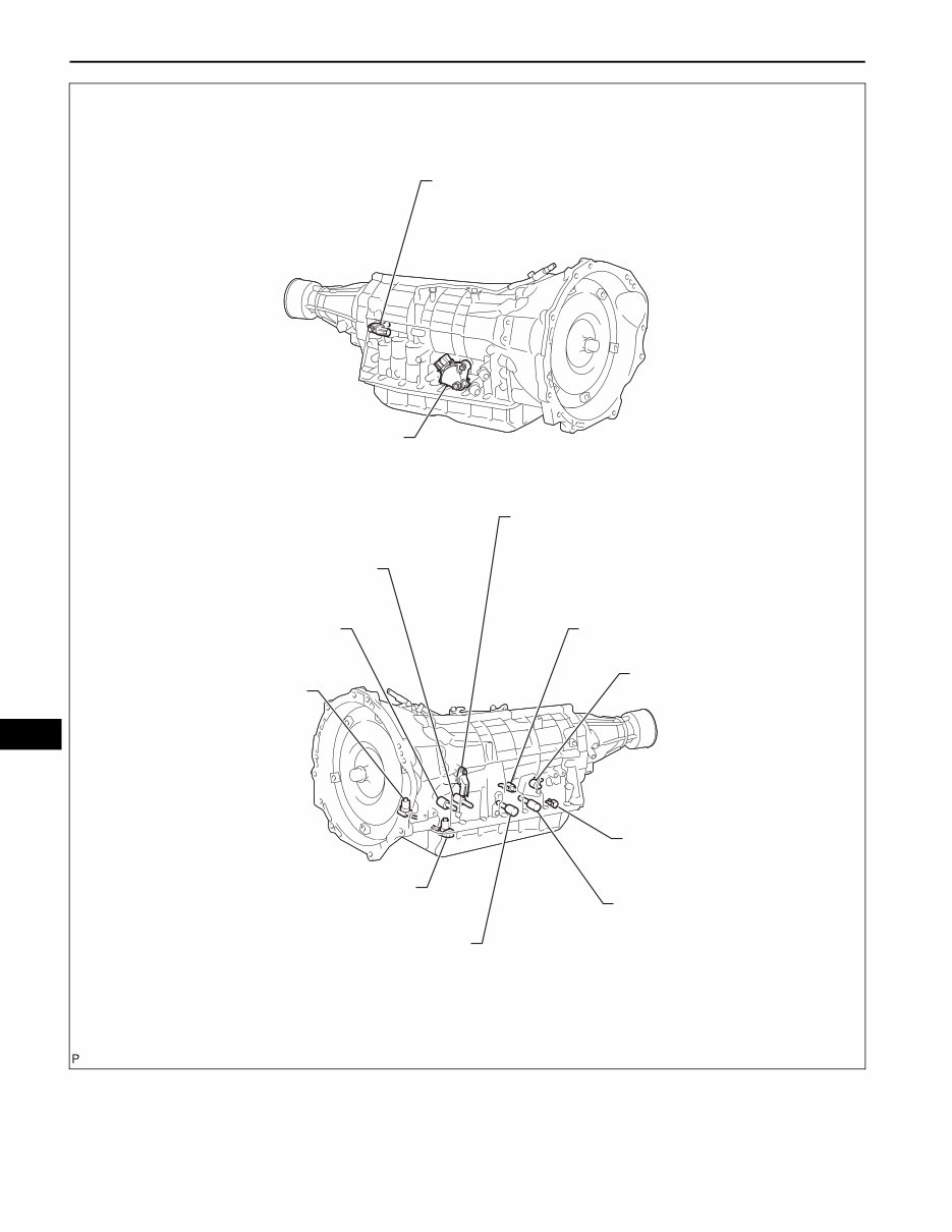
AT–6 A750E AUTOMATIC TRANSMISSION – AUTOMATIC TRANSMISSION SYSTEM AT PARK / NEUTRAL POSITION SWITCH OUTPUT SPEED SENSOR SP2 INPUT SPEED SENSOR NT SHIFT SOLENOID VALVE SL1 SHIFT SOLENOID VALVE SR SHIFT SOLENOID VALVE S1 SHIFT SOLENOID VALVE S2 SHIFT SOLENOID VALVE SL2 SHIFT SOLENOID VALVE SLT SHIFT SOLENOID VALVE SLU NO. 1 ATF TEMPERATURE SENSOR NO. 2 ATF TEMPERATURE SENSOR (TRANSMISSION REVOLUTION SENSOR NT) (TRANSMISSION REVOLUTION SENSOR SP2) C130130E02 www.internercarmanuals.co.uk
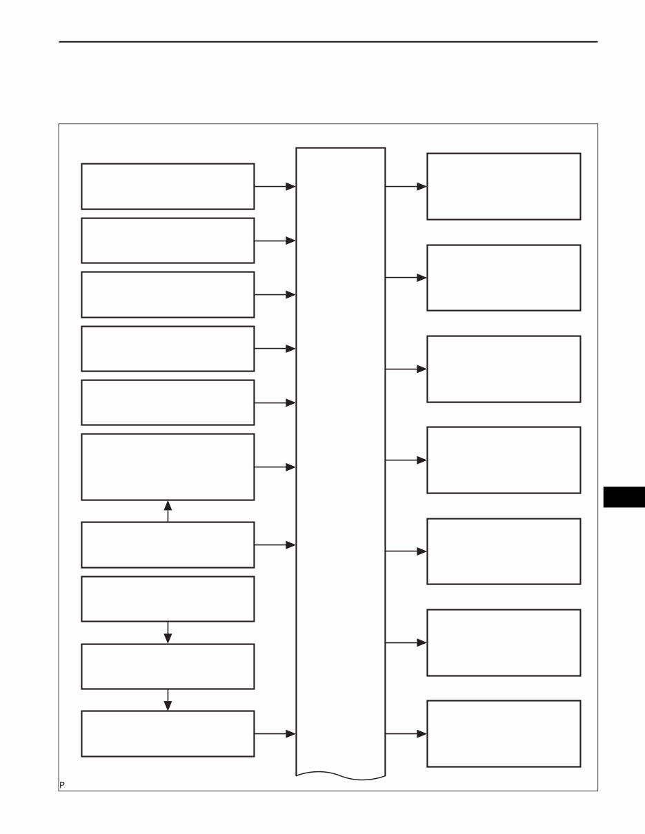
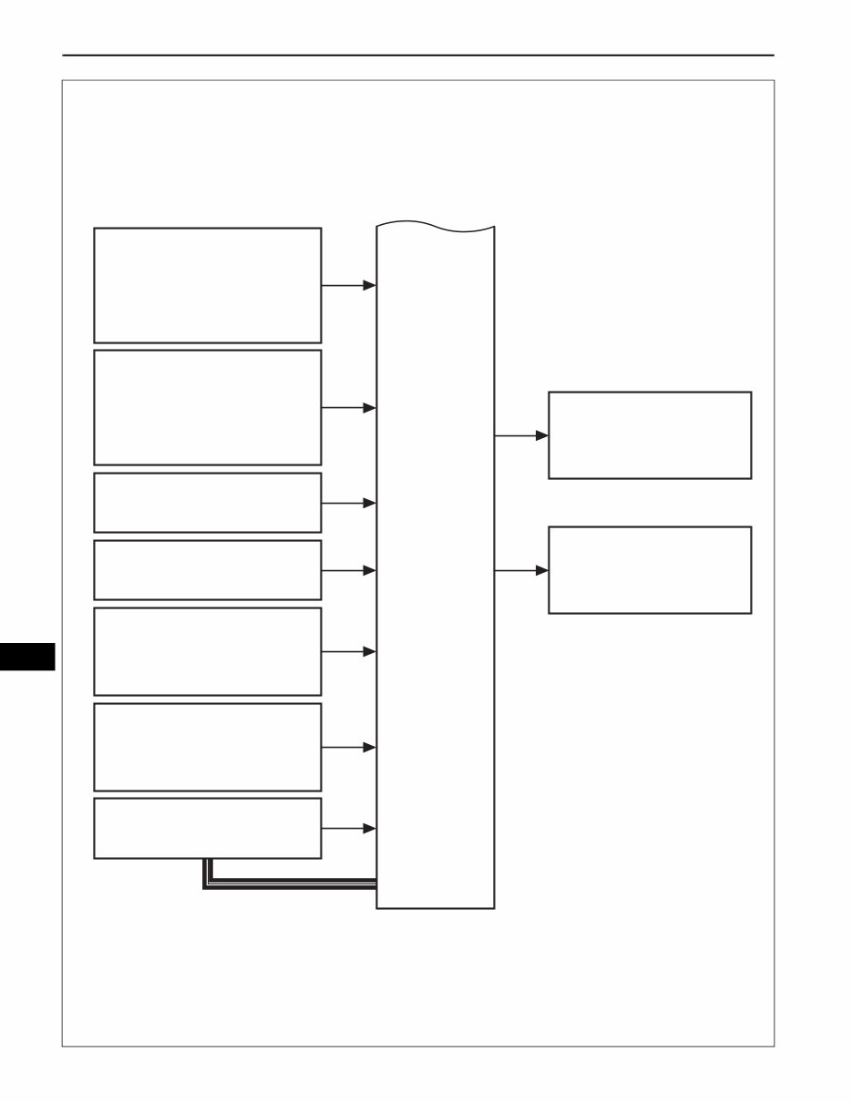
A750E AUTOMATIC TRANSMISSION – AUTOMATIC TRANSMISSION SYSTEM AT–7 AT SYSTEM DIAGRAM The configuration of the electronic control system in the A750E automatic transmission is as shown in the following chart. Mass Air Flow Meter Crankshaft Position Sensor Shift Solenoid Valve SLU Shift Solenoid Valve SLT Shift Solenoid Valve SL2 Shift Solenoid Valve SL1 Shift Solenoid Valve SR Shift Solenoid Valve S2 Shift Solenoid Valve S1 Throttle Position Sensor Accelerator Pedal Position Sensor Park/Neutral Position Switch Speed Sensor Skid Control ECU Combination Meter R, D, 3, 2 SLU SLT SL2 SL1 SR S1 S2 VPA VTA1, 2 VC VPA2 NE Ignition Switch IGSW Shift Lock Control ECU 4, L VG ECM NSW SPD (Transmission Control Switch) A107745E04 www.internercarmanuals.co.uk
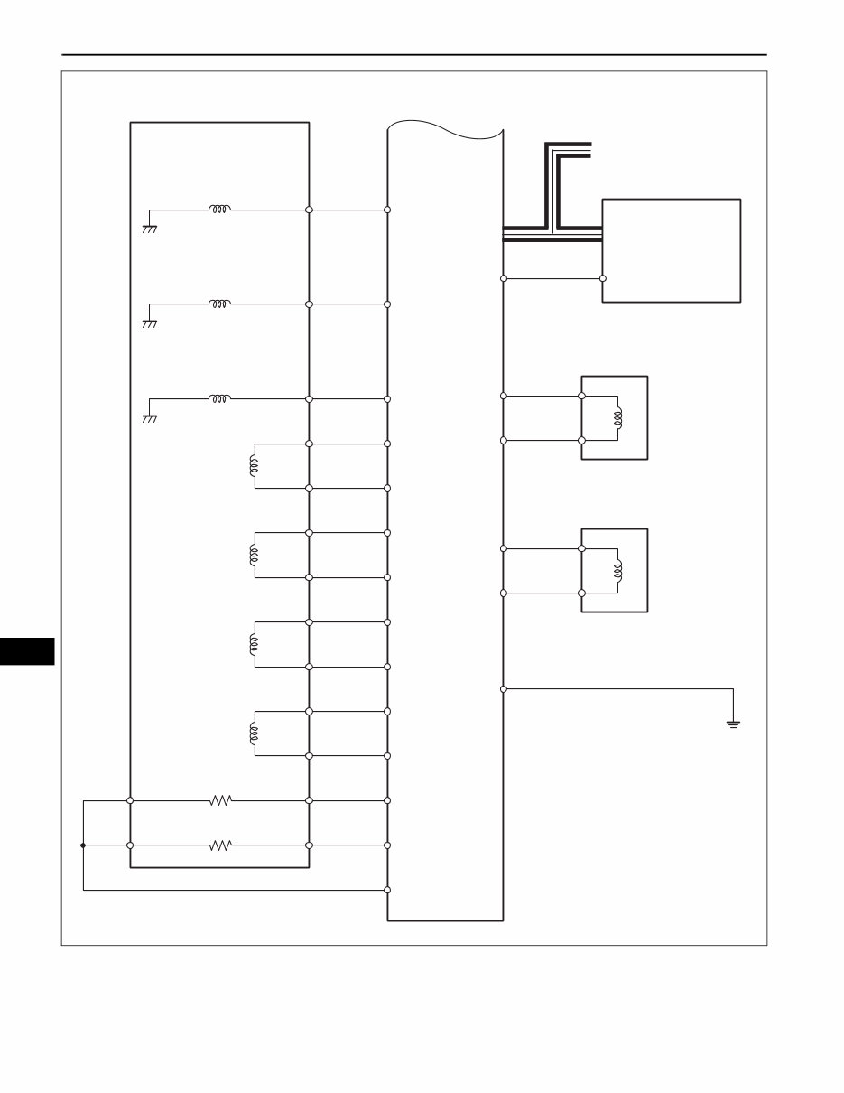
AT–8 A750E AUTOMATIC TRANSMISSION – AUTOMATIC TRANSMISSION SYSTEM AT Input Speed Sensor NT Output Speed Sensor SP2 No. 1 ATF Temperature Sensor No. 2 ATF Temperature Sensor Stop Light Switch DLC3 Engine Coolant Temperature (ECT) Sensor NT SP2 THO1 THO2 ECM W OILW STP THW TC CAN MIL (Malfunction Indicator Lamp) ATF Temperature Warning Light (Transmission Revolution Sensor NT) (Transmission Revolution Sensor SP2) A111865E02 www.internercarmanuals.co.uk
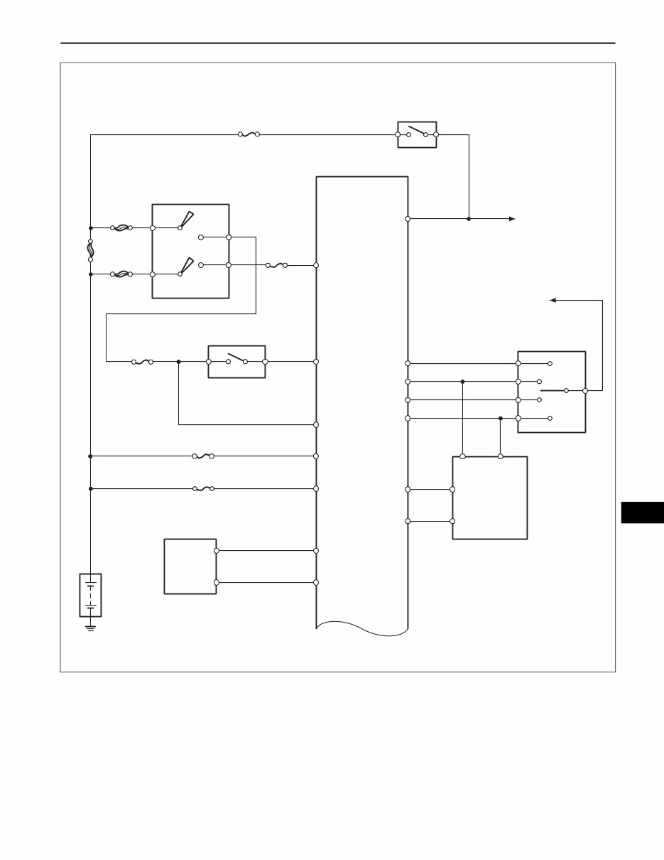
A750E AUTOMATIC TRANSMISSION – AUTOMATIC TRANSMISSION SYSTEM AT–9 AT AM1 AM2 AM1 AM2 ALT ST1 IG2 IGN ETCS EFI To IG1 Fuse To STOP LP CTRL Relay Shift Lock Control ECU STOP Stop Light Switch ECM IGSW STA STA NSW BATT SPD OILW L 4 2 3 D R LL 2L DL RL RB STP MT4 NSSD NSSL MTL Combination Meter B L Park/Neutral Position Switch Park/Neutral Position Switch +BM (Transmission Control Switch) Battery C130132E01 www.internercarmanuals.co.uk
If you are in need of a repair manual for your 2007 Toyota FJ Cruiser, look no further. This comprehensive manual is suitable for both professional mechanics and DIY enthusiasts. In the past, traditional paper manuals were the norm, but now you can access all the necessary information in a more convenient digital format.
Whether you are looking to address brake issues, replace suspension components, troubleshoot engine problems, or perform standard maintenance, this manual has got you covered. It contains detailed service information for various vehicle systems including brakes, engine, suspension, steering, drivetrain, electrical, heating, and air conditioning.
By utilizing this repair manual, you can save a significant amount of money on vehicle maintenance and repairs. Professional mechanic services can be costly, making a DIY approach with the aid of this manual a cost-effective alternative. The manual is compatible with Windows, Mac computers, smartphones, and tablets, ensuring ease of access for all users.