

2009 Toyota Camry Service & Repair Manual
What's Included?
Fast Download Speeds
Offline Viewing
Access Contents & Bookmarks
Full Search Facility
Print one or all pages of your manual
FOREWORD
This repair manual has been prepared to provide essential in-
formation on body panel repair methods (including cutting and
welding operations, but excluding painting) for the TOYOTA
CAMRY.
Applicable models: ACV 40 series
GSV 40 series
This manual consists of body repair methods, exploded dia-
grams and illustrations of the body components and other in-
formation relating to body panel replacement such as handling
precautions, etc. However, it should be noted that the front fend-
ers of this TOYOTA model are bolted on and require no welding.
When repairing, don’t cut and join areas that are not shown in
this manual. Only work on the specified contents to maintain
body strength.
Body construction will sometimes differ depending on specifica-
tions and country of destination. Therefore, please keep in mind
that the information contained herein is based on vehicles for
general destinations.
For the repair procedures and specifications other than collision-
damaged body components of the TOYOTA CAMRY refer to the
repair manuals.
If you require the above manuals, please contact your TOYOTA
dealer.
All information contained in this manual is the most up-to-date at
the time of publication. However, specifications and procedures
are subject to change without prior notice.

ABOUT THIS MANUAL
Scope of the repair work explanation
D This text explains the welding panel replacement instructions from the vehicle’s white body condi-
tion. We have abbreviated the explanations of the removal and reinstallation of the equipment parts
up to the white body condition and of the installation, inspection, adjustment and final inspection of
equipment parts after replacing the weld panel.
Section categories
D This manual has been divided as shown below.
Section Title Contents Examples
INTRODUCTION
Explanation of general body repair.
Views of weld panel replacement instructions.
Cautionary items.
Views of weld panel replacement instructions.
BODY PANEL REPLACEMENT
Instructions for replacing the weld panels
from the white body condition, from which
bolted parts have been removed, with
individual supply parts.
Front side member replacement.
Quarter panel replacement.
BODY DIMENSIONS Body aligning measurements. Dimension diagrams.
PAINT D COATING
Scope and type of anti-rust treatment, etc.
together with weld panel replacement.
Under coating.
Body sealer.
Contents omitted in this manual.
D Make sure to perform the following essential procedures, although they are omitted in this manual.
(1) Clean and wash removed parts, if necessary.
(2) Visual inspection.
F33003
F33000
F33001
F33002
Glass Cover
Seat Cover
WRONG
WRONG
INTRODUCTION IN-1
PRECAUTION
GENERAL REPAIR INSTRUCTIONS
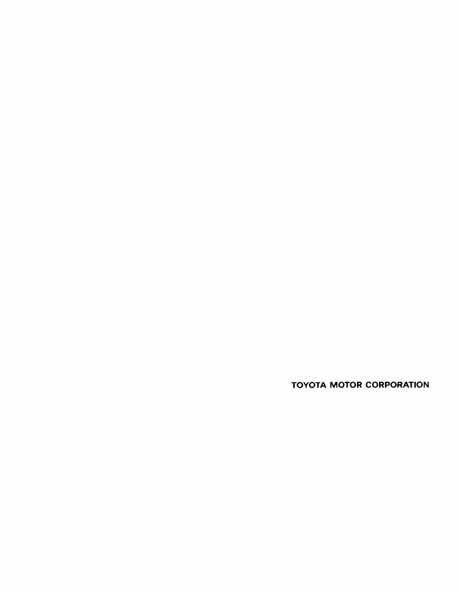
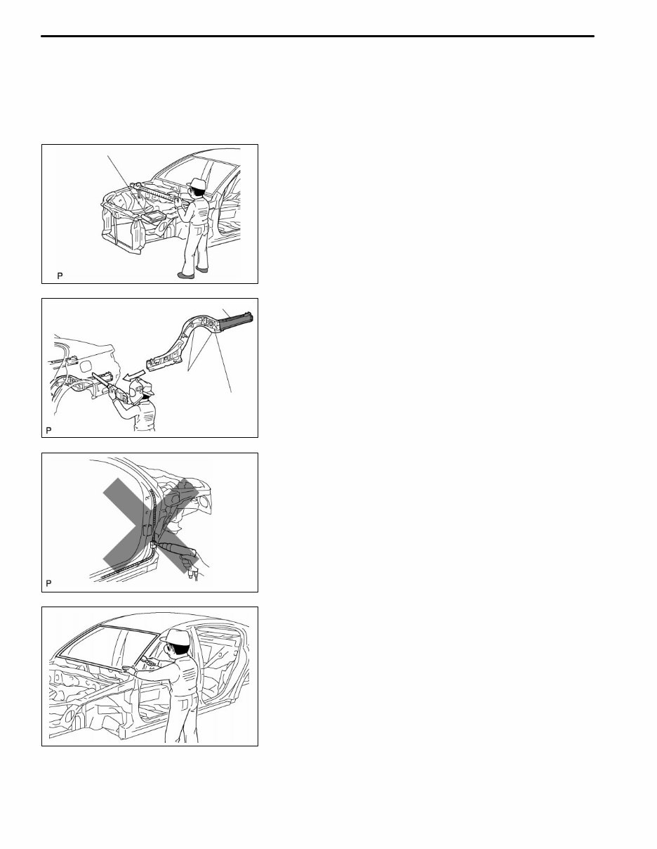
1. WORK PRECAUTIONS
(a) VEHICLE PROTECTION
(1) When welding, protect the painted surfaces, windows,
seats and carpet with heat resistant, fireproof covers.
(b) SAFETY
(1) Never stand in a direct line with the chain when using a
puller on the body or frame, and be sure to attach a
safety cable.
(2) Before performing repair work, check for fuel leaks.
If a leak is found, be sure to close the opening com-
pletely.
(3) If it is necessary to use a flame in the area of the fuel
tank, first remove the tank and plug the fuel line.
(c) SAFETY WORK CLOTHES
(1) In addition to the usual mechanic’s wear, cap and
safety shoes, the appropriate gloves, head protector,
glasses, ear plugs, face protector, dust-prevention
mask, etc. should be worn as the situation demands.
Code Name
A Dust-Prevention Mask
B Face Protector
C Eye Protector
D Safety Shoes
E Welder’s Glasses
F Ear Plugs
G Head Protector
H Welder’s Gloves
INTRODUCTION
F33014
F33015
IN-2
PRECAUTIONS FOR REPAIRING BODY
STRUCTURE PANELS
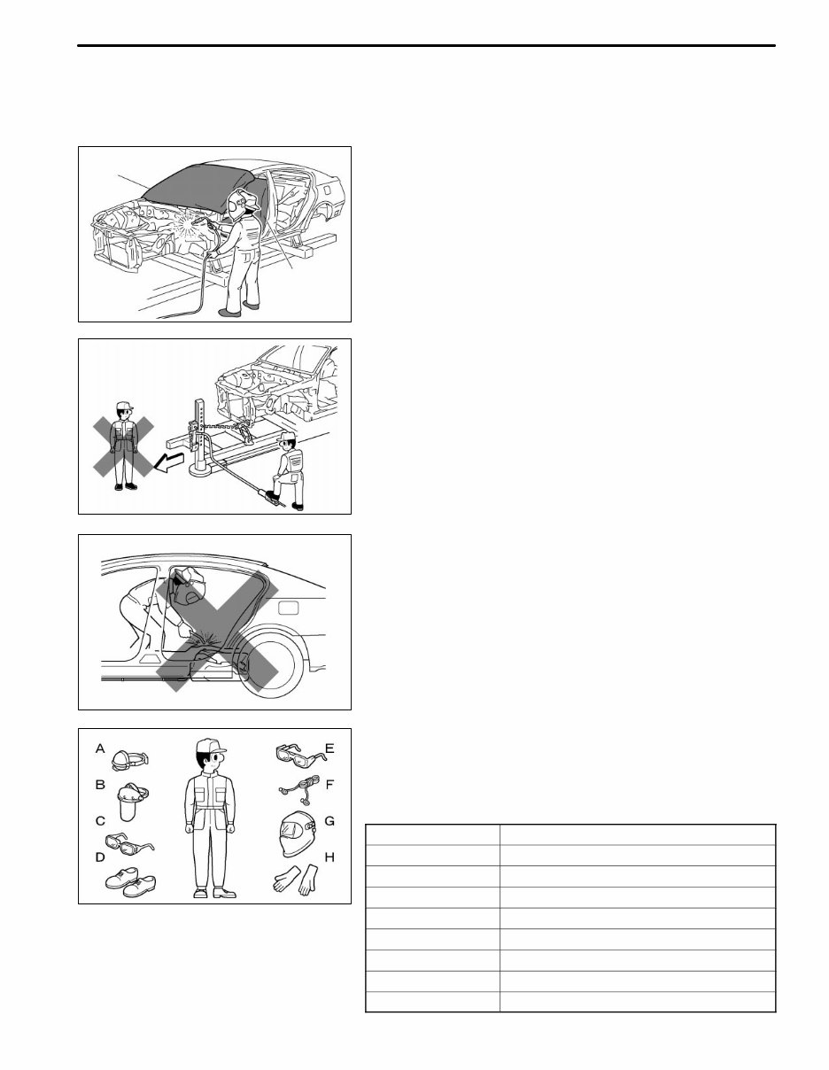
1. HEAT REPAIR FOR BODY STRUCTURE
PANELS
Toyota prohibits the use of the heat repair method on body
structure panels when repairing a vehicle damaged in a col-
lision.
Panels that have high strength and rigidity, as well as a long
life span for the automobile body are in high demand.
At Toyota, in order to fulfill these requirements, we use high
tensile strength steel sheets and rust preventive steel
sheets on the body. High tensile steel sheets are made with
alloy additives and a special heat treatment in order to im-
prove their strength.
To prevent the occurrence of rust for a long period of time,
the surface of the steel is coated with a zinc alloy.
If body structure parts are heat repaired with an acetylene
torch or other heating source, the crystalline organization of
the steel sheet will change and their strength of the steel
sheet will be reduced. The ability of the body to resist rust is
significantly lowered as well since the rust resistant zinc
coating is destroyed by heat and the steel sheet surface is
oxidized.
2. STRUCTURE PANEL KINKS
A sharp deformation angle on a panel that cannot be re-
turned to its original shape by pulling or hammering is
called a kink.
Structural parts are designed to perform in their original
shape. If parts are deformed in an accident, or if the de-
formed parts are repaired and reused, the parts may be un-
able to perform as intended.
It is necessary to replace the part where the kink has oc-
curred.
F33016
F33017
INTRODUCTION IN-3
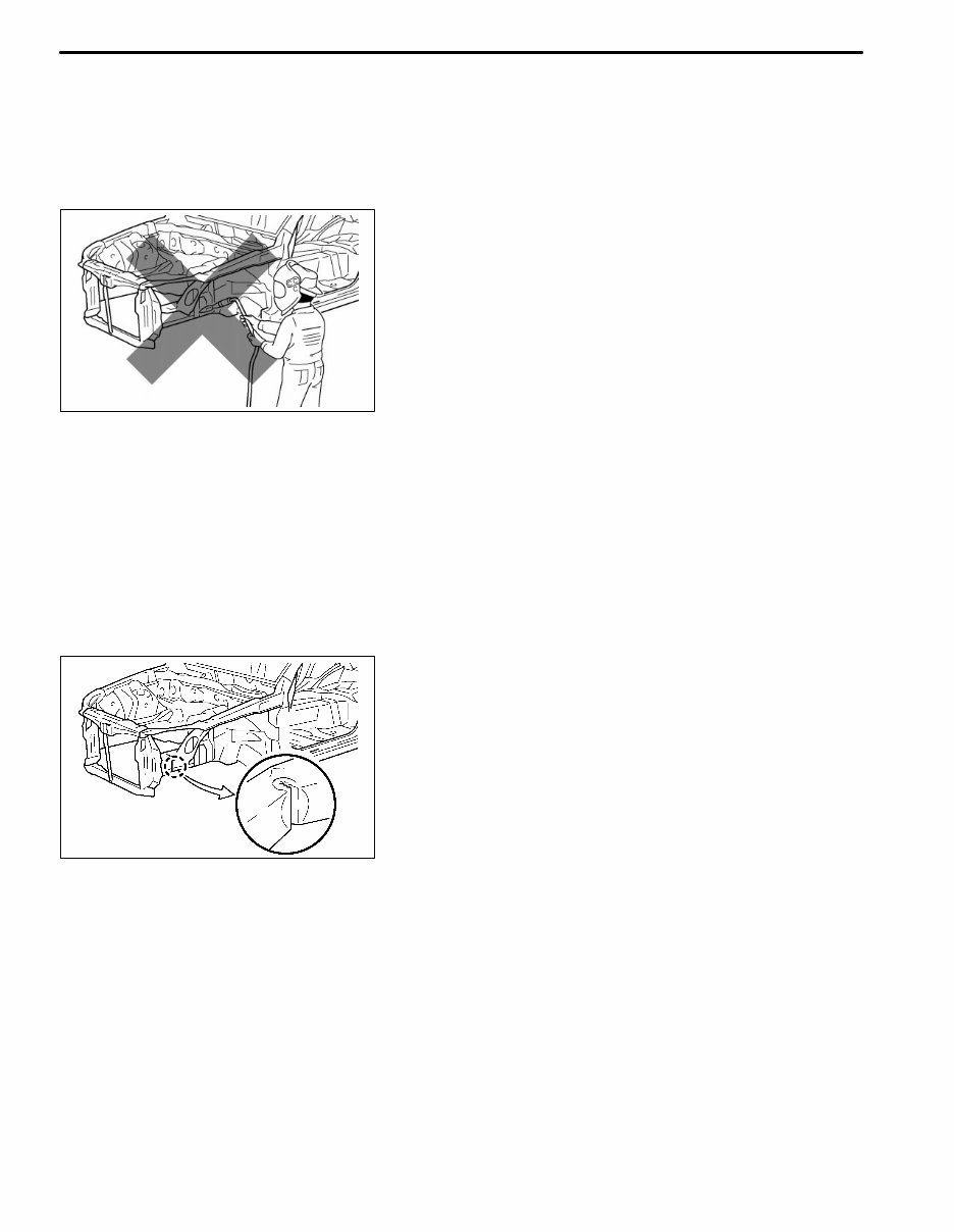
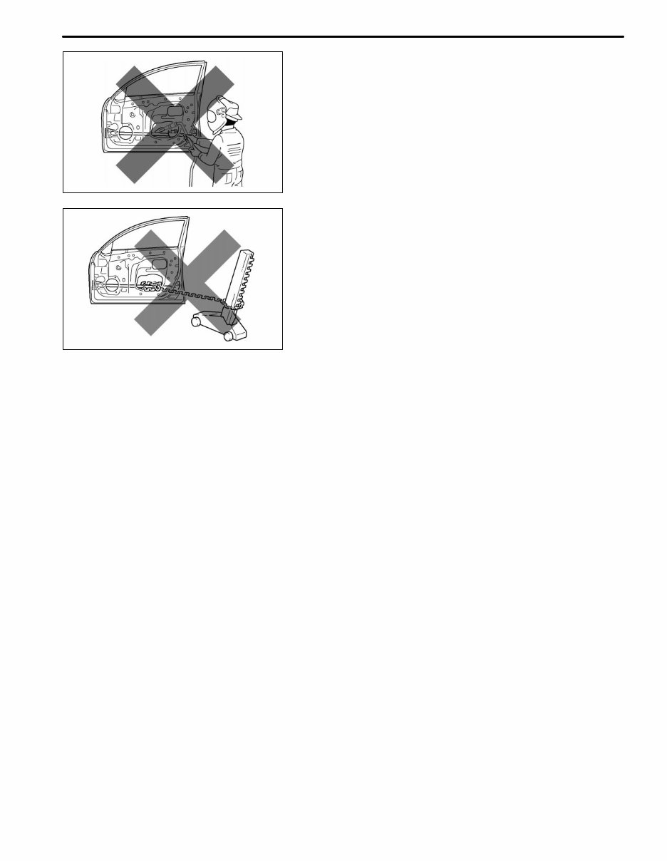
3. IMPACT BEAM REPAIR
The impact beam and bracket are necessary and important
parts that help reduce the probability of injury to passen-
gers in side collisions.
For impact beams, we use special high tensile strength
steel.
The high tensile strength steel maintains its special crystal-
line organization by heat treatment or alloy additives.
Structural parts are designed to perform in their original
shape. If parts are deformed in an accident, or if the de-
formed parts are repaired and reused, the parts may be un-
able to perform as intended.
If the impact beam or bracket is damaged, replace the door
assembly that has the damaged beam.
Also, the bumper reinforcement is a necessary and impor-
tant part that helps reduce the probability of injury to pas-
sengers in front collisions, and for the same reasons ex-
plained above, should be replaced if damaged.
F33020
F33021
F33022
F33007
Cutting Okay
Reinforcement
Corners
WRONG
Body Measument Diagrams
INTRODUCTION IN-4
PROPER AND EFFICIENT WORK
PROCEDURES
1. REMOVAL
(a) PRE-REMOVAL MEASURING
(1) Before removal or cutting operations, take measure-
ments in accordance with the dimensions diagram. Al-
ways use a puller to straighten a damaged body or
frame.
(b) CUTTING AREA
(1) Always cut in a straight line and avoid cutting rein-
forced areas.
(c) PRECAUTIONS FOR DRILLING OR CUTTING
(1) Check behind any area to be drilled or cut to ensure
that there are no hoses, wires, etc., that may be dam-
aged.
HINT: See “Handling Precautions on Related Compo-
nents” on page IN-9.
(d) REMOVAL OF ADJACENT COMPONENTS
(1) When removing adjacent components, apply protec-
tive tape to the surrounding body and your tools to pre-
vent damage.
HINT: See “Handling Precautions on Related Compo-
nents” on page IN-9.
F10011A
F33008
F33009
F33023
F33024
Less than
3 mm
Puncher
Air Saw
20 - 30 mm Overlap
INTRODUCTION IN-5
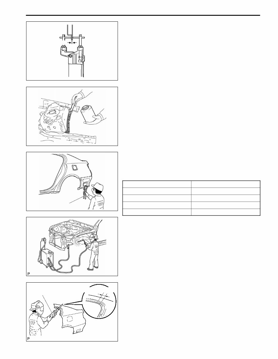
2. PREPARATION FOR INSTALLATION
(a) SPOT WELD POINTS
(1) When welding panels with a combined thickness of
over 3 mm (0.12 in.), use a MIG (Metal Inert Gas)
welder for plug welding.
HINT: Spot welding does not provide sufficient dura-
bility for panels with a combined thickness of over 3
mm (0.12 in.)
(b) APPLICATION OF WELD-THROUGH PRIMER
(SPOT SEALER)
(1) Remove the paint from the portion of the new parts
and body to be welded, and apply weld-through prim-
er.
(c) MAKING HOLES FOR PLUG WELDING
(1) For areas where a spot welder cannot be used, use a
puncher or drill to make holes for plug welding.
REFERENCE: mm (in.)
Thickness of welded portion Size of plug hole
1.0 (0.04) under ø 5 (0.20) over
1.0 (0.04) - 1.6 (0.06) ø 6.5 (0.26) over
1.7 (0.07) - 2.3 (0.09) ø 8 (0.31) over
2.4 (0.09) over ø 10 (0.39) over
(d) SAFETY PRECAUTIONS FOR ELECTRICAL
COMPONENTS
(1) When welding, there is a danger that electrical compo-
nents will be damaged by the electrical current flowing
through the body.
(2) Before starting work, disconnect the negative terminal
of the battery and ground the welder near the welding
location of the body.
(e) ROUGH CUTTING OF JOINTS
(1) For joint areas, rough cut the new parts, leaving 20 -
30 mm (0.79 - 1.18 in.) of overlap.
F33025
F10017A
F10018A
F33010
F10019A
WRONG
CORRECT WRONG
Tip Cutter
Old Spot Locations
New Spot Locations
INTRODUCTION IN-6
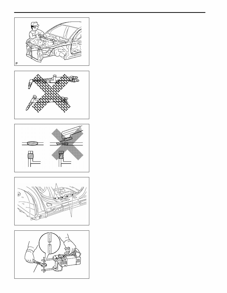
3. INSTALLATION
(a) PRE-WELDING MEASUREMENTS
(1) Always take measurements before installing under-
body or engine components to ensure correct assem-
bly. After installation, confirm proper fit.
(b) WELDING PRECAUTIONS
(1) The number of welding spots should be as follows.
Spot weld: 1.3 X No. of manufacturer’s spots.
Plug weld: More than No. of manufacturer’s plugs.
(2) Plug welding should be done with a MIG (Metal Inert
Gas) welder. Do not gas weld or braze panels at areas
other than where specified.
(c) POST-WELDING REFINISHING
(1) Always check the welded spots to ensure that they are
secure.
(2) When smoothing out the weld spots with a disc grind-
er, be careful not to grind off too much as this will weak-
en the weld.
(d) SPOT WELD LOCATIONS
(1) Avoid welding over previously welded areas.
(e) SPOT WELDING PRECAUTIONS
(1) The shape of the tip point of the spot welder signifi-
cantly affects the strength of the weld. Therefore,
maintain the tip point in the proper shape, and allow it
to cool after every five or six spots.
(2) Completely remove the paint from the areas to be spot
welded, including the seams and the surfaces that
come in contact with the welding tip.
(3) Use a sander to remove any burrs that are created
during spot welding.
F33011
F33012
F33013
Sealer Gun
INTRODUCTION IN-7
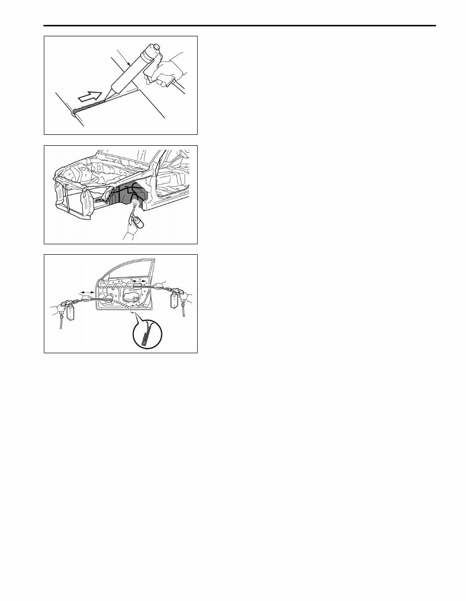
4. ANTI-RUST TREATMENT AFTER
INSTALLATION (BEFORE PAINTING
PROCESS)
(a) BODY SEALER APPLICATION
(1) For water-proofing and anti-corrosion measures, al-
ways apply the body sealer to the body panel seams
and hems of the doors, hood, etc.
(b) UNDERCOAT APPLICATION
(1) To prevent corrosion and protect the body from dam-
age by flying stones, always apply sufficient under
coating to the bottom surface of the under body and
inside of the wheel housings.
5. ANTI-RUST TREATMENT AFTER
INSTALLATION (AFTER PAINTING PROCESS)
(a) ANTI-RUST AGENT (WAX) APPLICATION
(1) To preserve impossible to paint areas from corrosion,
always apply sufficient anti-rust agent (wax) to the in-
side of the hemming areas of the doors and hood, and
around the hinges, or the welded surfaces inside the
box-shaped cross sections of the side members, body
pillars, etc.
F10024A
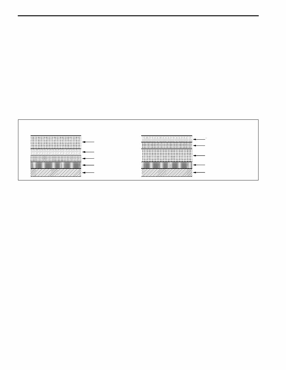
D Apply the anti-chipping paint after
the top coat.
D Apply the anti-chipping paint before
the second coat.
Anti-Chipping Paint
Top Coat
Second Coat
Under Coat (ED Primer)
Steel Metal
Top Coat
Second Coat
Anti-Chipping Paint
Under Coat (ED Primer)
Steel Metal
INTRODUCTION IN-8
6. ANTI-RUST TREATMENT BY PAINTING
REFERENCE:
Painting prevents corrosion and protects the sheet
metal from damage. In this section, anti-chipping paint
only for anti-corrosion purposes is described.
(a) ANTI-CHIPPING PAINT
(1) To prevent corrosion and protect the body from dam-
age by flying stones, etc., apply anti-chipping paint to
the rocker panel, wheel arch areas, balance panel,
etc.
HINT:
Depending on the model or the application area, there
are cases where the application of anti-chipping paint
is necessary before the second coat or after the top
coat.
You're Reading a Preview
What's Included?
Fast Download Speeds
Offline Viewing
Access Contents & Bookmarks
Full Search Facility
Print one or all pages of your manual
$36.99
Viewed 84 Times Today


Secure transaction
What's Included?
Fast Download Speeds
Offline Viewing
Access Contents & Bookmarks
Full Search Facility
Print one or all pages of your manual
$36.99
Discover the 2009 Toyota Camry Service & Repair Manual, a comprehensive guide tailored to aid Toyota Camry owners in vehicle maintenance and repair. This manual offers step-by-step instructions and detailed illustrations, catering to both DIY enthusiasts and professional mechanics.
Key features of the 2009 Toyota Camry Service & Repair Manual include:
- Complete coverage of all 2009 Toyota Camry models and trims, such as Base, LE, SE, and XLE
- Clear and concise instructions for all repair and service tasks
- Comprehensive troubleshooting guide
- Detailed electrical wiring diagrams
- Maintenance schedules and procedures
- Do-it-yourself repair tips and tricks
- Handy reference for regular maintenance and repairs
Whether it's routine maintenance, part replacements, or issue troubleshooting, the 2009 Toyota Camry Service & Repair Manual is the ultimate resource. Take charge of your vehicle's upkeep and ensure the job is done accurately without relying on costly dealership visits or mechanic services.


