

2007 Toyota Camry Service & Repair Manual
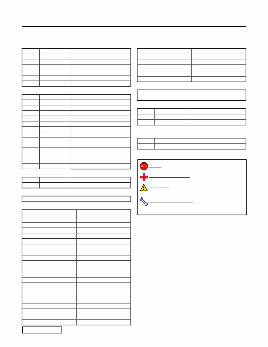
What's Included?
Fast Download Speeds
Offline Viewing
Access Contents & Bookmarks
Full Search Facility
Print one or all pages of your manual
TOYOTA CAMRY 2007 - TVIP V4 REMOTE ENGINE STARTER (RES)
Preparation Smart Key
Page 1 of 28 pages Issue: C 07/18/06
Part Number: 08586-3T950
NOTE: Part number of this accessory may not be
the same as the part number shown.
Kit Contents
Item # Quantity Reqd. Description
1 1 Wire Harness
2 1 RES ECU
3 1 BUS ECU
4 1 ECU Mounting Bracket
5 1 Butyl Tape
6 1 Support Bracket
Hardware Bag Contents
Item # Quantity Reqd. Description
1 1 Splicing Connector
2 4 Nut
3 8 Small Foam Tapes
4 30 Wire Ties
5 2 Window Labels
6 2 Key Tag
7 1 Shift Tag
8 1 Key Label
(For Remote Control Key)
9 2 Caution Label
(For Engine Compartment)
10 1 Owner’s Manual
11 1 Butyl Tape
Additional Items Required For Installation
Item # Quantity Reqd. Description
Conflicts
Recommended Tools
Personal & Vehicle
Protection
Notes
Safety Glasses
Safety Gloves (Optional)
Vehicle Protection Blankets, Part Boxes
Special Tools Notes
Scan Tool and Software
Card
01001271 with Version 13.3
Software (or later)
Wiring Terminal Tool IADS #: ALL 02-016-03
Electrical Phillips Head
Screw Driver
Snap On SDEP21 No. 1
Phillips
Installation Tools Notes
Phillips Head Screwdriver #2, screwdriver or tip
Socket 10mm
Nylon Panel Removal Tool e.g. Panel Pry Tool #1
Toyota SST # 00002-06001-01
Pneumatic/Electric Wrench
Side Cutters
Torque Wrench (for battery) 36 in.-lbf
Wrench 10mm, 12mm
Utility Knife
Pliers
Needlenose Pliers
Marker
Special Chemicals Notes
Cleaner 3M
TM
Prepsolvent-70
Glass Cleaner Household Windex
General Applicability
Note: Camry with Smart Key, and automatic transmission
only.
Recommended Sequence of Application
Item # Accessory
1 V4/V2/V5 Security
2 Satellite Radio
*Mandatory
Vehicle Service Parts (may be required for reassembly)
Item # Quantity Reqd. Description
Legend
STOP: Damage to the vehicle may occur. Do not
proceed until process has been complied with.
OPERATOR SAFETY: Use caution to avoid risk of
injury.
CAUTION: A process that must be carefully observed
in order to reduce the risk of damage to the
accessory/vehicle and to ensure a quality installation.
TOOLS & EQUIPMENT: Used in Figures calls out the
specific tools and equipment recommended for this
process.
TOYOTA CAMRY 2007 - TVIP V4 REMOTE ENGINE STARTER (RES)
Smart Key
Page 2 of 28 pages Issue: C 07/18/06
Care must be taken when installing this accessory to ensure damage does not occur to the vehicle. The installation of this
accessory should follow approved guidelines to ensure a quality installation.
These guidelines can be found in the "Accessory Installation Practices" document.
This document covers such items as:-
• Vehicle Protection (use of covers and blankets, cleaning chemicals, etc.).
• Safety (eye protection, rechecking torque procedure, etc.).
• Vehicle Disassembly/Reassembly (panel removal, part storage, etc.).
• Electrical Component Disassembly/Reassembly (battery disconnection, connector removal, etc.).
Please see your Toyota dealer for a copy of this document.
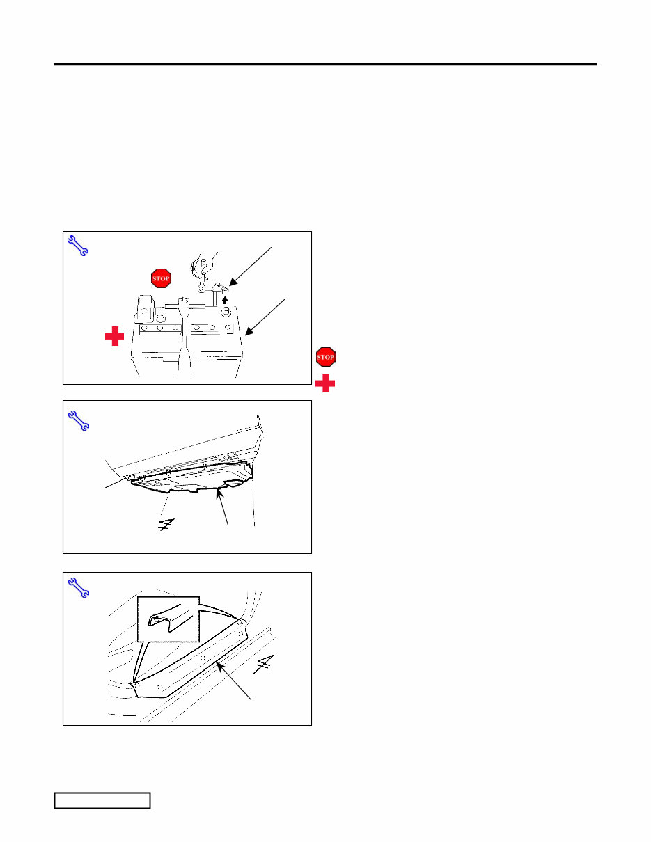
1. Vehicle Disassembly.
(a) Take note of the battery cable installation
position, as this will need to be re-installed in
the same position after installation completion.
(b) Remove the negative battery cable.
(Fig. 1-1)
(1) Protect the fender before starting.
(2) Do not touch the positive terminal with
any tool removing the cable.
(c) Remove the glove box under-dash cover.
(Fig. 1-2)
(d) Remove the passenger’s step cover.
(Fig. 1-3)
Step Cover
Fig. 1-3
Nylon Panel Removal
Fig. 1-2 Under-Dash Cover
Nylon Panel Removal Tool
Fig. 1-1
10mm Wrench
Negative Battery Cable
Battery
TOYOTA CAMRY 2007 - TVIP V4 REMOTE ENGINE STARTER (RES)
Smart Key
Page 3 of 28 pages Issue: C 07/18/06
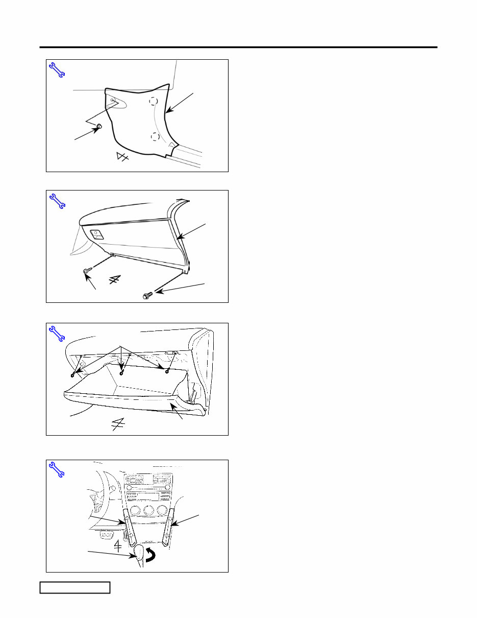
(e) Remove the passenger’s cowl cover.
(Fig. 1-4)
(1) Remove one nut securing the cowl cover.
(f) Remove one screw and one bolt from the glove
box assembly. (Fig. 1-5)
(g) Open the glove box door and remove three
screws securing the glove box assembly.
(Fig. 1-6)
(h) Confirm that the emergency brake is set.
(i) Move the shifter to the "D" position.
(Fig. 1-7)
(j) Remove the left and right side trim panels from
the center cluster. (Fig. 1-7)
(k) Remove the shift knob. (Fig. 1-7)
Screw Fig. 1-5
10mm Wrench, Phillips Screwdriver
Bolt
Glove Box
Assembly
Phillips Screwdriver
Fig. 1-6
Screws (x3)
Glove Box Assembly
Cowl Cover
Nut
Fig. 1-4
Nylon Panel Removal Tool
Trim
Panel
Fig. 1-7
Nylon Panel Removal Tool
Trim
Panel
Gear Shift
Knob
TOYOTA CAMRY 2007 - TVIP V4 REMOTE ENGINE STARTER (RES)
Smart Key
Page 4 of 28 pages Issue: C 07/18/06
Fig. 1-9
Screwdriver
Screws
(x2)
Storage
Box
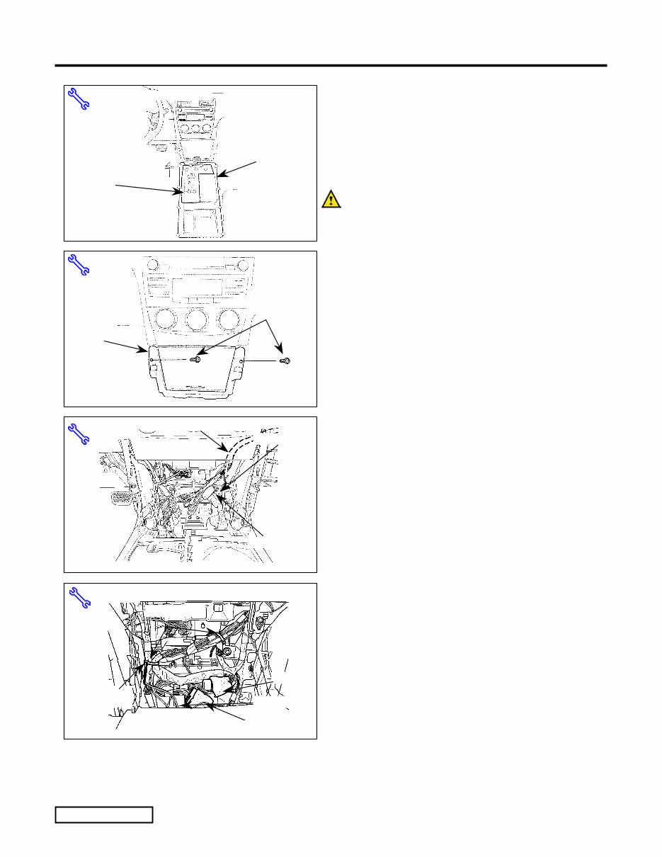
(l) Loosen the upper panel of the floor console
panel. (Fig. 1-8)
(1) If the vehicle is equipped with seat
heaters, disconnect any connectors from
the console panel.
(m) Loosen the console panel. (Fig 1-8)
CAUTION: Place a protective sheet
underneath the center console panel after it is
loosened.
(n) Remove the center console storage box.
(Fig. 1-9)
(1) Remove the two screws securing the
storage box.
(2) Disconnect any connectors.
.
2. RES Harness Installation.
(a) Route the portion of the RES harness
containing the white 8P connectors, red wire,
relay, fuse, 8P connector (include the empty
female connector) and female terminal green
wire from the glove box area into the center
console area. (Fig. 2-1)
(b) Locate the white taped marker on the RES
harness, then secure it to the left side of the
vehicle harness in the center console area with
one wire tie. Then, secure one wire tie on the
right side of the vehicle harness. (Fig. 2-2)
Fig. 1-8
Nylon Panel Removal Tool
Console
panel
Upper
Console
Panel
Fig. 2-1
8P (White)
TVIP Wire Harness
Wire Tie
Side Cutter
Fig. 2-2
Wire Tie (x2)
White Tape
Marker
Relay
Side Cutter
Big 8P (White)
RED Wire
TOYOTA CAMRY 2007 - TVIP V4 REMOTE ENGINE STARTER (RES)
Smart Key
Page 5 of 28 pages Issue: C 07/18/06
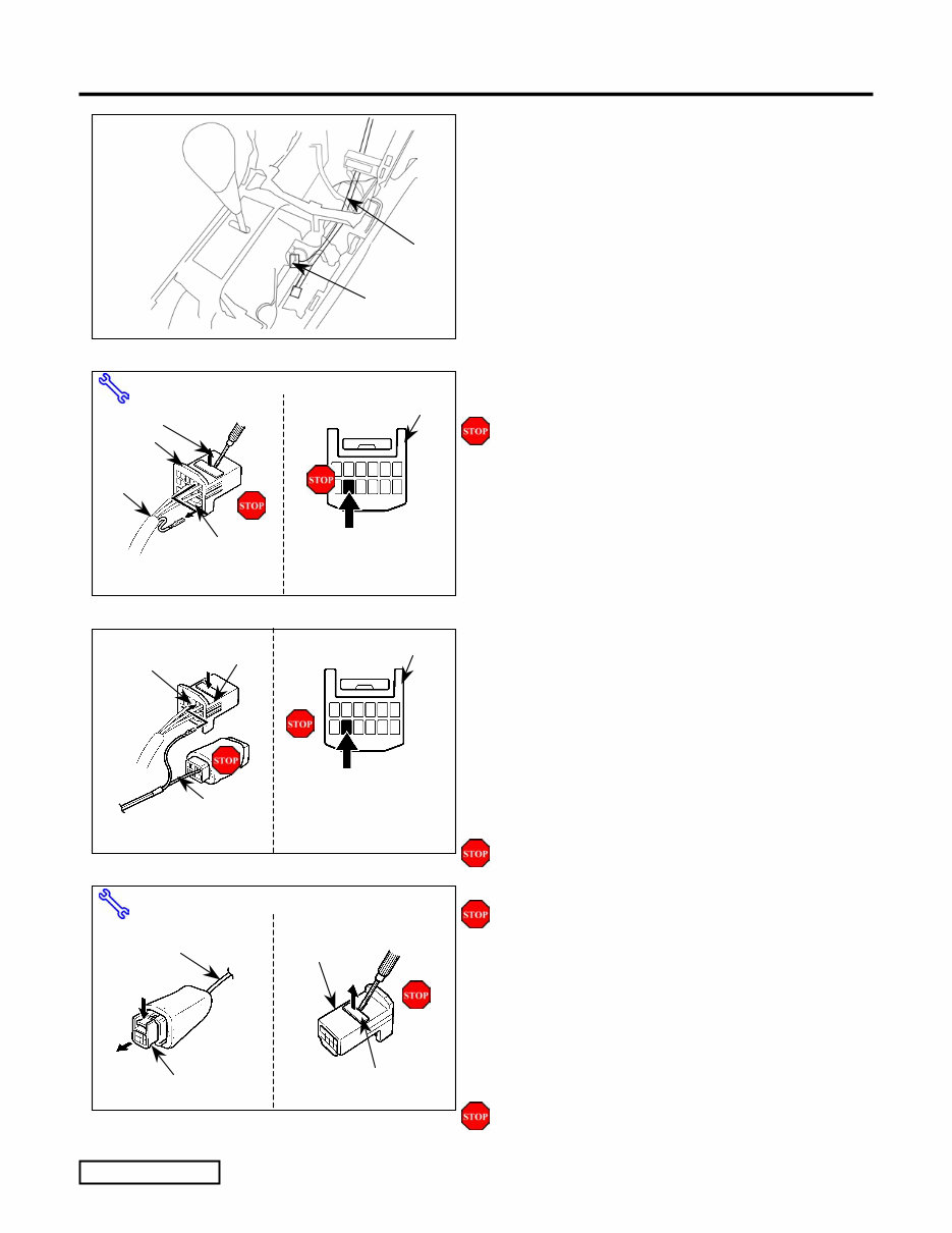
(c) Route the RES harness’ small white 8P
connector (include the empty female connector)
and green wire terminal toward the gear shift
area. (Fig. 2-3)
(d) Locate the white 12P connector on the right
side of the gearshift area, then disconnect it.
(Fig. 2-3)
(e) Use a small jeweler's screwdriver to lift up the
terminal retainer on the black 12P connector.
(Fig. 2-4)
(1) Do not pull out the retainer.
(f) Locate the GREEN wire in the bottom row,
second space from the left of the white 12P
connector. Using a pick (or wiring terminal
tool (PPO)), release and pull out the terminal
for the GREEN wire. (Fig. 2-4)
(1) Turn the connector so the wires face you
and the tab is on top.
(g) Insert the terminal at the end of the RES
harness’ GREEN wire into the bottom row,
second space from the left, of the white 12P
connector, then close the retainer. (Fig. 2-5)
(1) Turn the connector so the wire faces you
and the tab is on top.
(2) Verify the terminal is inserted and seated
properly.
(3) The terminal should not come out when
pulled lightly from the back.
(h) Disconnect the empty white 8P female
connector plugged into the RES harness. Using
a small jeweler's screwdriver, lift up the
terminal retainer on the back of the empty
connector. (Fig. 2-6)
(1) Do not pull out the retainer.
Fig. 2-3
12P (White)
TVIP Wire
Harness
Fig. 2-4
Vehicle Harness'
GREEN/RED
Wire Terminal
12P
Wire Side View
GREEN
Retainer
12P
Jewelers' Screwdriver, Wiring Terminal Tool
Protect
Cover
Fig. 2-5
12P
12P
V5 Harness'
GREEN Wire
Terminal
Wire Side View
GREEN
Retainer
Fig. 2-6
Retainer
V5 Harness'
GREEN Wire
Jewelers' Screwdriver, Wiring Terminal Tool
8P (Black)
(Female)
8P (Black)
(Female)
You're Reading a Preview
What's Included?
Fast Download Speeds
Offline Viewing
Access Contents & Bookmarks
Full Search Facility
Print one or all pages of your manual
$36.99
Viewed 86 Times Today


Secure transaction
What's Included?
Fast Download Speeds
Offline Viewing
Access Contents & Bookmarks
Full Search Facility
Print one or all pages of your manual
$36.99
The 2007 Toyota Camry Service & Repair Manual is a comprehensive resource for servicing and repairing your vehicle. Whether you're a professional mechanic or a DIY enthusiast, this manual provides valuable assistance in maintaining and fixing your 2007 Toyota Camry.
Inside this manual, you'll find detailed explanations, step-by-step instructions, and diagrams covering various aspects of servicing your Camry, from routine maintenance tasks to more complex repairs.
Key features of this manual include:
- Detailed information on engine, transmission, and drivetrain systems
- Guidance on electrical and electronic systems
- Diagnostic procedures and troubleshooting tips
- Instructions for handling brakes, suspension, and steering components
- Specifications and diagrams for body and interior components
Models covered in this manual:
- 2007 Toyota Camry LE
- 2007 Toyota Camry SE
- 2007 Toyota Camry XLE
The 2007 Toyota Camry Service & Repair Manual equips you to confidently tackle any maintenance or repair task on your vehicle, ensuring its longevity and performance.


