NOTICE Always follow the directions given in the above repair manuals when handling supplemental restraint system components (such as removal, installation, inspection, etc.) in order to prevent accidents and supplemental restraint system malfunction. E2005 All rights reserved. This book may not be reproduced or copied, in whole or in part, without the written permission of Toyota Motor Corporation. First Printing : Jul. 25, 2005 01–050725–00 FOREWORD This wiring diagram manual has been prepared to provide information on the electrical system of the 2006 AVALON. Applicable models: GSX30 Series Refer to the following manuals for additional service specifications and repair procedures for these models: Manual Name Pub. No. D 2006 AVALON Repair Manual D 2006 TOYOTA New Car Features RM00A0U NM0010U All information in this manual is based on the latest product information at the time of publication. However, specifications and procedures are subject to change without notice.
2 AVALON (EM00A0U) A INTRODUCTION This manual consists of the following 13 sections: No. Section Description A INDEX Index of the contents of this manual. A INTRODUCTION Brief explanation of each section. B HOW TO USE THIS MANUAL Instructions on how to use this manual. C TROUBLE– SHOOTING Describes the basic inspection procedures for electrical circuits. D ABBREVIATIONS Defines the abbreviations used in this manual. E GLOSSARY OF TERMS AND SYMBOLS Defines the symbols and functions of major parts. F RELAY LOCATIONS Shows position of the Electronic Control Unit, Relays, Relay Block, etc. This section is closely related to the system circuit. G ELECTRICAL WIRING ROUTING Describes position of Parts Connectors, Splice points, Ground points, etc. This section is closely related to the system circuit. H INDEX Index of the system circuits. H SYSTEM CIRCUITS Electrical circuits of each system are shown from the power supply through ground points. Wiring connections and their positions are shown and classified by code according to the connection method. (Refer to the section, ”How to use this manual”). The ”System Outline” and ”Service Hints” useful for troubleshooting are also contained in this section. I GROUND POINT Shows ground positions of all parts described in this manual. J POWER SOURCE (Current Flow Chart) Describes power distribution from the power supply to various electrical loads. K CONNECTOR LIST Describes the form of the connectors for the parts appeared in this book. This section is closely related to the system circuit. L PART NUMBER OF CONNECTORS Indicates the part number of the connectors used in this manual. M OVERALL ELECTRICAL WIRING DIAGRAM Provides circuit diagrams showing the circuit connections.
AVALON (EM00A0U) 3 HOW TO USE THIS MANUAL B This manual provides information on the electrical circuits installed on vehicles by dividing them into a circuit for each system. The actual wiring of each system circuit is shown from the point where the power source is received from the battery as far as each ground point. (All circuit diagrams are shown with the switches in the OFF position.) When troubleshooting any problem, first understand the operation of the circuit where the problem was detected (see System Circuit section), the power source supplying power to that circuit (see Power Source section), and the ground points (see Ground Point section). See the System Outline to understand the circuit operation. When the circuit operation is understood, begin troubleshooting of the problem circuit to isolate the cause. Use Relay Location and Electrical Wiring Routing sections to find each part, junction block and wiring harness connectors, wiring harness and wiring harness connectors and ground points of each system circuit. Internal wiring for each junction block is also provided for better understanding of connection within a junction block. Wiring related to each system is indicated in each system circuit by arrows (from__, to__). When overall connections are required, see the Overall Electrical Wiring Diagram at the end of this manual.
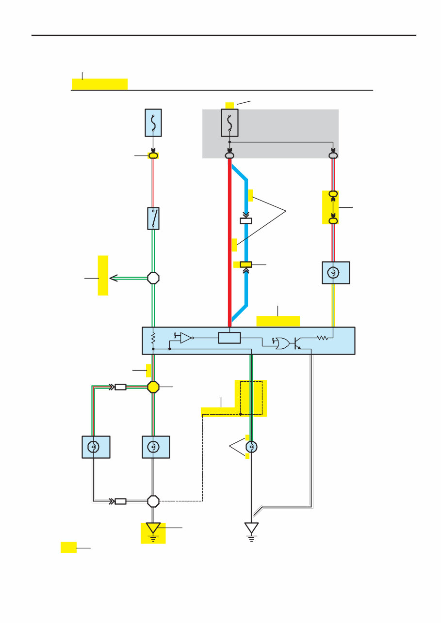
[B] W – R G – W Skid Control ECU with Actuator G – W H7 Y – G Combination Meter R – L Rear Lights R – L (S/D) (S/D) (S/D) (W/G) G – B W – B W – B Rear Combination Lamp (LH) H9 W – B W – B Rear Combination Lamp (RH) J7 W – B G – R Stop Stop G – R G – R 7 L L R L Stop Light 2 (BAT) 15A STOP (IG) IB IB 7.5A GAUGE 3 4 1 [A] H6 Stop Lamp SW G – W 1 2 [D] [C] [E] [F] [G] [M] H4 Light Failure Sensor 3C 3C 15 CH1 CH1 14 7 15 4 8 13 4 50 [J] [H] [N] [K] [L] [I] 11 H17 Center Stop Lamp (Shielded) H1 H2 HJ1 W – B G – R HJ1 1 2 6 3 3 4 1 1 1 2 4 AVALON (EM00A0U) B HOW TO USE THIS MANUAL * The system shown here is an EXAMPLE ONLY. It is different to the actual circuit shown in the SYSTEM CIRCUITS SECTION.
If you are in need of a repair manual for your 2011 Toyota Avalon, look no further. This comprehensive manual is suitable for both professional mechanics and DIY enthusiasts. In the past, obtaining service information required purchasing a traditional book format manual at a higher cost. However, this accessible digital manual provides a more cost-effective and convenient alternative.
Whether you are looking to address brake repairs, suspension component replacements, engine issues, or standard maintenance tasks, this manual has you covered. It contains a wealth of service information related to brakes, engine, suspension, steering, drivetrain, electrical systems, heating, air conditioning, and more.
By utilizing this manual, you can save a significant amount of money on vehicle maintenance. Professional mechanics often charge high fees for their services, making a DIY approach a cost-effective option. This 2011 Toyota Avalon repair manual is compatible with Windows, Mac computers, smartphones, and tablets, ensuring ease of use across various devices.