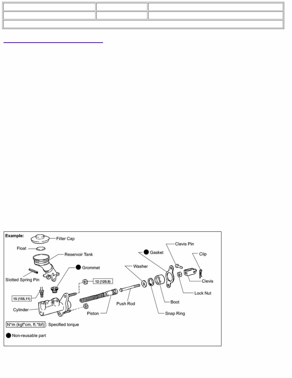
Last Modified: 8-24-2021 6.10:8.0.50 Doc ID: RM000000UYV05TX Model Year Start: 2009 Model: Avalon Prod Date Range: [08/2008 - ] Title: INTRODUCTION: HOW TO USE THIS MANUAL: GENERAL INFORMATION; 2009 MY Avalon [08/2008 - ] GENERAL INFORMATION 1. GENERAL DESCRIPTION (a) This manual is written in accordance with SAE J2008. (b) Repair operations can be separated mainly in the following 3 processes: (1) Diagnosis (2) Removing/Installing, Replacing, Disassembling/Reassembling, Checking and Adjusting (3) Final Inspection (c) The following procedures are omitted from this manual. However, these procedures are essential and must be performed when applicable. (1) Use a jack or lift to perform operations (2) Cleaning removed parts (3) Performing a visual check 2. INDEX (a) An alphabetical INDEX section is provided at the end of the book as a reference to help you find the item to be repaired. 3. PREPARATION (a) Use of Special Service Tools (SST) and Special Service Materials (SSM) may be required, depending on the repair procedure. Be sure to use SST and SSM when they are required and follow the working procedure properly. A list of SST and SSM is in the "Preparation" section of this manual. 4. REPAIR PROCEDURES (a) A component illustration is placed under the title where necessary. (b) Non-reusable parts, grease application areas, precoated parts and torque specifications are noted in the component illustrations. (c) Torque specifications, grease application areas and non-reusable parts are emphasized in the procedures. HINT:
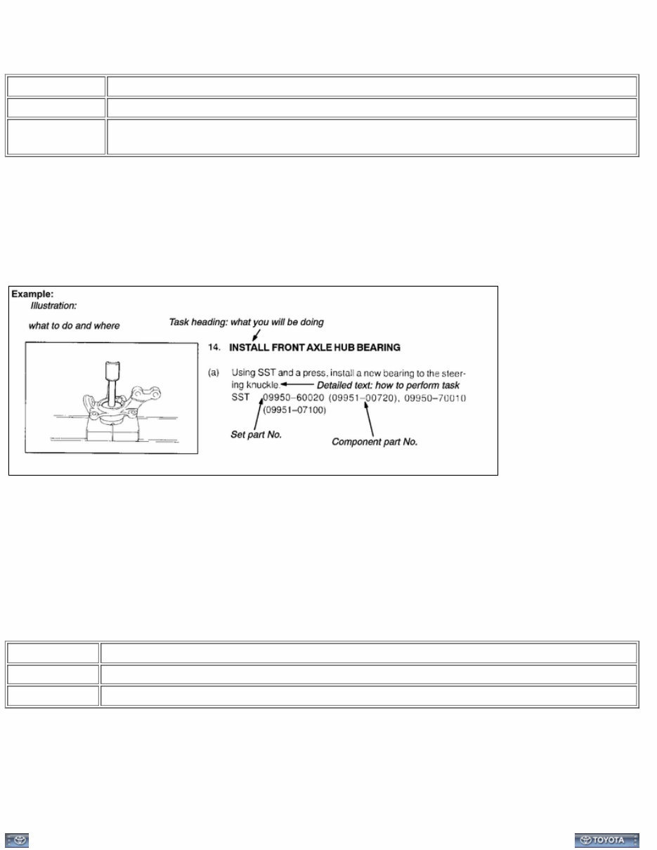
There are cases where such information can only be explained by using an illustration. In these cases, all the information such as torque, oil, etc. are described in the illustration. (d) Only items with key points are described in the text. What to do and other details are placed in illustrations next to the text. Both the text and illustrations are accompanied by standard values and notices. Illustration What to do and where to do it Task heading What work will be performed Explanation test How to perform the task Also has information such as specifications and warnings, which are written in boldface text (e) Illustrations of similar vehicle models are sometimes used. In those cases, miner details may be different from the actual vehicle. (f) Procedures are presented in a step-by-step format: (1) The illustration shows what to do and where to do it. (2) The task heading tells what to do. (3) The explanation text tells how to perform the task. It also has information such as specifications and warning. HINT: This format provides an experienced technician with a FAST TRACK to the necessary information. The task headings are easy to read and the text below the task heading provides detailed information. Important specifications and warnings are always written in bold type. 5. SERVICE SPECIFICATIONS (a) SPECIFICATIONS are presented in bold-faced text throughout the manual. The specifications are also found in the "Service Specifications" section for quick reference. 6. TERMS DEFINITION CAUTION Possibility of injury to you or other people. NOTICE Possibility of damage to components being repaired. HINT Provides additional information to help you perform repairs. 7. INTERNATIONAL SYSTEM OF UNITS (a) The units used in this manual comply with the SI UNIT (International System of Units) standard. Units from the metric system and the English systems are also provided. Example: Torque: 30 N·m {310 kgf·cm, 22ft·lbf}
Last Modified: 8-24-2021 6.10:8.0.50 Doc ID: RM000000UYW06NX Model Year Start: 2009 Model: Avalon Prod Date Range: [08/2008 - ] Title: INTRODUCTION: IDENTIFICATION INFORMATION: VEHICLE IDENTIFICATION AND SERIAL NUMBERS; 2009 MY Avalon [08/2008 - ] VEHICLE IDENTIFICATION AND SERIAL NUMBERS 1. VEHICLE IDENTIFICATION NUMBER (a) The vehicle identification number is stamped on the vehicle identification number plate and certification label, as shown in the illustration. A: Vehicle Identification Number Plate B: Certification Label 2. ENGINE SERIAL NUMBER AND TRANSAXLE SERIAL NUMBER (a) The engine serial number is stamped on the cylinder block of the engine. A: Engine Serial Number (b) The transaxle serial number is stamped on the housing as shown in the illustration. B: Transaxle Serial Number
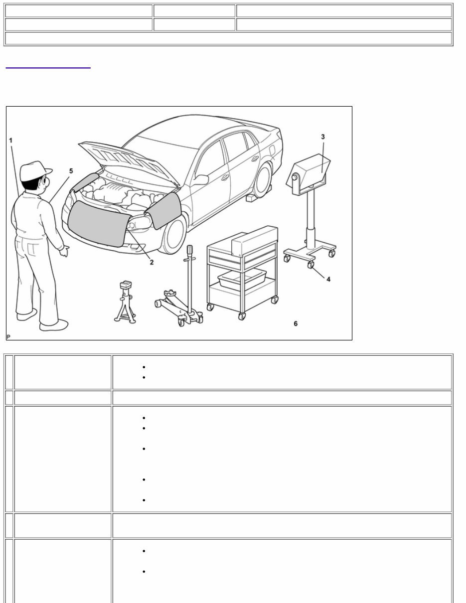
Last Modified: 8-24-2021 6.10:8.0.50 Doc ID: RM000000UYX06FX Model Year Start: 2009 Model: Avalon Prod Date Range: [08/2008 - ] Title: INTRODUCTION: REPAIR INSTRUCTION: PRECAUTION; 2009 MY Avalon [08/2008 - ] PRECAUTION 1. BASIC REPAIR HINT (a) HINTS ON OPERATIONS 1 Attire Always wear a clean uniform. Hat and safety shoes must be worn. 2 Vehicle protection Prepare a grille cover, fender cover, seat cover and floor mat before starting the operation. 3 Safe operation When working with 2 or more persons, be sure to check safety for one another. When working with the engine running, make sure to provide ventilation for exhaust fumes in the workshop. If working on high temperature, high pressure, rotating, moving, or vibrating parts, wear appropriate safety equipment and take extra care not to injure yourself or others. When jacking up the vehicle, be sure to support the specified location with a safety stand. When lifting up the vehicle, use appropriate safety equipment. 4 Preparation of tools and measuring gauge Before starting operation, prepare a tool stand, SST, gauge, oil and parts for replacement. 5 Removal and installation, disassembly and assembly operations Diagnose with a thorough understanding of proper procedures and of the reported problem. Before removing the parts, check the general condition of the assembly and for deformation and damage.
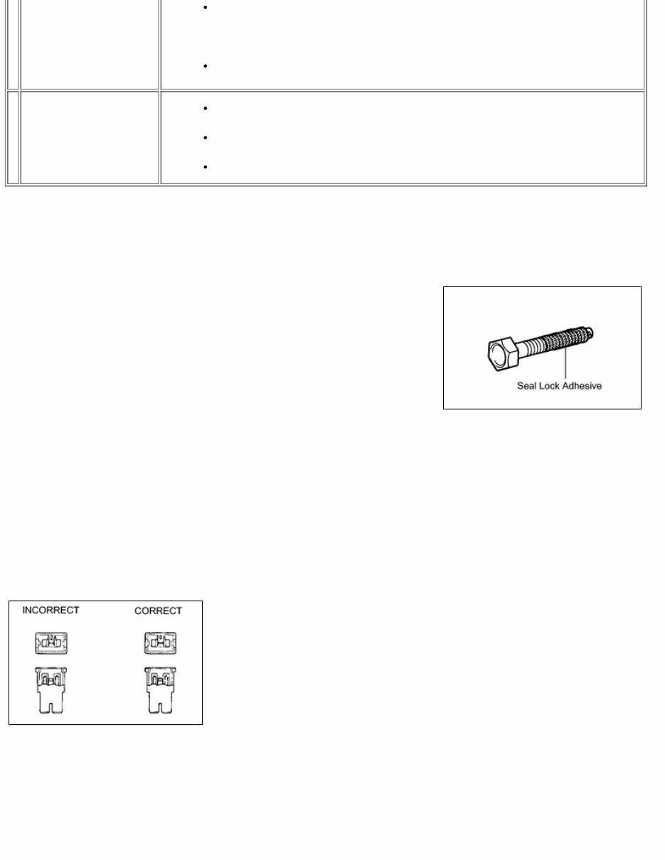
When the assembly is complicated, take notes. For example, note the total number of electrical connections, bolts, or hoses removed. Add matchmarks to insure reassembly of components in the original positions. Temporarily mark hoses and their fittings if needed. Clean and wash the removed parts if necessary and assemble them after a thorough check. 6 Removed parts Place the removed parts in a separate box to avoid mixing them up with the new parts or contaminating the new parts. For non-reusable parts such as gaskets, O-rings, and self-locking nuts, replace them with new ones as instructed in this manual. Retain the removed parts for customer inspection, if requested. (b) JACKING UP AND SUPPORTING VEHICLE (1) Care must be taken when jacking up and supporting the vehicle. Be sure to lift and support the vehicle at the proper locations. (c) PRECOATED PARTS (1) Precoated parts are bolts and nuts that are coated with a seal lock adhesive at the factory. (2) If a precoated part is retightened, loosened or moved in any way, it must be recoated with the specified adhesive. (3) When reusing a precoated part, clean off the old adhesive and dry the part with compressed air. Then apply new seal lock adhesive appropriate to that part. (4) Some seal lock agents harden slowly. You may have to wait for the seal lock adhesive to harden. (d) GASKETS (1) When necessary, use a sealer on gaskets to prevent leaks. (e) BOLTS, NUTS AND SCREWS (1) Carefully follow all the specifications for tightening torques. Always use a torque wrench. NOTICE: Perform the torque with the lower limit value of the torque tolerance. (f) FUSES (1) When inspecting a fuse, check that the wire of the fuse is not broken. (2) If the wire of a fuse is broken, confirm that there are no shorts in its circuit. (3) When a fuse is replaced, a fuse with the same amperage rating must be used.
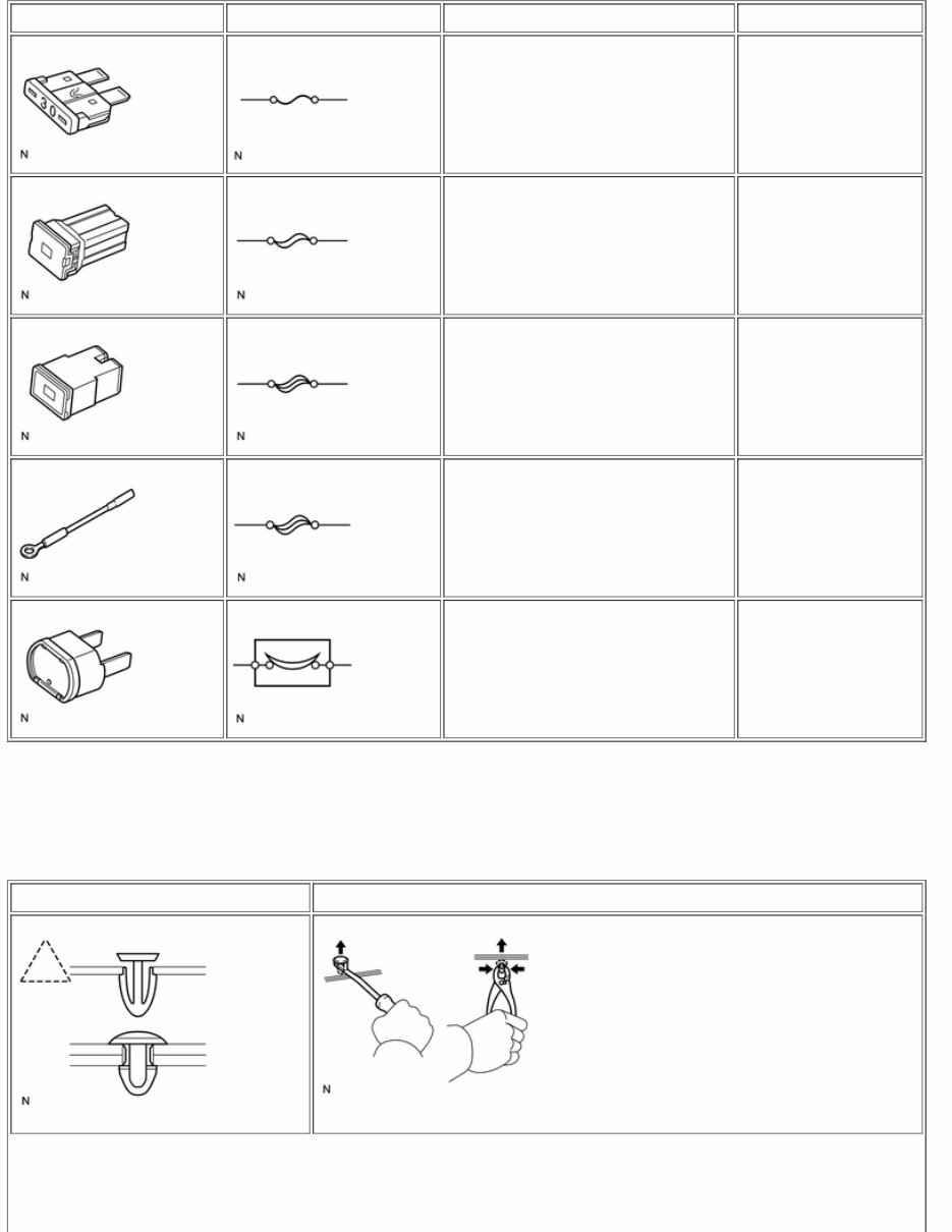
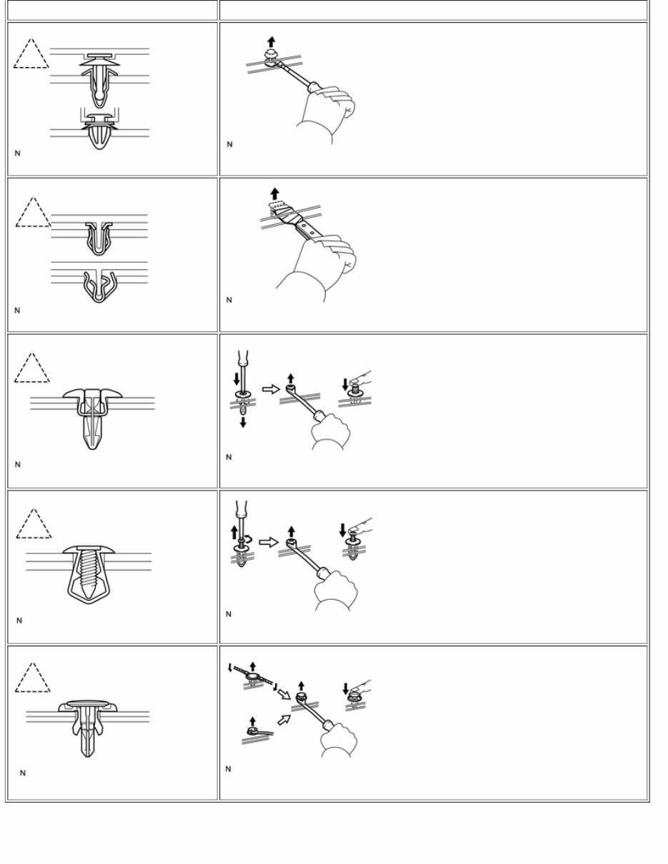
ILLUSTRATION SYMBOL PART NAME ABBREVIATION FUSE FUSE MEDIUM CURRENT FUSE M-FUSE HIGH CURRENT FUSE H-FUSE FUSIBLE LINK FL CIRCUIT BREAKER CB (g) CLIPS (1) The removal and installation methods of typical clips used in body parts are shown in the table below. HINT: If clips are damaged during a procedure, always replace the damaged clip with a new clip. SHAPE (EXAMPLE) REMOVAL/INSTALLATION Remove clips with clip remover or pliers.
SHAPE (EXAMPLE) REMOVAL/INSTALLATION Remove fasteners with clip remover or screwdriver. Remove clips with wide scraper to prevent panel damage. Remove clips by pushing center pin through and prying out shell. Remove clips by unscrewing center pin and prying out shell. Remove clips by prying out pin and then prying out shell. (h) CLAWS (1) The removal and installation methods of typical claws used for vehicle body parts are shown in the table below.
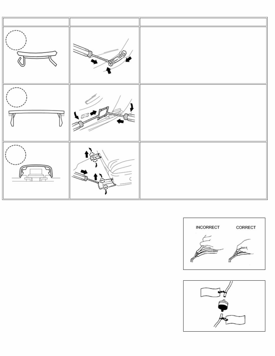
HINT: If claws are damaged during a procedure, always replace the damaged claws with a new caps or covers. SHAPE (EXAMPLE) ILLUSTRATION PROCEDURES 1. Using a screwdriver, detach the claws and remove the cap or covers. 1. Using a screwdriver, detach the claws and remove the cap or covers. 1. Using a screwdriver, detach the claws and remove the cap or covers. (i) REMOVAL AND INSTALLATION OF VACUUM HOSES (1) To disconnect a vacuum hose, pull and twist from the end of the hose. Do not pull from the middle of the hose as this may cause damage. (2) When disconnecting vacuum hoses, use tags to identify where they should be reconnected. (3) After completing the job, double check that the vacuum hoses are properly connected. The label under the hood shows the proper layout.
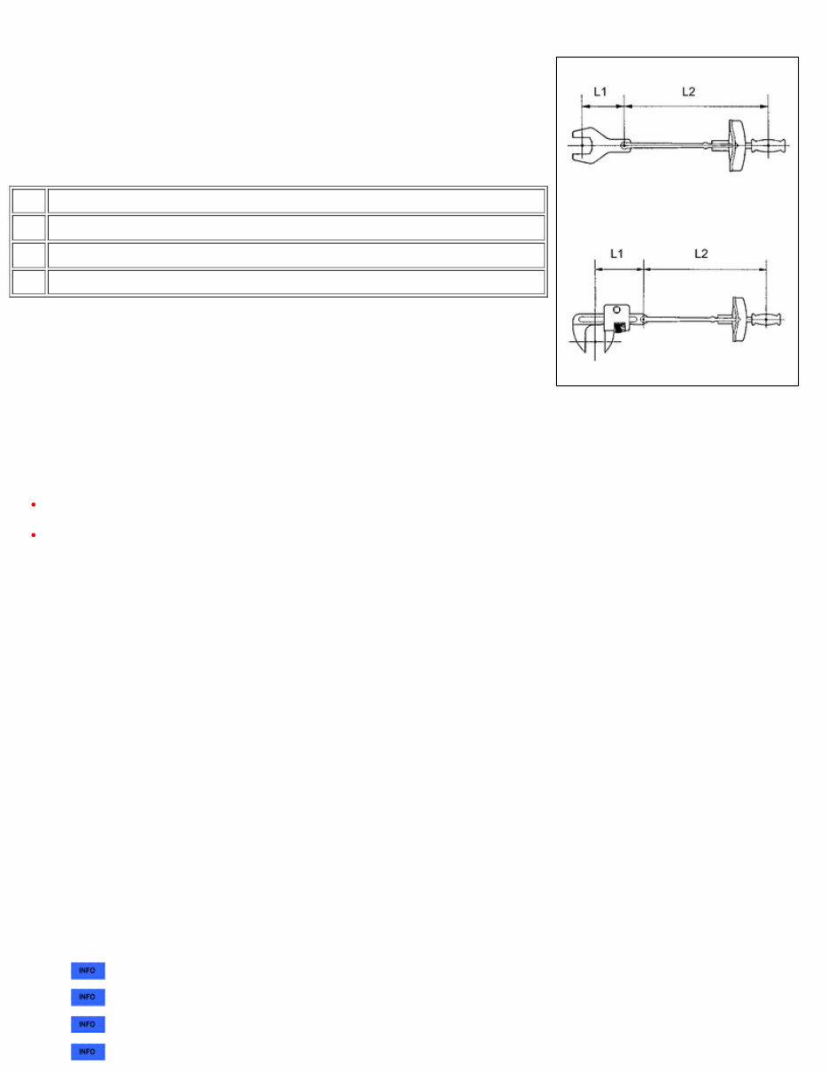
(4) When using a vacuum gauge, never force the hose onto a connector that is too large. If a hose has been stretched, air may leak. Use a step-down adapter if necessary. (j) TORQUE WHEN USING TORQUE WRENCH WITH EXTENSION TOOL (1) Use the formula below to calculate special torque values for situations where SST or an extension tool is combined with the torque wrench. Formula: T' = L2/(L1 + L2) * T T' Reading of torque wrench {N*m (kgf*cm, ft.*lbf)} T Torque {N*m (kgf*cm, ft.*lbf)} L1 Length of SST or extension tool {cm (in.)} L2 Length of torque wrench {cm (in.)} NOTICE: If an extension tool or SST is combined with a torque wrench and the wrench is used to tighten to a torque specification in this manual, the actual torque will be excessive and parts will be damaged. 2. FOR VEHICLES EQUIPPED WITH SRS AIRBAG AND SEAT BELT PRETENSIONER The AVALON is equipped with a Supplemental Restraint System (SRS). CAUTION: Before performing pre-disposal deployment of any SRS component, review and closely follow all applicable environmental and hazardous material regulations. Pre-disposal deployment may be considered hazardous material treatment. Failure to carry out the service operations in the correct sequence could cause the SRS to unexpectedly deploy during servicing and lead to serious injury. Furthermore, if a mistake is made when servicing SRS, it is possible that the SRS may fail to operate properly. Before servicing (including removal or installation of parts, inspection or replacement), be sure to read the following section carefully. (a) GENERAL NOTICE (1) As malfunctions of the SRS are difficult to confirm, the Diagnostic Trouble Codes (DTCs) become the most important source of information when troubleshooting. When troubleshooting the SRS, always check the DTCs before disconnecting the battery. (2) Work must be started at least 90 seconds after the ignition switch is turned off and after the cable is disconnected from the negative (-) battery terminal. The SRS is equipped with a back-up power source. If work is started within 90 seconds after turning the ignition switch off and disconnecting the cable from the negative (-) battery terminal, the SRS may deploy. When the cable is disconnected from the negative (-) battery terminal, clock and audio system memory is erased. Before starting work, make a note of the settings of each memory system. When work is finished, reset the clock and audio system as before. CAUTION: Never use a back-up power source (battery or other) to avoid erasing system memory. The back-up power source may inadvertently power the SRS and cause it to deploy. (3) In minor collisions where the SRS does not deploy, the steering pad, front passenger airbag assembly, driver side knee airbag assembly, front seat side airbag assembly, curtain shield airbag assembly and front seat outer belt assembly should be inspected before further use of the vehicle. for steering pad) for front passenger airbag assembly) for driver side knee airbag assembly) for front seat side airbag assembly)
The 2009 Toyota Avalon Repair Manual is a comprehensive guide designed to provide detailed information on the diagnosis, repair, and maintenance of your vehicle. Suitable for both professional mechanics and DIY enthusiasts, this manual is packed with technical details, diagrams, and step-by-step procedures that cater to a wide range of tasks, from routine maintenance to complex repairs.
Within its pages, you'll find in-depth coverage of various aspects of the Avalon's components, systems, and operations. From troubleshooting and diagnosing issues to replacing and repairing parts, this manual has everything you need to keep your vehicle running smoothly and efficiently.
Whether you're a seasoned mechanic or a DIY enthusiast, this manual is an essential resource that will help you gain a deeper understanding of your vehicle's inner workings. With its clear and concise language, detailed diagrams, and easy-to-follow instructions, it's the perfect companion for anyone looking to perform repairs, maintenance, or upgrades on their 2009 Toyota Avalon.
Comprehensive coverage of the 2009 Toyota Avalon's components, systems, and operations
Technical details, diagrams, and step-by-step procedures for diagnosis, repair, and maintenance
Suitable for both professional mechanics and DIY enthusiasts
Perfect resource for troubleshooting, replacing, and repairing various parts and systems




 Lifetime Access




