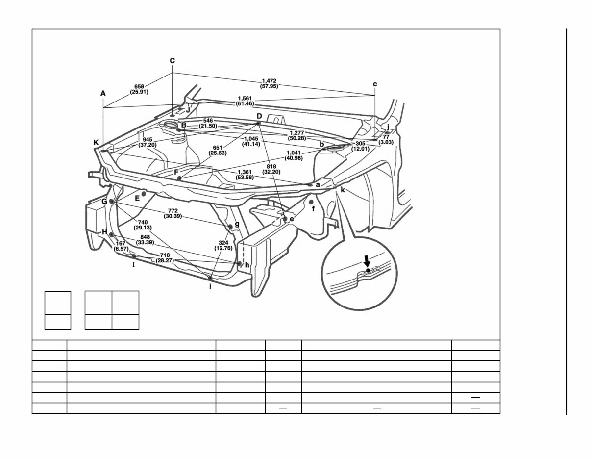
1,524 (60.00) K-k C-K or c-k Vehicle Dimensions Left ↔ Right 666 (26.22) C-K or c-k 1,639 (64.53) mm (in.) (Three-Dimensional Distance) HINT: For symbols, capital letters indicate right side of vehicle, small letters indicate left side of vehicle (Seen from rear.) Hole dia. 7 (0.28) 7 (0.28) 12 (0.47) 8 (0.31) nut Name Front crossmember gusset standard hole Radiator side defector installation hole Front crossmember standard hole Hood hinge installation nut-rear Front apron to cowl side member upper cut-out portion Symbol G, g H, h I, i J, j K, k Hole dia. 6 (0.24) nut 11 (0.43) 6 (0.24) nut 7 (0.28) 13 (0.51) 15 (0.59) Name Front fender installation nut-front Front spring support hole-inner Front fender installation nut-rear Cowl ventilator louver installation hole Front side member standard hole Front side member working hole Symbol A, a B, b C, c D, d E, e F, f BODY DIMENSION DRAWINGS ENGINE COMPARTMENT BODY PANEL REPLACEMENT BP-81 WWW.DARDOOR.COM
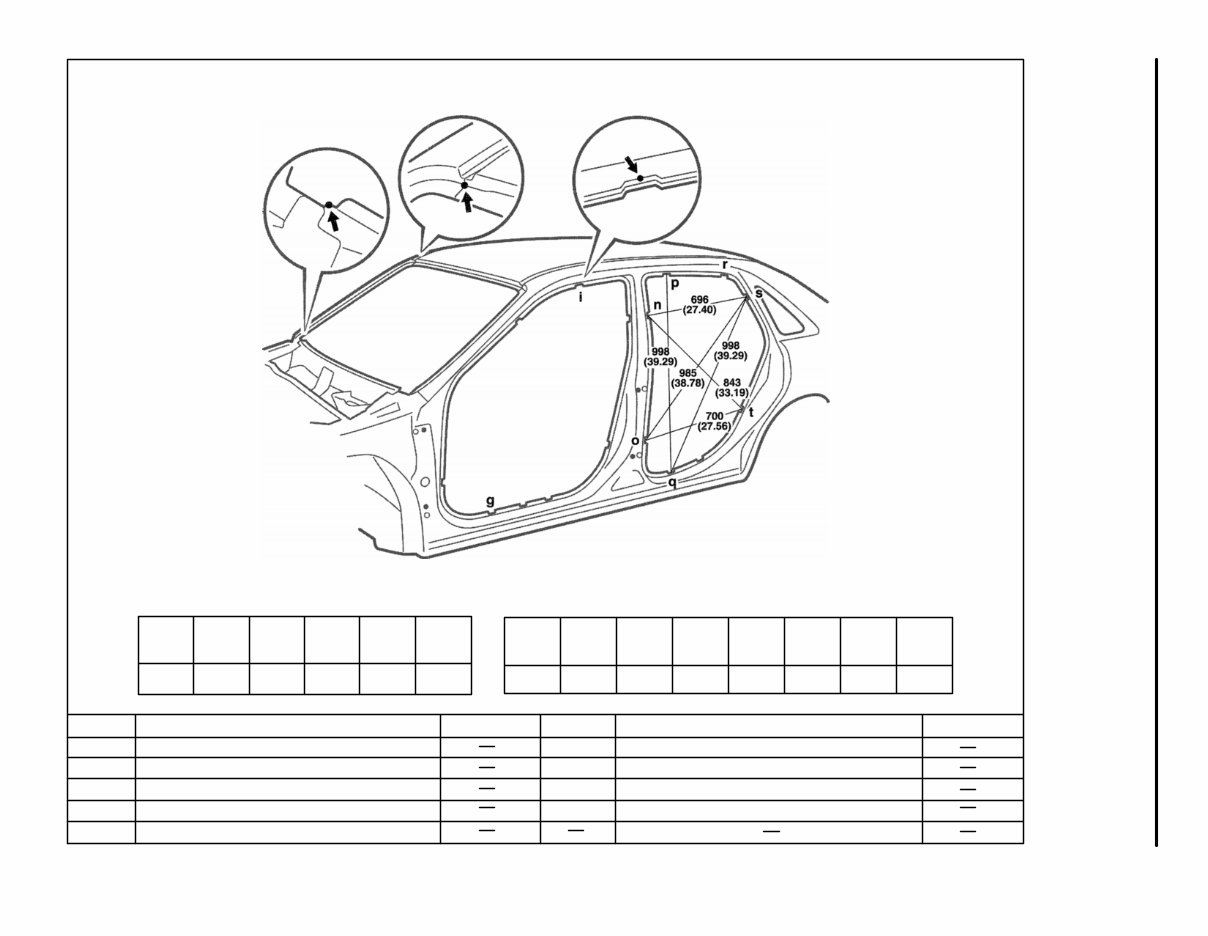
Vehicle Dimensions Left ↔ Right N-n 1,415 (55.71) 1,498 (58.98) O-o 1,242 (48.90) P-p 1,494 (58.82) S-s 1,373 (54.06) T-t 1,491 (58.70) G-q or g-Q 1,831 (72.09) I-p or i-P 1,347 (53.03) I-r or i-R 1,572 (61.89) 1,558 (61.34) N-s or n-S N-t or n-T 1,679 (66.10) 1,650 (64.96) O-t or o-T HINT: For symbols, capital letters indicate right side of vehicle, small letters indicate left side of vehicle (Seen from rear). 1,689 (66.50) P-q or p-Q 1,550 (59.06) S-t or s-T (Three-Dimensional Distance) mm (in.) Q-q Hole dia. Name Rocker panel assembly mark Roof side rail assembly mark Quarter panel assembly mark Quarter panel assembly mark Symbol Q, q R, r S, s T, t Hole dia. Name Rocker panel assembly mark Roof side rail assembly mark Center body pillar assembly mark Center body pillar assembly mark Roof side rail assembly mark Symbol G, g I, i N, n O, o P, p BODY OPENING AREAS (Side View-Rear) BODY PANEL REPLACEMENT BP-83 WWW.DARDOOR.COM
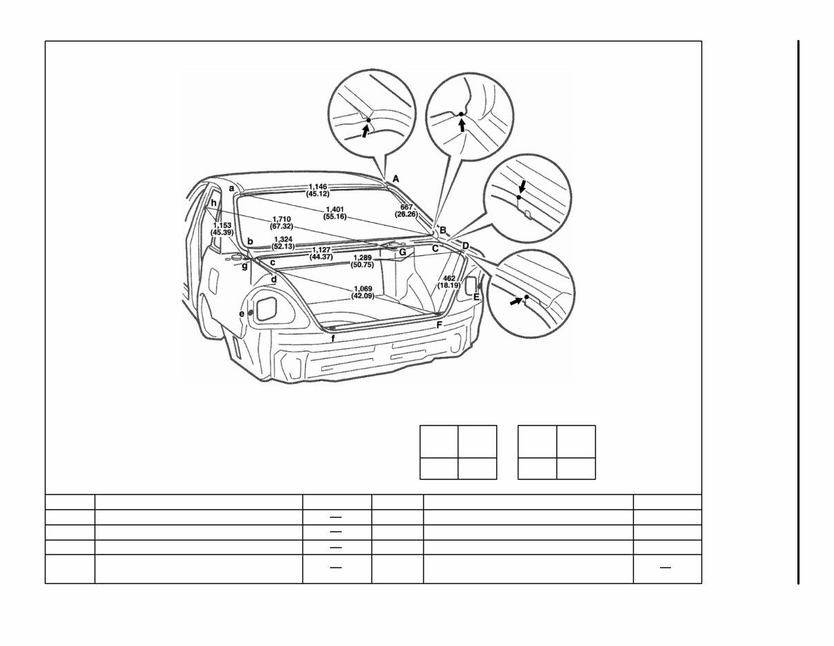
HINT: For symbols, capital letters indicate right side of vehicle, small letters indicate left side of vehicle (Seen from rear). Vehicle Dimensions Left ↔ Right C-c 1,339 (52.72) E-e 1,541 (60.67) C-F or C-f 618 (24.33) C-F or c-f 1,160 (45.67) (Three-Dimensional Distance) mm (in.) Hole dia. 10 (0.39) 7 (0.28) 9.5 (0.374) Name Quarter panel standard hole Rear floor finish plate installation hole Rear spring support hole inner - rear Center body pillar assembly mark Symbol E, e F, f G, g H, h Hole dia. Name Roof panel / Quarter panel adjoining portion Upper back panel / Quarter panel adjoining portion Quarter panel / Upper back panel adjoining portion Luggage compartment opening trough / Quarter panel adjoining portion Symbol A, a B, b C, c D, d BODY OPENING AREAS (Rear View) BODY PANEL REPLACEMENT BP-84 WWW.DARDOOR.COM
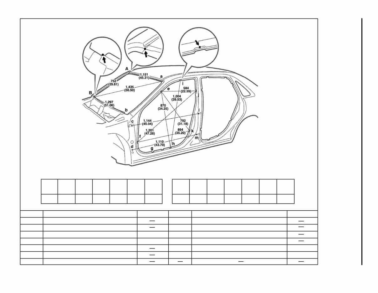
E-e 1,326 (52.20) 1,491 (58.70) F-f Vehicle Dimensions Left ↔ Right 1,491 (58.70) G-g H-h 1,491 (58.70) 1,242 (48.90) I-i J-j 1,402 (55.20) 1,498 (58.98) K-k 1,623 (63.90) E-f or e-F 1,654 (65.12) E-h or e-H E-j or e-J 1,483 (58.39) F-j or f-J 1,880 (74.02) F-k or f-K 1,742 (68.58) H-i or h-I 1,691 (66.57) 1,574 (61.97) J-k or j-K HINT: For symbols, capital letters indicate right side of vehicle, small letters indicate left side of vehicle (Seen from rear). (Three-Dimensional Distance) mm (in.) Hole dia. 15 (0.59) 15 (0.59) Name Rocker panel assembly mark Roof side rail assembly mark Center body pillar assembly mark Center body pillar assembly mark Rear door hinge installation hole-front Rear door hinge installation hole-front Symbol H, h I, i J, j K, k L, l M, m Hole dia. 8 (0.31) nut 8 (0.31) nut Name Roof panel / Front body pillar adjoining portion Cowl panel / Front body pillar adjoining portion Front door hinge installation nut-rear Front door hinge installation nut-upper Front body pillar assembly mark Front body pillar assembly mark Rocker panel assembly mark Symbol A, a B, b C, c D, d E, e F, f G, g BODY OPENING AREAS (Side View-Front) BODY PANEL REPLACEMENT BP-82 WWW.DARDOOR.COM
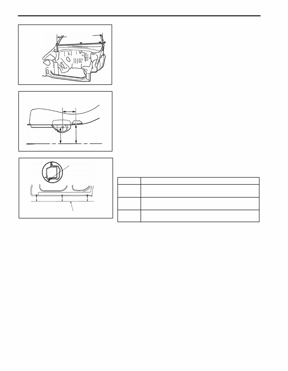
SYMBOL Name 1 The place that was lowered A mm from the under surface of the rocker panel centered on the front jack up point. 2 The place that was lowered B mm from the under surface of the rocker panel centered between 1 and 3. 3 The place that was lowered C mm from the under surface of the rocker panel centered on the rear jack up point. Imaginary Standard Line Vertical distance in lower surface Vertical distance in center Two-dimensional distance Center-to-center Horizontal distance in forward / rearward F10116A Imaginary Standard Line B mm C mm A mm Under Surface of The Rocker Panel F10026A 3 1 2 F10115A Three-dimensional distance Center-to-center straight-line distance GENERAL INFORMATION 1. BASIC DIMENSIONS (a) There are two typed of dimensions in the diagram. (1) (Three-dimensional distance) D Straight-line distance between the centers of two mea- suring points. (2) (Two-dimensional distance) D Horizontal distance in forward/ rearward between the centers of two measuring points. D The height from an imaginary standard line. (b) Incases in which only one dimension is given, left and right are symmetrical. (c) The dimensions in the following drawing indicate actual dis- tance. Therefore, please use the dimensions as a refer- ence. (d) The line that connects the places listed below is the imagi- nary standard line when measuring the height. (The dimen- sions are printed in the text.) BODY PANEL REPLACEMENT BP-79 WWW.DARDOOR.COM
If you are in need of a repair manual for your 2001 Toyota Avalon, look no further. Our accessible repair manual provides comprehensive coverage for the Toyota Avalon, making it an ideal resource for both professional mechanics and DIY enthusiasts.
Gone are the days of purchasing traditional service manuals in book format at a higher cost. Our repair manual offers the same valuable information in a more affordable and convenient digital format.
Whether you require guidance for brake repairs, suspension component replacements, engine troubleshooting, or standard maintenance procedures, this repair manual for the Toyota Avalon has you covered.
With this , you will have access to a wealth of service information, including but not limited to brakes, engine, suspension, steering, drivetrain, electrical systems, heating, and air conditioning. It equips you with the knowledge to address any automotive issue.
By utilizing this 2001 Toyota Avalon repair manual , you can save a substantial amount of money on vehicle maintenance. Rather than relying on costly professional mechanics, empower yourself to tackle repairs with confidence.
Our repair manual is designed for ease of use and is compatible with Windows, Mac computers, smartphones, and tablets, ensuring accessibility across various devices.



 Lifetime Access




