

2025 Toyota 86 Service & Repair Manual
What's Included?
Fast Download Speeds
Online & Offline Access
Access PDF Contents & Bookmarks
Full Search Facility
Print one or all pages of your manual
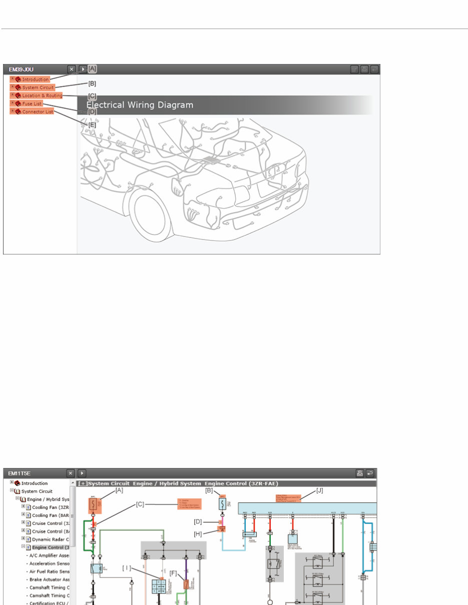
[+]Introduction INTRODUCTION
HOW TO USE THE Electrical Wiring Diagram
Contents of the Electrical Wiring Diagram (EWD)
This document consists of the following sections.
[A]: Introduction
This section explains how to use the Electrical Wiring Diagram.
[B]: System Circuit
The circuit diagrams for the power sources, ground points and on-board systems can be viewed.
(The wiring diagrams cover only the circuit connections between the power source and the electrical components)
[C]: Location & Routing
The locations of the wire harnesses, connectors and ground points can be viewed and the wiring diagrams are sorted into
vehicle specific areas such as the engine compartment, instrument panel, etc. In addition, the relay location sections show the
location of the relays, relay blocks, antennas, and ECUs, as well as the internal circuits.
[D]: Fuse List
The locations of the fuses and fusible links as well as the related systems are sorted into vehicle specific areas and can be
viewed quickly.
[E]: Connector List
The connectors are organized by wire harness, and information for the connectors, ground points, related systems, component
locations, and wire harness routings can be checked quickly.
System Circuit
The system circuit diagrams show electrical connections between the fuses and ground points of each system and are sorted into
system functions. The power source circuit diagrams show the connections between the vehicle power source (on-board battery)
and the fuses, and the ground point circuit diagrams show the connections between the ground points and the components.
[A]: Fuse
The name and capacity of the fuse are shown.
(For locations, refer to the Location & Routing section)
[B]: Power Supply
The ignition switch position that supplies the power to the fuse is indicated.
[C]: Variations
The information is given if connectors, wire connections, or wire colors are different depending on the vehicle model, engine
type, specification, etc.
How to Read Variation Information:
Example 1:(*3, *4 *1) indicated by [b] shown on the wiring diagram above
Read the information shown on the area indicated by [a].
*3:1NR-FE
*4:1NZ-FE
*1:w/ Stop & Start System
A comma (,) between the symbols means “OR” and the absence of a comma (,) denotes “AND” in variation
information, so the example (*3, *4 *1) mentioned above refers to the vehicle model that is equipped with the
1NR-FE "or" 1NZ-FE engine "and" the Stop & Start System.
Example 2: (*4, *2) indicated by [c] shown on the wiring diagram above
Read the information shown on the area indicated by [a].
*4:1NZ-FE
*2:w/o Stop & Start System
As explained above, the variation information (*4, *2) that has a comma between the symbols indicates the
vehicle model that is equipped with the 1NZ-FE engine "or" not equipped with the Stop & Start System.
[D]: Wire Color
The color of the wire is indicated.
Wire Color Codes:
For example, if the wire is indicated by two color codes L and Y in the diagram, it means that yellow lines are on the blue
sheath.
Example: L-Y
L Blue
Y Yellow
Copper wires
B=Black W=White BR=Brown
L=Blue V=Violet SB=Sky Blue
R=Red G=Green LG=Light Green
P=Pink Y=Yellow GR=Gray
O=Orange BE=Beige DG=Dark Gray
Aluminum wires
LA=Lavender
[E]: Junction Block Connector Code
The code refers to the connector that connects to the junction block.
(For connector shapes, refer to the Relay Location under the Location & Routing section)
Junction Block Connector
*a This symbol leads to the internal circuit of the junction block.
*b
The number refers to a serial number assigned to one of the connectors that connect to the
junction block.
*c The alphanumeric code stands for the junction block connector.
*d The number refers to the connector terminal number.
*e The symbol that only shows a number inside stands for a relay block or fuse block.
[F]: Switch
Single switches are shown as a normally open switch.
(For details about the switch on and off conditions, refer to the repair manuals)
[G]: Ground Point Code
The ground point code denotes a ground point.
(For locations, refer to the Location & Routing section)
Ground point code
*a The first letter of the code indicates the alphabetic ID assigned to the wire harness.
*b
The other letter refers to the alphabetic ID assigned to the vehicle ground point.
For example, code “MJ” denotes that wire harness M connects to ground point J.
[H]: Wire-to-Wire Connector Code
The code indicates the connectors that join two wire harnesses together.
(For connector shapes, refer to the Connector List section)
Wire-to-Wire Connector
*a The number refers to the connector terminal number.
*b
The alphabetic code stands for the mated pair of wire harness connectors.
For example, "FH" denotes the connection between the female connector(*1) of wire harness F
and the male connector(*2) of wire harness H.
*1: Connector terminals are female.
*2: Connector terminals are male.
*c
The numeric code refers to the serial number assigned to one of the mated pairs of wire
harness connectors.
*d The symbol indicates the male terminal connector.
[I]: Terminal Number
The number indicates the connector terminal number.
[J]: Connector Codes and Component Name
The name of a system component and the connector codes of the connectors that connect to the system component are
shown together.
(For connector shapes, refer to the Connector List section)
Part connector
*a
The number refers to the connector terminal number.
Letter “G” refers to wire harness G.
The exact name of wire harness G can be found in the Location & Routing section.
*b
The alphabetic code stands for the mated pair of wire harness connectors.
The other code stands for the serial number assigned to one of the connectors of wire harness
G.
*c The code refers to the connector that connects to a component.
*d
The alphabetic code shown inside the parentheses is an ID code that distinguishes between the
connectors if two or more connectors are connected to the same component.
NOTE:
The Electrical Wiring Diagram show the following wire harnesses for reference
purposes only: component wire harnesses that belong to the components, and sub
i h h b id b i i h d
Example: Front Right Door
wire harnesses that serve as a bridge between a main wire harness and a
component. These wire harnesses may not be included in the wiring diagrams or
may be different from those used in the actual vehicles, so refer to the repair
manuals when repairing or inspecting those wire harnesses.
*1 Sub wire harness
*a
Refer to the repair manual for
information on inspection and
repair.
*b Component wire harness
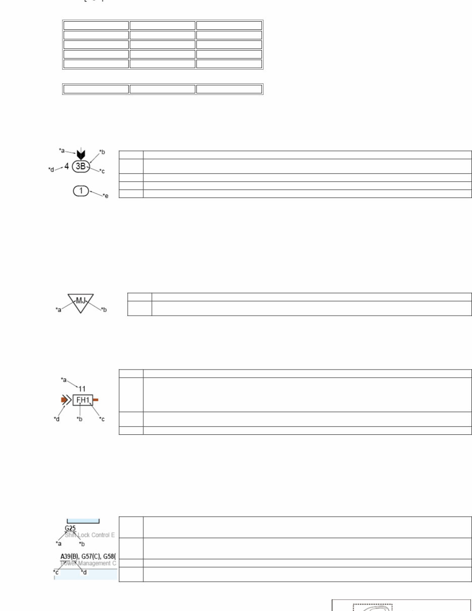
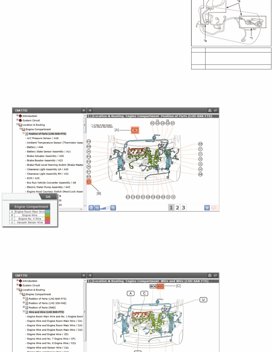
Location & Routing
The locations of the wire harnesses, connectors, components and so on are shown, and the diagrams are sorted into vehicle specific
areas such as the engine compartment, instrument panel, etc. In addition, the Relay Location sections show the locations of the
relays, relay blocks and antennas as well as the internal circuits.
a. Location and Routing Diagram
[A]: Wire Harness Code
The alphabetic ID codes stand for each wire harness, and a wire harness code always comes first when it is combined with
another code in order to represent a connector code of the connector that connects to a component, a wire-to-wire connector
code or a ground point code.
[B]: Connector Code of the Connector Connecting to the Component
The code refers to the connector that connects to the component.
[C]: Wire-to-Wire Connector Code
The code stands for the mated pair of wire harness connectors.
[D]: Ground Point Code
The code stands for a ground point.
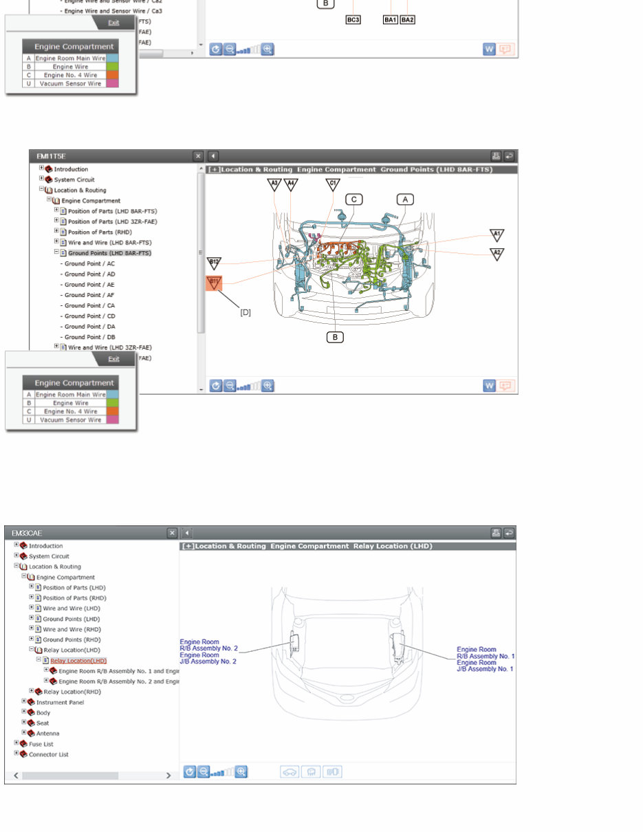
b. Relay Location
The locations of relays, relay blocks (R/B), junction blocks (J/B), and fusible links (F/L) are shown.
c. J/B (Junction Block), R/B (Relay Block), Inner Circuit, Power Distribution Box, and Short Connector
The connectors, relays and fuses that connect to the junction blocks, as well as the internal circuits of the junction blocks are
shown
shown.
[A]: Connector Code
The connector code of the wire harness connector is shown.
[B]: Connector Codes and Terminal Numbers
The connector codes and terminal numbers of the wire harness connectors are shown.
[C]: Connector Shape and Terminal Numbers
The shape of the wire harness connector is shown.
The numbers shown on the connector shape refer to the connector terminal numbers.
[D]: Connector Shape and Terminal Numbers
The shape of the component connector is shown.
The numbers shown on the connector shape refer to the connector terminal numbers.
[E]: Fuse
The name and capacity of each fuse are shown.
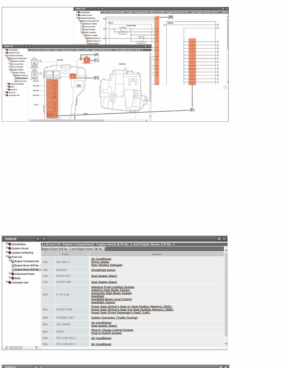
Fuse List
In this section, information for the locations of the fuses and fusible links and the related systems are organized by vehicle specific
area and can be viewed quickly.
Connector List
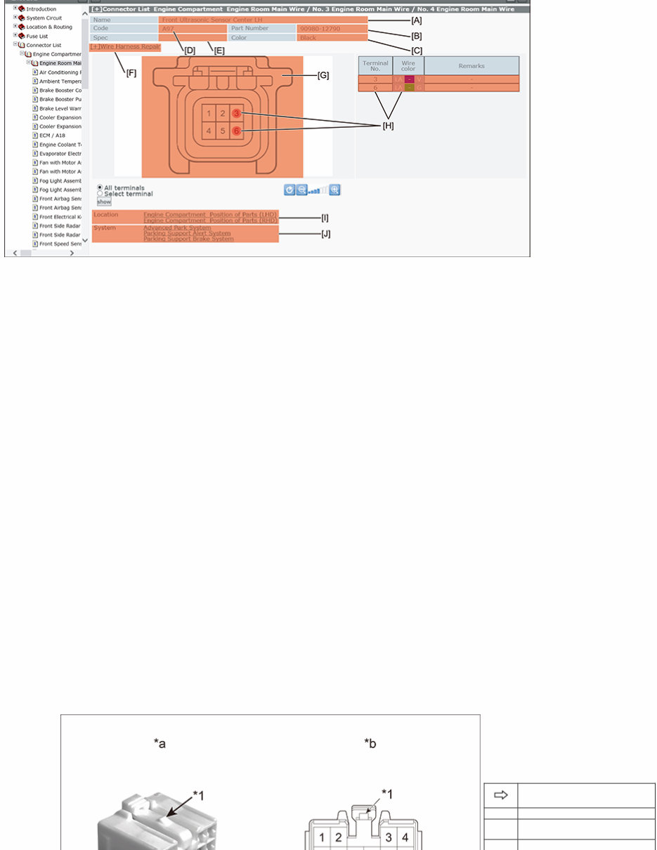
[A]: Name
The name of the component to which the connector is connected is shown.
[B]: Part Number
The Toyota part number assigned to the connector is shown.
[C]: Color
The color of the connector is shown.
[D]: Code
The connector code of the connector is shown.
(The connector codes are common to the system circuit diagrams and location and routing diagrams)
[E]: Spec
Specification differences such as vehicle models, engine types, etc. are shown.
[F]: Wire Harness Repair
Information on the wire harness repair can be accessed.
[G]: Connector Shape and Terminal Numbers
The connector shape and terminal numbers of the wire harness connector are shown.
(The terminal numbers are common to the system circuit diagrams)
[H]: Wire Color
The wire colors can be checked through the tabular list by selecting the terminal numbers shown on the connector picture.
[I]: Location
The location and routing diagrams that include the connector are shown.
[J]: System
The system circuit diagrams that include the connector are shown.
Guide to Read Connector Terminal Numbers
View the connector mating face with the connector housing lock facing top.
Female Connectors
Viewing Direction
*1 Housing Lock
*a
Viewing Direction (Mating
Face)
*b
Connector Terminal
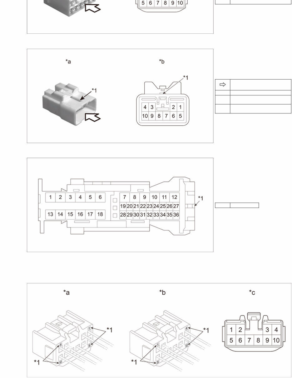
b
Numbers
Male Connectors
Viewing Direction
*1 Housing Lock
*a
Viewing Direction (Mating
Face)
*b
Connector Terminal
Numbers
Exception:
Some connectors need to be viewed with the connector housing lock facing left or right.
*1 Housing Lock
NOTE:
Some of the connector housings are marked with numbers and these markings may be inconsistent with the connector
terminal numbers shown on the wiring diagrams.
In such a case, refer to the terminal numbers shown on the wiring diagrams, not to the connector housing markings, when
conducting repair or inspection.
*1 Marking
*a Housing markings and connector terminal numbers match.
*b Housing markings and connector terminal numbers do not match.
*c Connector Terminal Numbers
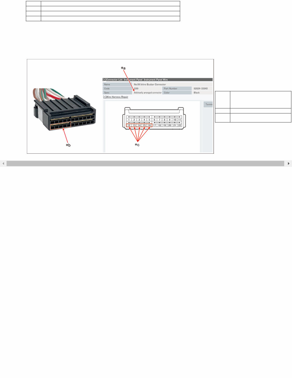
Arbitrarily arranged connectors:
The connecting terminals are arranged arbitrarily in the area, and the terminal numbers and wire colors shown in the circuit
diagram may not match those of the vehicle.
When repairing or inspecting, carefully check the vehicle connector and area in the circuit diagram before proceeding.
NOTE:
Inline Busbar Connector, etc.
*a
Arbitrarily arranged
connectors are clearly
indicated in the Specification
column
*b Same area
*c
Arbitrary arrangement of
terminals in the same area
[+]Introduction GLOSSARY OF TERMS AND SYMBOLS
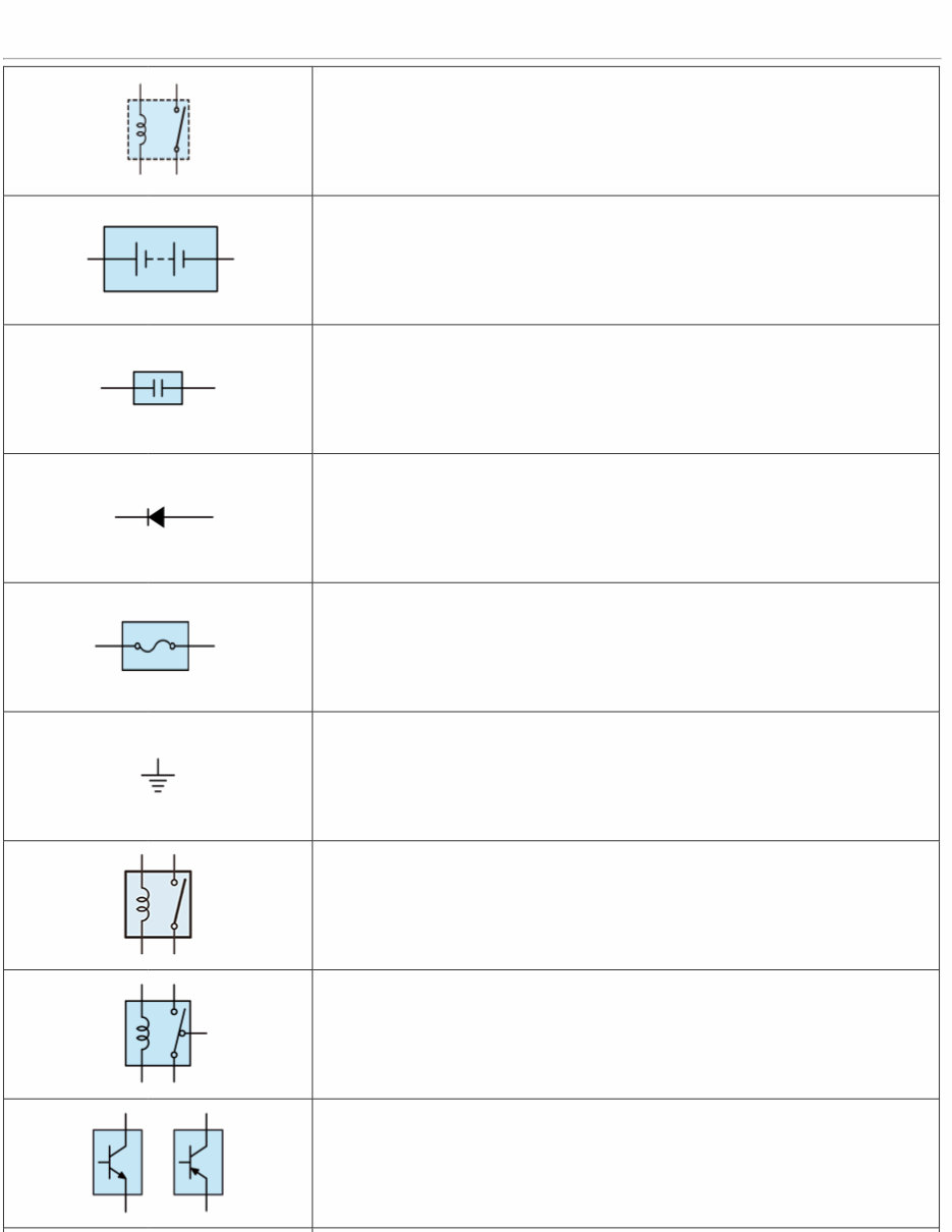
GLOSSARY OF TERMS AND SYMBOLS
Internal configuration of a block component's unit
A symbol expressed with dotted lines stands for a logic circuit provided inside an
internal unit, located in places such as relay blocks (R/B) and junction blocks (J/B).
Since logic circuits cannot be replaced like independent parts, they are not shown in
the external views for that block component's internal unit.
BATTERY
Stores chemical energy and converts it into electrical energy. Provides DC current for
the auto's various electrical circuits.
CAPACITOR (Condenser)
A small holding unit for temporary storage of electrical voltage.
DIODE
A semiconductor which allows current flow in only one direction.
FUSE
A thin metal strip which burns through when too much current flows through it,
thereby stopping current flow and protecting a circuit from damage.
A heavy-gauge wire placed in high amperage circuits which burns through on
overloads, thereby protecting the circuit. The numbers indicate the cross-section
surface area of the wires.
GROUND
The point at which wiring attaches to the Body, thereby providing a return path for
an electrical circuit; without a ground, current cannot flow.
RELAY
Basically, a relay is an electrically operated switch that is normally open.
When an electric current flows through the small coil, a magnetic field is generated,
which opens or closes the connected switch.
RELAY, DOUBLE THROW
A relay which passes current through one set of contacts of the other.
TRANSISTOR
A solidstate device typically used as an electronic relay; stops or passes current
depending on the voltage applied at "base".
You're Reading a Preview
What's Included?
Fast Download Speeds
Online & Offline Access
Access PDF Contents & Bookmarks
Full Search Facility
Print one or all pages of your manual
$57.99
$75.99
Viewed 87 Times Today


Secure transaction
What's Included?
Fast Download Speeds
Online & Offline Access
Access PDF Contents & Bookmarks
Full Search Facility
Print one or all pages of your manual
$57.99
$75.99
The 2025 Toyota 86 Service & Repair Manual is a comprehensive guide designed for both professional mechanics and DIY enthusiasts. This manual provides detailed instructions on troubleshooting, repair, and comprehensive maintenance of your Toyota 86 vehicle. The manual is packed with diagrams, specifications, and step-by-step procedures, giving you the technical knowledge needed to tackle more complex tasks.
- Remedying common issues through troubleshooting and repair procedures
- Explaining routine and advanced maintenance techniques
- Providing detailed visuals and specifications for quick and accurate repairs
- Offering a wealth of information for DIY enthusiasts and professional mechanics alike
This manual is an essential resource for anyone looking to maintain, repair, and customize their Toyota 86. Whether you're a seasoned mechanic or a DIY enthusiast, you'll appreciate the clarity and precision of the instructions provided.


