

1979-1985 Toyota Pickup and 4 Runner Gasoline Service & Repair Manual
What's Included?
Fast Download Speeds
Online & Offline Access
Access PDF Contents & Bookmarks
Full Search Facility
Print one or all pages of your manual
1985 TOYOTA TRUCK &
4-RUNNER Gasoline
REPAIR MANUAL
INTRODUCTION ImI
MAINTENANCE
ENGINE MECHANICAL
EMISSION CONTROL SYSTEM
EFI SYSTEM
FUEL SYSTEM
COOLING SYSTEM ==
LUBRICATION SYSTEM
IGNITION SYSTEM·
STARTING SYSTEM m
CHARGING SYSTEM D=I
CLUTCH 01
MANUAL TRANSMISSION I~~II
AUTOMATIC TRANSMISSION lilI.
TRANSFER mil
PROPELLER SHAFT IAI
FRONT AXLE AND SUSPENSION 1m
REAR AXLE AND SUSPENSION Im1
BRAKE SYSTEM I:JI
STEERING '-1a
BODY ELECTRICAL SYSTEM I:JI
BODY l:l.J
WINCH awl
AIR CONDITIONING SYSTEM 1.:.tI
© 1984 TOYOTA MOTOR CORPORATION
All rights reserved. This book may not be
reproduced or copied, in whole or in part, without
the written permission of Toyota Motor
Corporation.
SERVICE SPECIFICATIONS ..
STANDARD BOLT TIGHTENING TORQUE _
SSTANDSSM _
AUTOM~V5RTf&L~~~\~~181~ ..
ELECTRICAL WIRING DIAGRAMS ..
IN-1
INTRODUCTION
Page
HOW TO USE THIS MANUAL ....................................... IN-2
IDENTIFICATION INFORMATION ................................... IN-4
GENERAL REPAIR INSTRUCTIONS ............................... IN-4 ~
PRECAUTIONS FOR VEHICLES EQUIPPED WITH ~
A CATALYTIC CONVERTER ...................................... IN-7
VEHICLE LIFT AND SUPPORT LOCATIONS ................. IN-8
ABBREVIATIONS USED IN THIS MANUAL................... IN-9
IN-2 INTRODUCTION - How to Use This Manual
260 (19, 25)
750 (54, 74)
Propeller Shaft
I
I
I
L..---
HOW TO USE THIS MANUAL
To assist in finding your way through the manual, the Secti
Title and major heading are given at the top of every page.
An INDEX is provided on the first page of each section to guide
you to the item to be repaired.
At the beginning of each section, PRECAUTIONS are given that
pertain to all repair operations contained in that section. Read
these precautions before starting any repair task.
TROUBLESHOOTING tables are fncluded for each system to help
you diagnose the system problem and find the cause. The repair
for each possible cause is referenced in the remedy column to
quickly lead you to the solution.
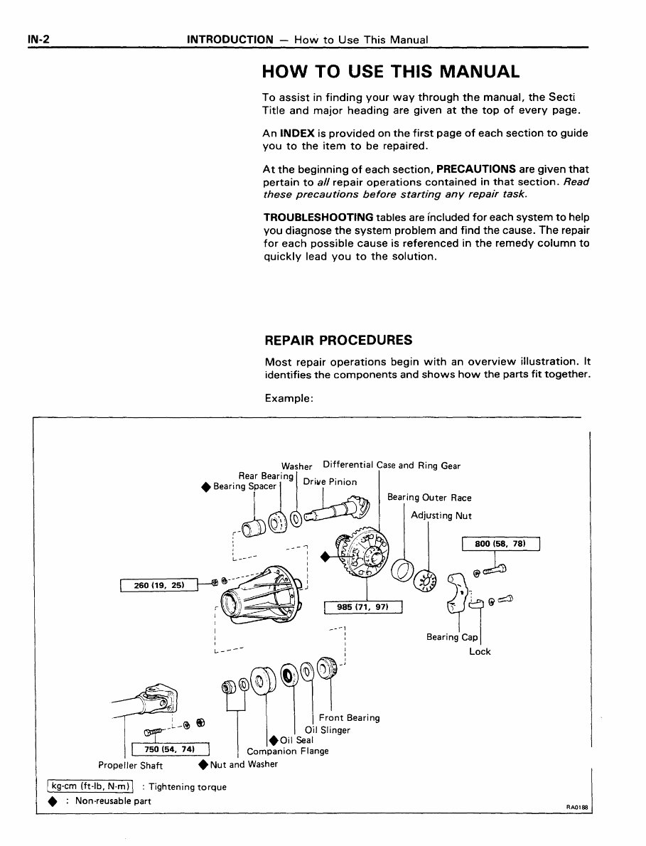
REPAIR PROCEDURES
Most repair operations begin with an overview illustration. It
identifies the components and shows how the parts fit together.
Example:
-- ..,
I
_--1
I
I
I
):)@
~9&~
L..--- I
l))~~-:
Bearing Cap I
Lock
I Front Bearing
Oil Slinger
+Oil Seal
Companion Flange
• Nut and Washer
I kg-cm (ft-Ib, N·m) I : Tightening torque
+ : Non-reusable part
RAOl88
INTRODUCTION - How to Use This Manual IN-3
Photograph or illustration:
what to do and where
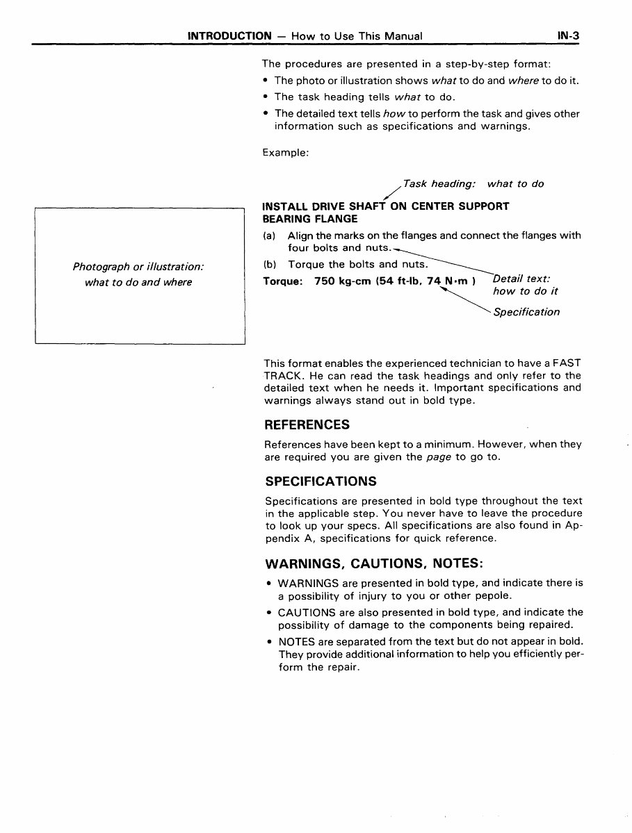
The procedures are presented in a step-by-step format:
• The photo or illustration shows what to do and where to do it.
• The task heading tells what to do.
• The detailed text tells how to perform the task and gives other
information such as specifications and warnings.
Example:
/ Task heading: what to do
INSTALL DRIVE SHAFT ON CENTER SUPPORT
BEARING FLANGE
(a) Align the marks on the flanges and connect the flanges with
four bolts and nuts.~
(b) Torque the bolts and nuts. ________
Torque: 750 kg-em (54 ft-Ib, 74 N.m) Detail text:
~howtOdOit
Specification
This format enables the experienced technician to have a FAST
TRACK. He can read the task headings and only refer to the
detailed text when he needs it. Important specifications and
warnings always stand out in bold type.
REFERENCES
References have been kept to a minimum. However, when they
are required you are given the page to go to.
SPECIFICATIONS
Specifications are presented in bold type throughout the text
in the applicable step. You never have to leave the procedure
to look up your specs. All specifications are also found in Ap-
pendix A, specifications for quick reference.
WARNINGS, CAUTIONS, NOTES:
• WARNINGS are presented in bold type, and indicate there is
a possibility of injury to you or other pepole.
• CAUTIONS are also presented in bold type, and indicate the
possibility of damage to the components being repaired.
• NOTES are separated from the text but do not appear in bold.
They provide additional information to help you efficiently per-
form the repair.

IN-4 INTRODUCTION - Identification Information, General Repair Instructions
INOOOB
IN0007
IDENTIFICATION INFORMATION
VEHICLE IDENTIFICATION NUMBER
The vehicle identification number is stamped on top of the in-
strument panel.
ENGINE SERIAL NUMBER
The engine serial number is stamped on the left side of the
cylinder block.
GENERAL REPAIR INSTRUCTIONS
1. Use fender seat and floor covers to keep the vehicle clean
and prevent damage.
2. During disassembly, keep parts in order to facilitate re-
assembly.
3. Observe the following:
(a) Before performing electrical work, disconnect the
cable from the battery terminal.
(b) If it is necessary to disconnect the battery for inspec-
tion or repair, always disconnect the cable from the
negative (-) terminal which is grounded to the vehi-
cle body.
(c) To prevent damage to the battery terminal post,
loosen the terminal nut and raise the cable straight
up without twisting it or prying it.
(d) Clean the battery terminal posts and cable terminals
with a shop rag. Do not scrape them with a file or
such.
(e) Install the cable terminal to the battery post with the
nut loose, and tighten the nut after installation.
Do not use a hammer or such to tap the terminal on-
to the post.
(f) Be sure the cover for the positive ( + ) terminal is pro-
perly in place.
4. Check hose and wiring connectors to make sure that thr
are secure and correct.

INTRODUCTION - General Repair Instructions IN-5
5. Non-reusable Parts
(a) Always replace cotter pins, gaskets, a-rings and oil
seals etc. with new ones.
(b) Non-reusable parts are indicated in the component
illustrations by the symbol ".".
6. Precoated Parts
Precoated parts are the bolts, nuts, etc. which are coated
with a seal lock adhesive at the factory.
(a) If a precoated part is tightened, loosened or caused
to move in any way, it must be recoated with the
specified adhesive.
Seal Lock Adhesive (b) Recoating of Precoated Parts
84460
(1) Clean off the old adhesive from the bolt, nut or
installation part threads.
(2) Dry with compressed air.
(3) Apply the specified seal lock adhesive to the bolt
or nut threads.
(c) Precoated parts are indicated in the component illus-
trations by the symbol "*".
7. When necessary, use a sealer on gaskets to prevent leaks.
8. Carefully observe all specifications for bolt tightening tor-
ques. Always use a torque wrench.
9. Use of special service tools (SST) and special service
materials (SSM) may be required, depending on the nature
of the repair. Be sure to use SST and SSM where speci-
fied and follow the proper work procedure. A list of SST
and SSM can be found at the back of this manual.
10. When replacing fuses, be sure the new fuse is the correct
amperage rating. DO NOT exceed the fuse amp rating or
use one of a lower rating.
11. Care must be taken when jacking up and supporting the
vehicle. Be sure to lift and support the vehicle at the proper
locations. (See page IN-8)
(a) If the vehicle is to be jacked up only at the front or
rear end, be sure to block the wheels in order to en-
sure safety.
(b) After the vehicle is jacked up, be sure to support it
on stands. It is extremely dangerous to do any work
on the vehicle raised on jack alone, even for a small
job that can be finished quickly.
IN-6 INTRODUCTION - General Repair Instructions
I N0002
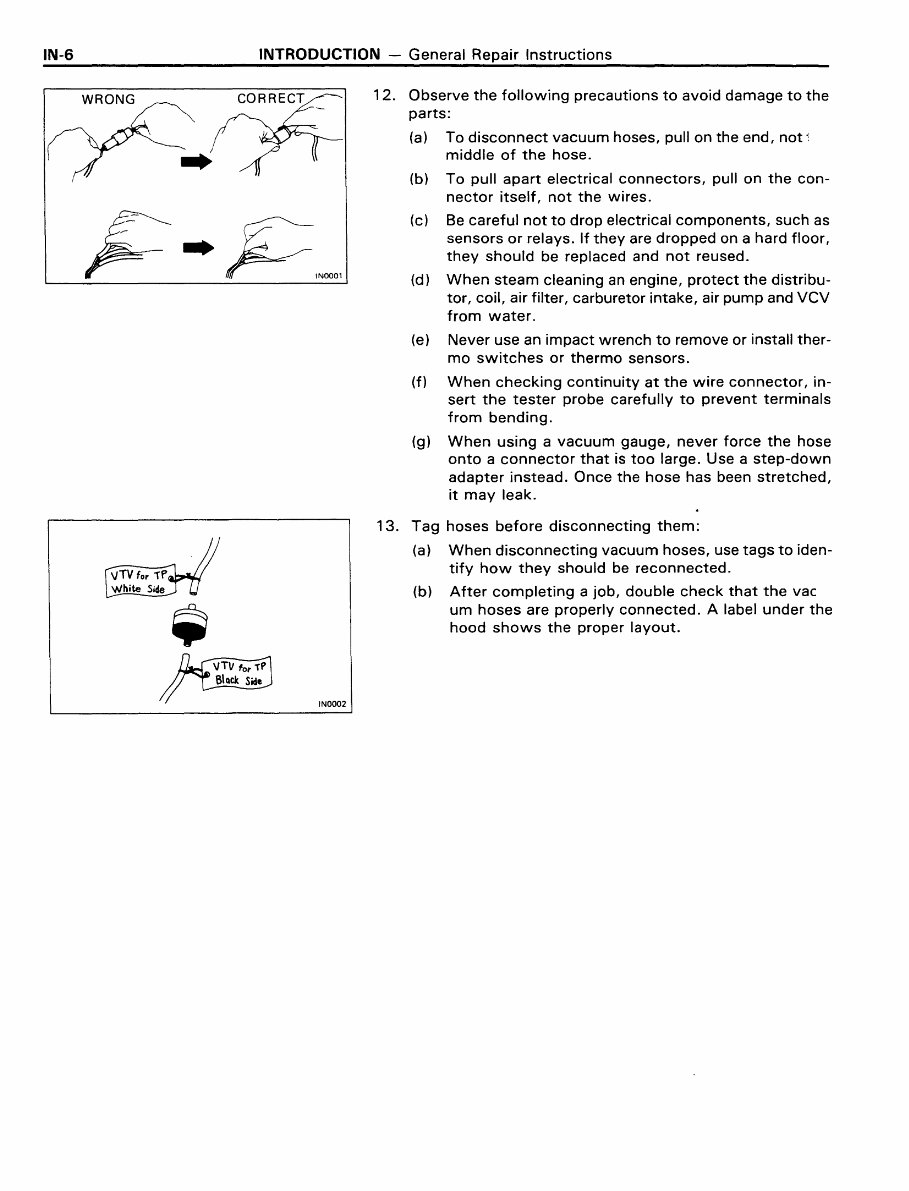
12. Observe the following precautions to avoid damage to the
parts:
(a) To disconnect vacuum hoses, pull on the end, not ~
middle of the hose.
(b) To pull apart electrical connectors, pull on the con-
nector itself, not the wires.
(c) Be careful not to drop electrical components, such as
sensors or relays. If they are dropped on a hard floor,
they should be replaced and not reused.
(d) When steam cleaning an engine, protect the distribu-
tor, coil, air filter, carburetor intake, air pump and VCV
from water.
(e) Never use an impact wrench to remove or install ther-
mo switches or thermo sensors.
(f) When checking continuity at the wire connector, in-
sert the tester probe carefully to prevent terminals
from bending.
(g) When using a vacuum gauge, never force the hose
onto a connector that is too large. Use a step-down
adapter instead. Once the hose has been stretched,
it may leak.
13. Tag hoses before disconnecting them:
(a) When disconnecting vacuum hoses, use tags to iden-
tify how they should be reconnected.
(b) After completing a job, double check that the vac
um hoses are properly connected. A label under the
hood shows the proper layout.

INTRODUCTION - Precautions for Vehicles Equipped with A Catalytic Converter IN-7
PRECAUTIONS FOR VEHICLES EQUIPPED
WITH A CATALYTIC CONVERTER
WARNING: If large amounts of unburned gasoline flow into
the converter, it may overheat and create a fire hazard. To pre-
vent this, observe the following precautions and explain them
to your customer.
1. Use only unleaded gasoline.
2. Avoid prolonged idling.
Avoid running the engine at fast idle speed for more than
10 minutes and at idle speed for more than 20 minutes.
3. Avoid spark jump test.
(a) Spark jump test only when absolutely necessary. Per-
form this test as rapidly as possible.
(b) While testing, never race the engine.
4. Avoid prolonged engine compression measurement.
Engine compression tests must be made as rapidly as
possible.
5. Do not run engine when fuel tank is nearly empty.
This may cause the engine to misfire and create an extra
load on the converter.
6. Avoid coasting with ignition turned off and prolonged
braking.
7. Do not dispose of used catalyst along with parts con-
taminated with gasoline or oil.
IN-8
[4WD]
[2WD]
INTRODUCTION - Vehicle Lift and Support Locations
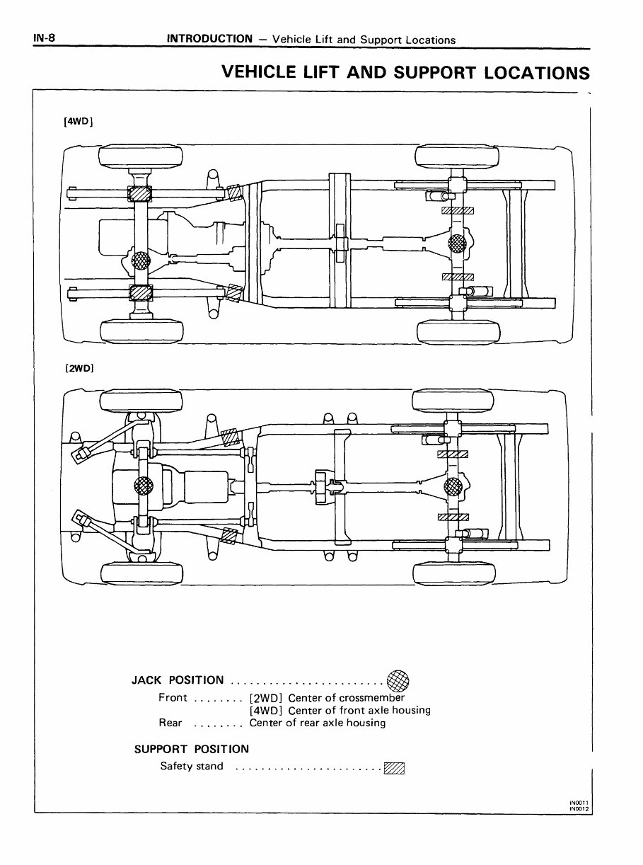
VEHICLE LIFT AND SUPPORT LOCATIONS
JACK POSITION ........................ @
Front .... . . .. [2WD] Center of crossmember
[4WD] Center of front axle housing
Rear ........ Center of rear axle housing
SUPPORT POSITION
Safety stand ....................... ~
INOOll
INOO12
INTRODUCTION - Abbreviations Used in This Manual IN-9
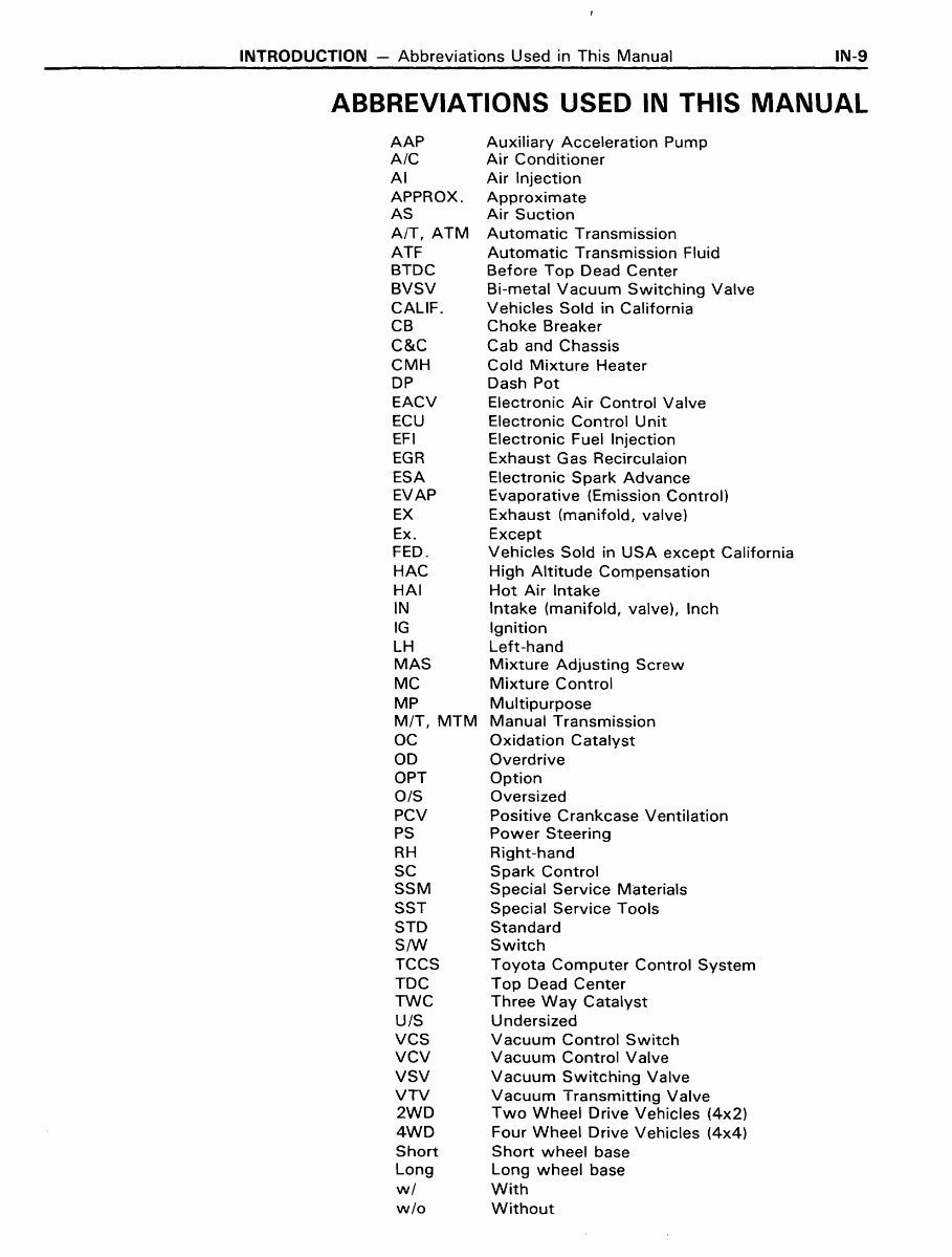
ABBREVIATIONS USED IN THIS MANUAL
AAP
A/C
AI
APPROX.
AS
AIT, ATM
ATF
BTDC
BVSV
CALIF.
CB
C&C
CMH
DP
EACV
ECU
EFI
EGR
ESA
EVAP
EX
Ex.
FED.
HAC
HAl
IN
IG
LH
MAS
MC
MP
MIT, MTM
OC
00
OPT
OIS
PCV
PS
RH
SC
SSM
SST
STD
S/W
TCCS
TDC
TWC
UIS
VCS
VCV
VSV
VTV
2WD
4WD
Short
Long
wi
wlo
Auxiliary Acceleration Pump
Air Conditioner
Air Injection
Approximate
Air Suction
Automatic Transmission
Automatic Transmission Fluid
Before Top Dead Center
Bi-metal Vacuum Switching Valve
Vehicles Sold in California
Choke Breaker
Cab and Chassis
Cold Mixture Heater
Dash Pot
Electronic Air Control Valve
Electronic Control Unit
Electronic Fuel Injection
Exhaust Gas Recirculaion
Electronic Spark Advance
Evaporative (Emission Control)
Exhaust (manifold, valve)
Except
Vehicles Sold in USA except California
High Altitude Compensation
Hot Air Intake
Intake (manifold, valve), Inch
Ignition
Left-hand
Mixture Adjusting Screw
Mixture Control
Multipurpose
Manual Transmission
Oxidation Catalyst
Overdrive
Option
Oversized
Positive Crankcase Ventilation
Power Steering
Right-hand
Spark Control
Special Service Materials
Special Service Tools
Standard
Switch
Toyota Computer Control System
Top Dead Center
Three Way Catalyst
Undersized
Vacuum Control Switch
Vacuum Control Valve
Vacuum Switching Valve
Vacuum Transmitting Valve
Two Wheel Drive Vehicles (4x2)
Four Wheel Drive Vehicles (4x4)
Short wheel base
Long wheel base
With
Without
You're Reading a Preview
What's Included?
Fast Download Speeds
Online & Offline Access
Access PDF Contents & Bookmarks
Full Search Facility
Print one or all pages of your manual
$32.99
$42.99
Viewed 75 Times Today


Secure transaction
What's Included?
Fast Download Speeds
Online & Offline Access
Access PDF Contents & Bookmarks
Full Search Facility
Print one or all pages of your manual
$32.99
$42.99
The Toyota Pickup and 4 Runner Gasoline Workshop Manual is a comprehensive guide for all Toyota Pickup and 4 Runner models. It provides detailed instructions and diagrams for maintenance, repair, and troubleshooting of these vehicles. Whether you own a 1979, 1980, 1981, 1982, 1983, 1984, or 1985 model, this manual has got you covered.
Key features of the Toyota Pickup and 4 Runner Gasoline Workshop Manual include:
- Step-by-step procedures for engine, transmission, brakes, suspension, electrical, and other systems
- Exploded diagrams and illustrations to assist in understanding complex components
- Troubleshooting tips to diagnose issues and find solutions
- Comprehensive coverage of all gasoline engine models for the specified years
With this workshop manual, you can save time and money by performing various maintenance and repair tasks on your Toyota Pickup or 4 Runner. It is a must-have resource for DIY enthusiasts and professional mechanics alike.


