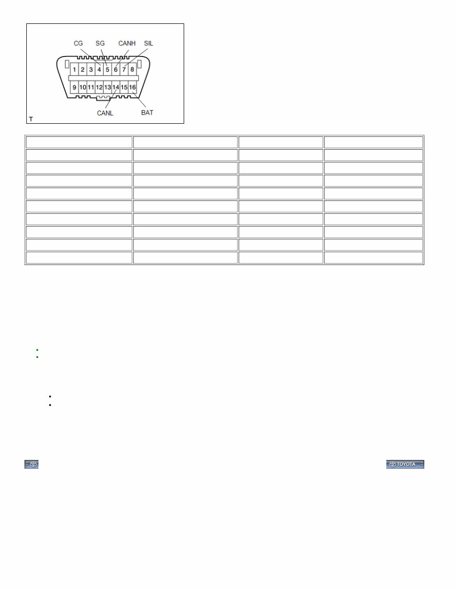
Last Modified: 03-17-2020 6.10:8.0.50 Doc ID: RM100000000RTB0 Model Year Start: 2016 Model: 4Runner Prod Date Range: [08/2015 - ] Title: INTRODUCTION: HOW TO TROUBLESHOOT ECU CONTROLLED SYSTEMS: GENERAL INFORMATION; 2016 - 2020 MY 4Runner [08/2015 - ] GENERAL INFORMATION A large number of ECU controlled systems are used in the 4RUNNER. In general, ECU controlled systems are considered to be very intricate, requiring a high level of technical knowledge to troubleshoot. However, most problem checking procedures only involve inspecting the ECU controlled system's circuits one by one. An adequate understanding of the system and a basic knowledge of electricity is enough to perform effective troubleshooting, accurate diagnoses and necessary repairs. 1. TROUBLESHOOTING PROCEDURES The troubleshooting procedures consist of diagnosis procedures for when a DTC is stored and diagnosis procedures for when no DTC is stored. The basic idea is explained in the following table. PROCEDURE TYPE DETAILS TROUBLESHOOTING METHOD DTC Based Diagnosis The diagnosis procedure is based on the DTC that is stored. The malfunctioning part is identified based on the DTC detection conditions using a process of elimination. The possible trouble areas are eliminated one-by-one by use of the Techstream and inspection of related parts. Symptom Based Diagnosis (No DTCs stored) The diagnosis procedure is based on problem symptoms. The malfunctioning part is identified based on the problem symptoms using a process of elimination. The possible trouble areas are eliminated one-by-one by use of the Techstream and inspection of related parts. Vehicle systems are complex and use many ECUs that are difficult to inspect independently. Therefore, a process of elimination is used, where components that can be inspected individually are inspected, and if no problems are found in these components, the related ECU is identified as the problem and replaced. It is extremely important to ask the customer about the environment and the conditions present when the problem occurred (Customer Problem Analysis). This makes it possible to simulate the conditions and confirm the symptom. If the symptom cannot be confirmed or the DTC does not recur, the malfunctioning part may not be identified using the troubleshooting procedure, and the ECU for the related system may be replaced even though it is not defective. If this happens, the original problem will not be solved. In order to prevent endless expansion of troubleshooting procedures, the troubleshooting procedures are written with the assumption that multiple malfunctions do not occur simultaneously for a single problem symptom. To identify the malfunctioning part, troubleshooting procedures narrow down the target by separating components, ECUs and wire harnesses during the inspection. If the wire harness is identified as the cause of the problem, it is necessary to inspect not only the connections to components and ECUs but also all of the wire harness connectors between the component and the ECU. 2. DESCRIPTION System data and the Diagnostic Trouble Codes (DTCs) can be read from the Data Link Connector 3 (DLC3) of the vehicle. When the system seems to be malfunctioning, use the Techstream to check for a malfunction and perform repairs. 3. DATA LINK CONNECTOR 3 (DLC3) (a) The vehicle ECU uses the ISO 15765-4 communication protocol. The terminal arrangement of the DLC3 complies with SAE J1962 and matches the ISO 15765-4 format.
TERMINAL NO. (SYMBOL) TERMINAL DESCRIPTION CONDITION SPECIFIED CONDITION 7 (SIL) - 5 (SG) Bus "+" line During transmission Pulse generation 4 (CG) - Body ground Chassis ground Always Below 1 Ω 5 (SG) - Body ground Signal ground Always Below 1 Ω 16 (BAT) - Body ground Battery positive Always 11 to 14 V 6 (CANH) - 14 (CANL) CAN bus line Ignition switch off* 54 to 69 Ω 6 (CANH) - 4 (CG) HIGH-level CAN bus line Ignition switch off* 200 Ω or higher 14 (CANL) - 4 (CG) LOW-level CAN bus line Ignition switch off* 200 Ω or higher 6 (CANH) - 16 (BAT) HIGH-level CAN bus line Ignition switch off* 6 kΩ or higher 14 (CANL) - 16 (BAT) LOW-level CAN bus line Ignition switch off* 6 kΩ or higher NOTICE: *: Before measuring the resistance, leave the vehicle as is for at least 1 minute and do not operate the ignition switch, any other switches, or the doors. If the result is not as specified, the DLC3 may have a malfunction. Repair or replace the harness and connector. (b) Connect the cable of the Techstream to the DLC3, turn the ignition switch on and attempt to use the tester. If the display indicates that a communication error has occurred, there is a problem either with the vehicle or with the tester. HINT: If communication is normal when the tester is connected to another vehicle, inspect the DLC3 of the original vehicle. If communication is still not possible when the tester is connected to another vehicle, the problem may be in the tester itself. Consult the Service Department listed in the tester's instruction manual. FOR USING TECHSTREAM Before using the Techstream, read the tester operator's manual thoroughly. If the tester cannot communicate with the ECU controlled systems when connected to the DLC3 with the ignition switch in the on position and the tester turned on, there is a problem on the vehicle side or tester side. a. If communication is possible when the tester is connected to another vehicle, inspect the diagnosis data link line (bus (+) line), CANH and CANL lines, and the power circuits for the vehicle ECUs. b. If communication is still not possible when the tester is connected to another vehicle, the problem is probably in the tester itself. Perform the Self Test procedure outlined in the tester operator's manual.
Last Modified: 03-17-2020 6.10:8.0.50 Doc ID: RM100000000RTB2 Model Year Start: 2016 Model: 4Runner Prod Date Range: [08/2015 - 08/2019] Title: INTRODUCTION: HOW TO TROUBLESHOOT ECU CONTROLLED SYSTEMS: HOW TO PROCEED WITH TROUBLESHOOTING; 2016 - 2019 MY 4Runner [08/2015 - 08/2019] HOW TO PROCEED WITH TROUBLESHOOTING 1. OPERATION FLOW HINT: Perform troubleshooting in accordance with the procedures below. The following is an outline of basic troubleshooting procedures. Confirm the troubleshooting procedures for the circuit you are working on before beginning troubleshooting. 2. 1.VEHICLE BROUGHT TO WORKSHOP PROCEED TO NEXT 3. 2.CUSTOMER PROBLEM ANALYSIS (a) Ask the customer about the conditions and environment when the problem occurred. PROCEED TO NEXT 4. 3.INSPECT BATTERY VOLTAGE Standard voltage: 11 to 14 V If the voltage is below 11 V, recharge or replace the battery before proceeding. PROCEED TO NEXT 5. 4.SYMPTOM CONFIRMATION AND DTC (INCLUDING FREEZE FRAME DATA) CHECK (a) Visually check the wire harnesses, connectors and fuses for open and short circuits. (b) Warm up the engine to the normal operating temperature. (c) Confirm the problem symptoms and conditions, and check for DTCs. Result RESULT PROCEED TO DTC is output Go to step 5 DTC is not output Go to step 6 6. 5.DTC CHART (a) Check the results obtained in the DTC check. Then find the output DTC in the DTC chart. Look at the "Trouble Area" column for a list of potentially malfunctioning circuits and/or parts. PROCEED TO Go to step 7 7. 6.PROBLEM SYMPTOMS TABLE (a) Check the results obtained in the symptom confirmation. Then find the problem symptoms in the problem symptoms table. Look at the "Suspected Area" column for a list of potentially malfunctioning circuits and/or parts. PROCEED TO
PROCEED TO NEXT 8. 7.CIRCUIT INSPECTION OR PARTS INSPECTION (a) Confirm the malfunctioning circuit or part. PROCEED TO NEXT 9. 8.ADJUST, REPAIR OR REPLACE (a) Adjust, repair or replace the malfunctioning circuit or parts. PROCEED TO NEXT 10. 9.CONFIRMATION TEST (a) After the adjustment, repairs or replacement, confirm that the malfunction no longer exists. If the malfunction does not reoccur, perform a confirmation test under the same conditions and in the same environment as when the malfunction occurred the first time. PROCEED TO END 11. CUSTOMER PROBLEM ANALYSIS HINT: In troubleshooting, confirm that the problem symptoms have been accurately identified. Preconceptions should be discarded in order to make an accurate judgment. To clearly understand what the problem symptoms are, it is extremely important to ask the customer about the problem and the conditions at the time the malfunction occurred. Gather as much information as possible for reference. Past problems that seem unrelated may also help in some cases. The following 5 questions are important points in the problem analysis: What Vehicle model, system name When Date, time, occurrence frequency Where Road conditions Under what conditions? Running conditions, driving conditions, weather conditions How did it happen? Problem symptoms 12. SYMPTOM CONFIRMATION AND DIAGNOSTIC TROUBLE CODE HINT: The diagnostic system in the 4RUNNER has various functions. The first function is the Diagnostic Trouble Code (DTC) check. A DTC is a code stored in the ECU memory whenever a malfunction in the signal circuits to the ECU occurs. In a DTC check, a previous malfunction DTC can be checked by a technician during troubleshooting. Another function is the Input Signal Check, which checks if the signals from various switches are sent to the ECU correctly. By using these functions, the problem areas can be narrowed down and troubleshooting is more effective. Diagnostic functions are incorporated in the following systems in the 4RUNNER. SYSTEM DTC CHECK (NORMAL MODE) DTC CHECK (CHECK MODE) FREEZE FRAME DATA SENSOR CHECK/TEST MODE (INPUT SIGNAL CHECK) DATA LIST ACTIVE TEST CUSTOMIZE PARAMETER 1GR-FE SFI System ○ ○ ○ - ○ ○ - Cruise Control System ○ - - - ○ ○ - A750E Automatic Transmission System ○ ○ ○ - ○ ○ -
SYSTEM DTC CHECK (NORMAL MODE) DTC CHECK (CHECK MODE) FREEZE FRAME DATA SENSOR CHECK/TEST MODE (INPUT SIGNAL CHECK) DATA LIST ACTIVE TEST CUSTOMIZE PARAMETER A750F Automatic Transmission System ○ ○ ○ - ○ ○ - Kinetic Dynamic Suspension System ○ - - - ○ ○ - Tire Pressure Warning System ○ - - - ○ ○ - Vehicle Stability Control System (for Hydraulic Brake Booster) ○ - ○ ○ ○ ○ - Vehicle Stability Control System (for Vacuum Brake Booster) ○ - ○ ○ ○ ○ - Power Steering System ○ - - - ○ - - Steering Lock System ○ - - - ○ ○ - Audio and Visual System ○ - - - ○ - - Navigation System ○ - - - ○ - - Intuitive Parking Assist System - - - - - - - Rear View Monitor System (for Radio and Display Type) ○ - - - - - - Rear View Monitor System (for Navigation Receiver Type) ○ - - - - - - Garage Door Opener System - - - - - - - Safety Connect System ○ - - - ○ ○ ○ LIN Communication System ○ - - - ○ - - CAN Communication System ○ - - - - - - Power Door Lock Control System - - - - ○ ○ ○ Wireless Door Lock Control System (w/ Smart Key System) ○ - - - ○ ○ ○ Wireless Door Lock Control System (w/o Smart Key System) ○ - - - ○ ○ ○ Key Reminder Warning System - - - - ○ - - Smart Key System (for Start Function) ○ - - - ○ ○ - Smart Key System (for Entry Function) ○ - - - ○ ○ ○ Engine Immobiliser System (w/ Smart Key System) ○ - - - ○ ○ - Engine Immobiliser System (w/o Smart Key System) ○ - - - ○ ○ - Theft Deterrent System - - - - ○ ○ - Lighting System (for Interior) - - - - ○ ○ ○ Meter / Gauge System ○ - - - ○ ○ ○ Clock System - - - - - - - Airbag System ○ ○ - - ○ - - Occupant Classification System ○ - - - ○ - - Front Power Seat Control System - - - - - - - Seat Heater System - - - - - - - Seat Belt Warning System - - - - ○ ○ ○ Air Conditioning System (for Automatic Air Conditioning System) ○ - - - ○ ○ ○
SYSTEM DTC CHECK (NORMAL MODE) DTC CHECK (CHECK MODE) FREEZE FRAME DATA SENSOR CHECK/TEST MODE (INPUT SIGNAL CHECK) DATA LIST ACTIVE TEST CUSTOMIZE PARAMETER Air Conditioning System (for Manual Air Conditioning System) ○ - - - ○ ○ - Power Window Control System ○ - - - ○ ○ ○ Window Defogger System - - - - - ○ - Sliding Roof System ○ - - - ○ ○ ○ Power Mirror Control System - - - - - - - Wiper and Washer System - - - - - ○ ○ Lighting System (for Exterior) ○ - - - ○ ○ ○ Horn System - - - - - - - Automatic Running Board System ○ - - - - ○ - In the DTC check, it is very important to determine whether the problem indicated by the DTC is either: 1) still occurring; or 2) occurred in the past but has since returned to normal. In addition, the DTC should be compared to the problem symptom to see if they are related. For this reason, DTCs should be checked before and after confirmation of symptoms (i.e., whether or not problem symptoms exist) to determine current system conditions, as shown in the flowchart below. Never skip the DTC check. Failing to check DTCs may, depending on the case, result in unnecessary troubleshooting for systems operating normally or lead to repairs not related to the problem. Follow the procedures listed in the flowchart in the correct order. The following flowchart shows how to proceed with troubleshooting using the DTC check. Directions from the flowchart will indicate how to proceed either to DTC troubleshooting or to the troubleshooting of each problem symptom. 13. 1.DTC CHECK PROCEED TO NEXT 14. 2.MAKE A NOTE OF DTC DISPLAYED AND THEN CLEAR MEMORY PROCEED TO NEXT 15. 3.SYMPTOM CONFIRMATION Result RESULT PROCEED TO No symptoms exist Go to step 4 Symptoms exist Go to step 5 16. 4.SIMULATION TEST USING SYMPTOM SIMULATION METHODS PROCEED TO NEXT 17. 5.DTC CHECK Result RESULT PROCEED TO DTC is not output GO TO STEP 6 DTC is output TROUBLESHOOTING OF PROBLEM INDICATED BY DTC 18. 6.SYMPTOM CONFIRMATION Result
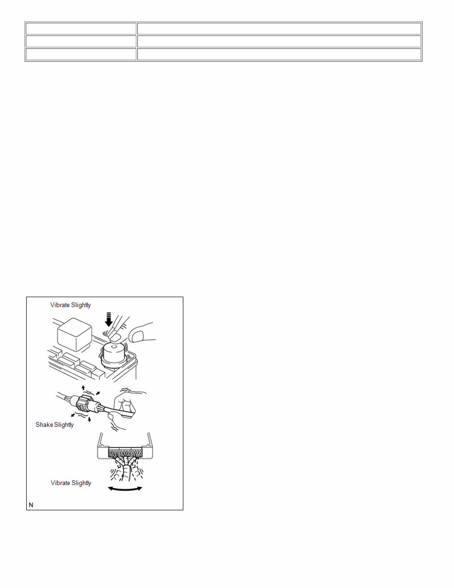
RESULT PROCEED TO Symptoms exist TROUBLESHOOTING OF EACH PROBLEM SYMPTOM No symptoms exist SYSTEM NORMAL If a DTC was displayed in the initial DTC check, the problem may have occurred in a wire harness or connector in that circuit in the past. Check the wire harness and connectors. The problem is still occurring in a place other than the diagnostic circuit (the DTC displayed first is either for a past problem or a secondary problem). 19. SYMPTOM SIMULATION HINT: The most difficult case in troubleshooting is when no problem symptoms occur. In such a case, a thorough problem analysis must be carried out. A simulation of the same or similar conditions and environment in which the problem occurred in the customer vehicle should be carried out. No matter how much skill or experience a technician has, troubleshooting without confirming the problem symptoms will lead to important repairs being overlooked and mistakes or delays. For example: With a problem that only occurs when the engine is cold or as a result of vibration caused by the road during driving, the problem can never be determined if the symptoms are being checked on a stationary vehicle or on a vehicle with a warmed-up engine. Vibration, heat or water penetration (moisture) is difficult to reproduce. The symptom simulation tests below are effective substitutes for the conditions and can be applied on a stationary vehicle. Important points in the symptom simulation test: In the symptom simulation test, the problem symptoms as well as the problem area or parts must be confirmed. First, narrow down the possible problem circuits according to the symptoms. Then, connect the tester and carry out the symptom simulation test, judging whether the circuit being tested is defective or normal. Also, confirm the problem symptoms at the same time. Refer to the problem symptoms table for each system to narrow down the possible causes. To reproduce DTCs, it is necessary to satisfy the respective DTC detection conditions. (a) VIBRATION METHOD: When a malfunction seems to occur as a result of vibration. (1) PART AND SENSOR Apply slight vibration with a finger to the part of the sensor suspected to be the cause of the problem, and check whether or not the malfunction occurs. NOTICE:
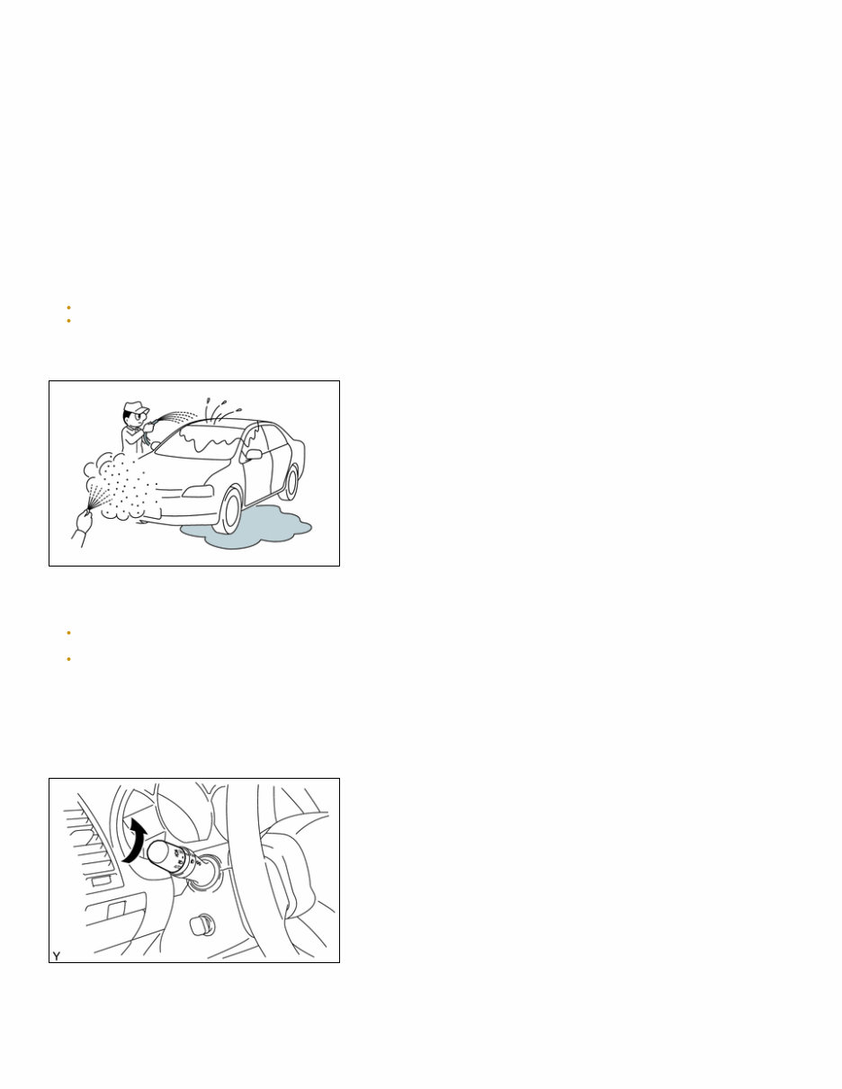
Applying strong vibration to relays may open them. (2) CONNECTORS Slightly shake the connector vertically and horizontally. (3) WIRE HARNESS Slightly shake the wire harness vertically and horizontally. HINT: The connector joint and fulcrum of the vibration are the major areas that should be checked thoroughly. (b) HEAT METHOD: When a malfunction seems to occur when the area in question is heated. (1) Heat the component that is the possible cause of the malfunction with a hair dryer or similar device. Check if the malfunction occurs. NOTICE: Do not heat to more than 60°C (140°F). Exceeding this temperature may damage components. Do not apply heat directly to the parts in the ECU. (c) WATER SPRINKLING METHOD: When a malfunction seems to occur on a rainy day or in high-humidity. (1) Sprinkle water onto the vehicle and check if the malfunction occurs. NOTICE: Never sprinkle water directly into the engine compartment. Indirectly change the temperature and humidity by spraying water onto the front of the radiator. Never apply water directly onto the electronic components. HINT: If the vehicle has or had a water leakage problem, the leakage may have damaged the ECU or connections. Look for evidence of corrosion or short circuits. Proceed with caution during water tests. (d) HIGH ELECTRICAL LOAD METHOD: When a malfunction seems to occur when the electrical load is excessive. (1) Turn on the heater blower, headlights, rear window defogger and all other electrical loads. Check if the malfunction reoccurs. 20. DIAGNOSTIC TROUBLE CODE CHART
Look for output Diagnostic Trouble Codes (DTCs) (from the DTC checks) in the Diagnostic Trouble Code Chart of the appropriate section. Use the chart to determine the trouble area and the proper inspection procedure. A description of each column of the chart is below. ITEM DESCRIPTION DTC No. Indicates the diagnostic trouble code. Detection Item Indicates the system or details of the problem. Trouble Area Indicates the suspected areas of the problem. See Page Indicates the page where the inspection procedures for each circuit can be found, or where there are instructions for checks and repairs. 21. PROBLEM SYMPTOMS TABLE When a "Normal" code is output during a DTC check but the problem is still occurring, use the Problem Symptoms Table. The suspected areas (circuits or parts) for each problem symptom are in the table. The suspected areas are listed in order of probability. A description of each column of the chart is below. HINT: In some cases, the problem is not detected by the diagnostic system even though a problem symptom is present. It is possible that the problem is occurring outside the detection range of the diagnostic system, or that the problem is occurring in a completely different system. ITEM DESCRIPTION Symptom - Suspected Area Indicates the circuit or part which needs to be checked. See Page Indicates the page where the flowchart for each circuit is located. 22. CIRCUIT INSPECTION A description of the main areas of each circuit inspection is below. ITEM DESCRIPTION Circuit Description The major role and operation of the circuit and its component parts are explained. DTC No., DTC Detection Condition, Trouble Area Indicates the diagnostic trouble codes, diagnostic trouble code detection conditions, and trouble areas of a problem. Wiring Diagram This shows a wiring diagram of the circuit. Use this diagram together with an ELECTRICAL WIRING DIAGRAM to thoroughly understand the circuit. Inspection Procedures Use the inspection procedures to determine if the circuit is normal or abnormal. If abnormal, use the inspection procedures to determine whether the problem is located in the sensors, actuators, wire harnesses or ECU. Inspection Procedure Connector Illustrations Connector being checked is connected: Connections of tester are indicated by (+) or (-) after the terminal name. Connector being checked is disconnected: For illustrations of inspections between a connector and body ground, information about the body ground is not shown in the illustration.
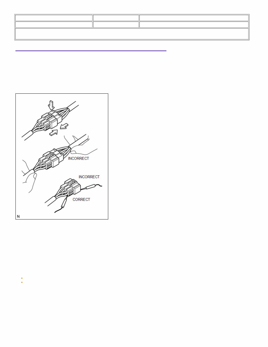
Last Modified: 03-17-2020 6.10:8.0.50 Doc ID: RM100000000RTB1 Model Year Start: 2016 Model: 4Runner Prod Date Range: [08/2015 - ] Title: INTRODUCTION: HOW TO TROUBLESHOOT ECU CONTROLLED SYSTEMS: ELECTRONIC CIRCUIT INSPECTION PROCEDURE; 2016 - 2020 MY 4Runner [08/2015 - ] ELECTRONIC CIRCUIT INSPECTION PROCEDURE 1. BASIC INSPECTION (a) WHEN MEASURING RESISTANCE OF ELECTRONIC PARTS (1) Unless otherwise stated, all resistance measurements should be made at an ambient temperature of 20°C (68°F). Resistance measurements may be inaccurate if measured at high temperatures, i.e. immediately after the vehicle has been running. Measurements should be made after the engine has cooled down. (b) HANDLING CONNECTORS (1) When disconnecting a connector, first squeeze the mating halves tightly together to release the lock, and then press the lock claw and separate the connector. (2) When disconnecting a connector, do not pull on the harnesses. Grasp the connector directly and separate it. (3) Before connecting a connector, check that there are no deformed, damaged, loose or missing terminals. (4) When connecting a connector, press firmly until it locks with a "click" sound. (5) If checking a connector with a TOYOTA electrical tester, check the connector from the backside (harness side) using a mini test lead. NOTICE: As a waterproof connector cannot be checked from the backside, check it by connecting a sub-harness. Do not damage the terminals by moving the inserted tester needle. (c) CHECKING CONNECTORS
Upgrade your maintenance game with the comprehensive 2016-2019 Toyota 4Runner Service & Repair Manual. This PDF manual is your go-to resource for ensuring your 4Runner is running smoothly and efficiently.
With detailed instructions and diagrams, this manual covers everything from routine maintenance tasks to complex repairs. Whether you're a seasoned mechanic or a DIY enthusiast, you'll find the information you need to keep your 4Runner in top condition.
Gain insights into the inner workings of your vehicle with step-by-step guides for engine repairs, electrical systems, brakes, suspension, and more. Troubleshoot issues with confidence using the troubleshooting tips and diagnostic procedures outlined in the manual.
Stay ahead of the curve with the latest service recommendations and technical specifications straight from the manufacturer. This manual is designed to help you tackle any maintenance or repair task efficiently, saving you time and money in the long run.
Don't let unexpected issues derail your adventures. Equip yourself with the 2016 Toyota 4Runner Service & Repair Manual and take control of your vehicle's maintenance needs.