

2005 Toyota 4Runner Service & Repair Manual
What's Included?
Fast Download Speeds
Online & Offline Access
Access PDF Contents & Bookmarks
Full Search Facility
Print one or all pages of your manual
0108G−08
N17080
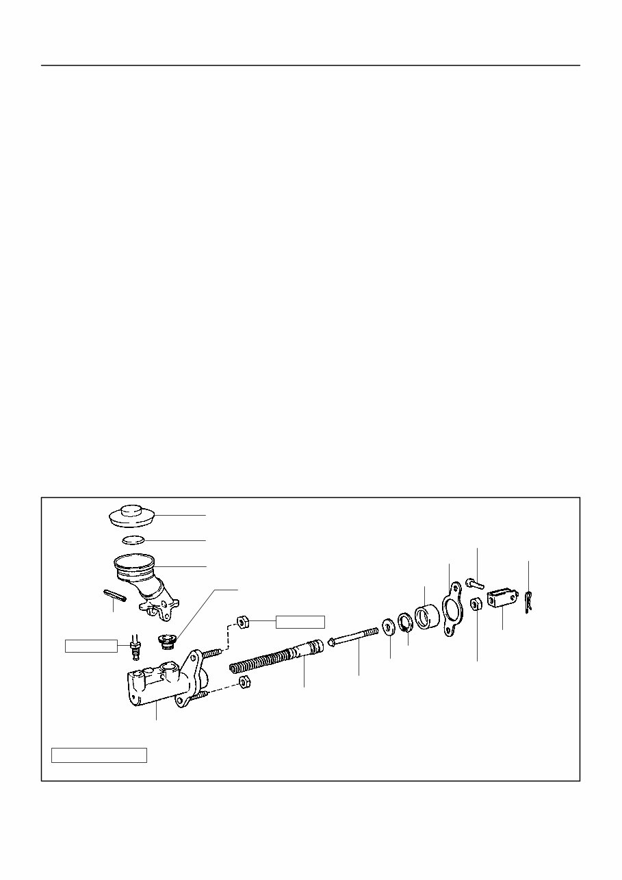
Filler Cap
Float
Reservoir Tank
z Grommet
Clip
Slotted Spring Pin
: Specified torque
z Non−reusable part
Cylinder
Piston
Push Rod
Washer
Snap Ring
Boot
z Gasket
Lock Nut
Clevis Pin
Clevis
N·m (kgf·cm, ft·lbf)
12 (120, 9)
15 (155, 11)
− INTRODUCTION HOW TO USE THIS MANUAL
01−1
1 Author: Date:
2005 4RUNNER REPAIR MANUAL (RM1165U)
HOW TO USE THIS MANUAL
GENERAL INFORMATION
1. GENERAL DESCRIPTION
(a) This manual is written in accordance with SAE J2008.
(b) Repair operations can be separated into 3 main processes:
1. Diagnosis
2. Removing/Installing, Replacing, Disassembling/Reassembling, Checking and Adjusting
3. Final Inspection
(c) This manual explains the ”Diagnosis” (found in the ”Diagnostics” section) and ”Removing and Instal-
ling, Replacing, Disassembling, Installing and Checking, and Adjusting”. ”Final Inspection” is omitted.
(d) The following essential operations are not written in this manual. However, these operations must be
performed in actual situations.
(1) Operations with a jack or lift
(2) Cleaning of a removed part when necessary
(3) Visual check
2. INDEX
(a) An alphabetical INDEX section is provided at the end of the book as a reference to help you find the
item to be repaired.
3. PREPARATION
(a) Use of Special Service Tools (SST) and Special Service Materials (SSM) may be required, depending
on the repair situation. Be sure to use SST and SSM when they are required and follow the working
procedure properly. A list of SST and SSM is in the Preparation section of this manual.
4. REPAIR PROCEDURES
(a) A component illustration is placed under the title where necessary.
(b) Non−reusable parts, grease application areas, precoated parts and torque specifications are noted
in the component illustrations.
Example:
Illustration:
what to do and where
Component part No.
Detailed text: how to perform task
Task heading: what to do
Set part No
Illustration:
what to do and where
Component part No.
Explanation test: how to perform task
Task heading: what to do
Set part No
Illustration:
what to do and where
Component part No.
Task heading: what to do
Set part No.
D26745
01−2
− INTRODUCTION HOW TO USE THIS MANUAL
2 Author: Date:
2005 4RUNNER REPAIR MANUAL (RM1165U)
(c) Torque specifications, grease application areas, and non−reusable parts are emphasized in the proce-
dures.
NOTICE:
There are cases where such information can only be explained by using an illustration. In these
cases, all the information such as torque, oil, etc. are described in the illustration.
(d) The installation procedures are the removal procedures in reverse order. However, only installation
procedures requiring additional information are included.
(e) Only items with key points are described in the text. What to do and other details are placed in illustra-
tions next to the text. Both the text and illustrations are accompanied by standard values and notices.
(f) Illustrations of similar vehicle models are sometimes used. In those cases, specific details may be dif-
ferent from the actual vehicle.
(g) Procedures are presented in a step−by−step format:
(1) The illustration shows what to do and where to do it.
(2) The task heading tells what to do.
(3) The explanation text tells how to perform the task. It also has information such as specifications
and warnings.
Example:
HINT:
This format provides an experienced technician with a FAST TRACK to the necessary information. The task
headings are easy to read and the text below the task heading provides detailed information. Important spec-
ifications and warnings are always written in bold type.
5. SERVICE SPECIFICATIONS
(a) SPECIFICATIONS are presented in bold−faced text throughout the manual. The specifications are
also found in the Service Specifications section for quick reference.
6. TERMS DEFINITION
CAUTION Possibility of injury to you or other people.
NOTICE Possibility of damage to the components being repaired.
HINT Provides additional information to help you perform repairs.

− INTRODUCTION HOW TO USE THIS MANUAL
01−3
3 Author: Date:
2005 4RUNNER REPAIR MANUAL (RM1165U)
7. SI UNIT
(a) The units used in this manual comply with the SI UNIT (International System of Units) standard. Units
from the metric system and the English system are also provided.
Example:
Torque: 30 N⋅m (310 kgf⋅cm, 22 ft⋅lbf)

01044−24
01−24
− INTRODUCTION HOW TO TROUBLESHOOT ECU CONTROLLED
SYSTEMS
24 Author: Date:
2005 4RUNNER REPAIR MANUAL (RM1165U)
HOW TO TROUBLESHOOT ECU CONTROLLED SYSTEMS
GENERAL INFORMATION
A large number of ECU controlled systems are used in the 4RUNNER. In general, ECU controlled systems
are considered to be very intricate, requiring a high level of technical knowledge to troubleshoot. However,
most problem checking procedures only involve inspecting the ECU controlled system’s circuits one by one.
An adequate understanding of the system and a basic knowledge of electricity is enough to perform effective
troubleshooting, accurate diagnoses and necessary repairs. Detailed information and troubleshooting pro-
cedures on major ECU controlled systems in this vehicle are outlined below:
System Page
1. SFI System (1GR−FE) 05−1
2. SFI System (2UZ−FE) 05−394
3. Tire Pressure Warning System 05−858
4. Rear Air Suspension System 05−919
5. ABS with EBD & BA & TRAC & VSC System 05−994
6. Electronically Controlled Automatic Transmission [ECT]
((A750E/A750F)(1GR−FE))
05−1199
7. Electronically Controlled Automatic Transmission [ECT]
((A750E/A750F)(2UZ−FE))
05−1352
8. Air Conditioning System 05−1501
9. Supplemental Restraint System 05−1597
10.Lighting System 05−1926
11.Wiper & Washer System 05−1968
12.Audio System 05−1988
13.Navigation System 05−2061
14.Back Monitor System 05−2202
15.Combination Meter 05−2213
16.Power Window Control System 05−2260
17.Back Door Power Window Control System 05−2287
18.Power Door Lock Control System 05−2307
19.Back Door Closer System 05−2332
20.Wireless Door Lock Control System 05−2349
21.Key Reminder Warning System 05−2373
22.Engine Immobilizer System 05−2387
23.Theft Deterrent System 05−2414
24.Multiplex Communication System 05−2435
25.Can Communication System 05−2456
26.Cruise Control System 05−2514

− INTRODUCTION HOW TO TROUBLESHOOT ECU CONTROLLED
SYSTEMS
01−25
25 Author: Date:
2005 4RUNNER REPAIR MANUAL (RM1165U)
FOR USING OBD II SCAN TOOL OR HAND−HELD TESTER
S Before using the scan tool or tester, the scan tool’s instruction book or tester’s operator manual should
be read thoroughly.
S If the scan tool or tester cannot communicate with the ECU controlled systems when you have con-
nected the cable of the tester to the DLC3 with the ignition switch and tester turned ON, there is a prob-
lem on the vehicle side or tester side.
(1) If communication is normal when the tester is connected to another vehicle, inspect the diagnosis
data link line (Busęline) or ECU power circuit of the vehicle.
(2) If communication is still impossible when the tester is connected to another vehicle, the problem
is probably in the tester itself. So perform the Self Test procedures outlined in the Tester Opera-
tor’s Manual.
03123−04
03−8
− SERVICE SPECIFICATIONS FUEL
139 Author: Date:
2005 4RUNNER REPAIR MANUAL (RM1165U)
TORQUE SPECIFICATION
1GR−FE:
Part Tightened N⋅m kgf⋅cm ft⋅lbf
Fuel delivery pipe sub−assy x Intake manifold 15 153 11
Intake air surge tank x Intake manifold 28 286 21
Intake air surge tank x Throttle body bracket 21 214 16
Intake air surge tank x Surge tank stay No. 1 21 214 16
Intake air surge tank x Surge tank stay No. 2 21 214 16
Fuel pressure regulator assy x Fuel delivery pipe sub−assy 9.0 92 80 in.⋅lbf
Fuel tank x Body 40 408 30
Fuel tank protector sub−assy No.1 x Body 20 204 15
2UZ−FE:
Part Tightened N⋅m kgf⋅cm ft⋅lbf
Delivery pipe x Intake manifold 21 214 16
Delivery pipe No.2 x Intake manifold 21 214 16
Fuel hose x Delivery pipe 39 400 29
Vacuum switching valve assy No.1 x Intake manifold 18 185 13
Fuel pipe sub−assy No.3 x Intake manifold 7.5 80 66 in.⋅lbf
Fuel pipe sub−assy No.1 x Delivery pipe 39 400 29
Throttle body cover sub−assy x Intake manifold 7.5 80 66 in.⋅lbf
Fuel tank x Body 40 408 30
Fuel tank protector sub−assy No.1 x Body 20 204 15
0312D−02
03−24
− SERVICE SPECIFICATIONS COOLING
155 Author: Date:
2005 4RUNNER REPAIR MANUAL (RM1165U)
TORQUE SPECIFICATION
1GR−FE:
Part Tightened N⋅m kgf⋅cm ft⋅lbf
Cylinder block water drain cock plug x Cylinder block water drain cock 13 130 9
Water pump assy x Timing chain or belt cover sub−assy
10 mm (0.39 in.) head
12 mm (0.47 in.) head
9.0
23
92
235
80 in.⋅lbf
17
Idler pulley sub−assy No. 2 x Timing chain or belt cover sub−assy 39 398 29
Water inlet x Timing chain or belt cover sub−assy 9.0 92 80 in.⋅lbf
Fan shroud x Radiator 5.0 51 44 in.⋅lbf
Fan w/ fluid coupling x Water pump 21 214 15
V−bank cover x Intake air surge tank 7.5 76 66 in.⋅lbf
Engine under cover sub−assy No. 1 x Frame assy 29 296 21
Water inlet w/ thermostat x Water inlet 9.0 92 80 in.⋅lbf
Radiator x Radiator support 18 184 13
2UZ−FE:
Part Tightened N⋅m kgf⋅cm ft⋅lbf
Drain plug x Union on cylinder block 13 130 9
Fan x Fluid coupling 5.5 55 47 in.⋅lbf
Water pump x Cylinder block Bolt
Stud bolt and nut
21
18
215
185
16
13
Water inlet housing x Water pump 18 185 13
Water inlet x Water inlet housing 19 195 14
Radiator x Radiator support 18 184 13
Fan shroud x Radiator 5.0 51 44 in.⋅lbf
Radiator reserve tank x Fan shroud 5.0 51 44 in.⋅lbf
0312E−03
− SERVICE SPECIFICATIONS LUBRICATION
03−25
156 Author: Date:
2005 4RUNNER REPAIR MANUAL (RM1165U)
LUBRICATION
SERVICE DATA
1GR−FE:
Oil pressure
at idle speed
at 3,000 rpm
29 kPa (0.3 kgf/cm
2
, 4.2 psi) or more
294 − 588 kPa (3.0 − 6.0 kgf/cm
2
, 43 − 85 psi)
Oil pump
Tip clearance Standard
Maximum
Side clearance Standard
Maximum
Body clearance Standard
Maximum
0.06 − 0.16 mm (0.0024 − 0.0063 in.)
0.16 mm (0.0063 in.)
0.03 − 0.09 mm (0.0012 − 0.0035 in.)
0.09 mm (0.0035 in.)
0.250 − 0.325 mm (0.0098 − 0.0128 in.)
0.325 mm (0.0128 in.)
2UZ−FE:
Oil pressure
at idle speed
at 3,000 rpm
29 kPa (0.3 kgf/cm
2
, 4.2 psi) or more
294 − 588 kPa (3.0 − 6.0 kgf/cm
2
, 43 − 85 psi)
Oil pump
Tip clearance Standard
Maximum
Side clearance Standard
Maximum
Body clearance Standard
Maximum
0.060 to 0.180 mm (0.0024 to 0.0071 in.)
0.18 mm (0.0071 in.)
0.030 to 0.090 mm (0.0012 to 0.0035 in.)
0.09 mm (0.0035 in.)
0.250 to 0.325 mm (0.0098 to 0.0128 in.)
0.325 mm (0.0128 in.)
0312F−04
03−26
− SERVICE SPECIFICATIONS LUBRICATION
157 Author: Date:
2005 4RUNNER REPAIR MANUAL (RM1165U)
TORQUE SPECIFICATION
1GR−FE:
Part Tightened N⋅m kgf⋅cm ft⋅lbf
Oil pressure switch x Oil filter bracket sub−assy 15 152 11
Oil pan drain plug x Oil pan sub−assy No.2 40 408 30
Timing chain cover sub−assy x Cylinder head and block 23 235 17
Oil filter bracket sub−assy x Timing chain cover sub−assy 19 194 14
Camshaft timing oil control valve assy x Timing chain cover sub−assy 9.0 92 80 in.⋅lbf
Ignition coil assy x Cylinder head cover sub−assy 10 102 7
V−bank cover x Intake air surge tank 7.5 76 66 in.⋅lbf
Oil pump relief valve x Oil pump cover 49 500 36
Oil pump cover x Timing chain or belt cover sub−assy 9.0 92 80 in.⋅lbf
Oil pipe x Timing chain or belt cover and oil pump cover 9.0 92 80 in.⋅lbf
Oil cooler assy x Oil filter bracket sub−assy 68 693 50
2UZ−FE:
Part Tightened N⋅m kgf⋅cm ft⋅lbf
No. 2 oil pan x Drain plug 39 398 29
Oil pump x Cylinder block 14 mm head
Others
31
16
311
160
23
11
Oil pump body cover x Oil pump body 10 105 7
Oil pump relief valve x Oil pump body 49 500 36
Oil cooler x Oil filter bracket 69 700 51
0312G−06
− SERVICE SPECIFICATIONS IGNITION
03−27
158 Author: Date:
2005 4RUNNER REPAIR MANUAL (RM1165U)
IGNITION
SERVICE DATA
1GR−FE:
Spark plug
Recommended spark plug DENSO made
NGK made
Electrode gap
Maximum electrode gap
K20HR−U11
LFR6C−11
1.0 to 1.1 mm (0.039 to 0.043 in.)
1.41 mm (0.056 in.)
VVT sensor
Voltage VVT1+ − VVT1−
VVT2+ − VVT2−
3.375 to 4.950V (Hi), 0.450 to 1.375V (Lo)
3.375 to 4.950V (Hi), 0.450 to 1.375V (Lo)
Crankshaft position sensor
Resistance at Cold
at Hot
1,630 to 2,740 Ω
2,065 to 3,225 Ω
2UZ−FE:
Spark plug
Recommended spark plug DENSO made
NGK made
Electrode gap
Maximum electrode gap
Correct insulation resistance
SK20R11
1FR6A11
1.0 to 1.1 mm (0.039 − 0.043 in.)
1.3 mm (0.051 in.)
10 MΩ or more
VVT sensor
Resistance at Cold
at Hot
835 to 1,400 Ω
1,060 to 1,645 Ω
Crankshaft position sensor
Resistance at Cold
at Hot
1,630 to 2,740 Ω
2,065 to 3,225 Ω
You're Reading a Preview
What's Included?
Fast Download Speeds
Online & Offline Access
Access PDF Contents & Bookmarks
Full Search Facility
Print one or all pages of your manual
$31.99
$41.99
Viewed 32 Times Today


Secure transaction
What's Included?
Fast Download Speeds
Online & Offline Access
Access PDF Contents & Bookmarks
Full Search Facility
Print one or all pages of your manual
$31.99
$41.99
This digital Toyota 4Runner repair manual provides comprehensive and detailed information for maintaining and repairing your vehicle. Suitable for both professional mechanics and DIY enthusiasts, it covers a wide range of topics, including troubleshooting, servicing, and major repairs. The manual is organized for easy reference, with clear diagrams, specifications, and step-by-step procedures to help you understand the inner workings of your Toyota 4Runner.
- Servicing and maintenance procedures
- Repair instructions for various components
- Troubleshooting guides for common issues
- Specifications and diagrams for key systems and components
- In-depth information for conducting complex repairs
This manual is an essential resource for anyone who needs to work on their Toyota 4Runner, providing the technical knowledge and guidance needed to keep your vehicle running safely and efficiently.


