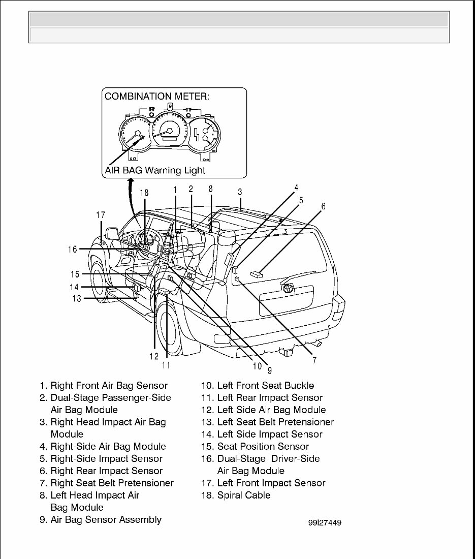
2003 ACCESSORIES/SAFETY EQUIPMENT Toyota - Air Bag Restraint Systems DESCRIPTION & OPERATION Supplemental Restraint System (SRS), also known as air bag system, is designed to provide increased accident protection for driver, front and rear passengers by deploying air bags in a front-end or side collision. The air bag system is designed to be used in conjunction with 3-point seat belts. The air bag system includes the following components: dual-stage driver-side air bag module, dual-stage passenger-side air bag module, spiral cable, right and left side air bag modules, right and left front seat belt pretensioners, AIR BAG warning light, air bag sensor assembly, right and left head impact/side air bag sensors, right and left front impact sensors, right and left rear impact sensors, left front seat position sensor and associated wiring harnesses. See COMPONENT LOCATIONS . COMPONENT LOCATIONS Refer to illustration for component locations. See Fig. 1 . WARNING: Accidental air bag deployment is possible. Personal injury may result. Read and follow all WARNINGS and AIR BAG SAFETY PRECAUTIONS before working on air bag system or related components. 2003 Toyota 4Runner Limited 2003 ACCESSORIES/SAFETY EQUIPMENT Toyota - Air Bag Restraint Systems 2003 Toyota 4Runner Limited 2003 ACCESSORIES/SAFETY EQUIPMENT Toyota - Air Bag Restraint Systems
Fig. 1: Locating Restraint System Components 2003 Toyota 4Runner Limited 2003 ACCESSORIES/SAFETY EQUIPMENT Toyota - Air Bag Restraint Systems
Courtesy of TOYOTA MOTOR SALES, U.S.A., INC. SYSTEM OPERATION CHECK Turn ignition switch to ACC or ON position. AIR BAG warning light should come on for about 6 seconds and then go out. If AIR BAG warning light does not operate as specified, see DIAGNOSTICS . AIR BAG SAFETY PRECAUTIONS Observe the following precautions when servicing air bag system: Disable air bag system before servicing any air bag system or steering column component. Failure to do this could result in accidental air bag deployment and possible personal injury. See DISABLING & ACTIVATING AIR BAG SYSTEM . When diagnosing air bag system, always check for diagnostic codes before disconnecting battery. After turning ignition switch to LOCK position and disconnecting negative battery cable, wait at least 90 seconds before working on air bag system. Air bag system is equipped with a back-up power source that may allow air bag to deploy until 90 seconds after disconnecting negative battery cable. If vehicle was in a minor collision but air bags did not deploy, inspect all system components for any sign of damage, and replace as necessary. Never use air bag system components from another vehicle. Replace air bag system components with NEW parts. Remove air bag sensor assembly, if repairing the vehicle requires impacting (shocking) the vehicle. Air bag sensor assembly contains mercury. After replacement, DO NOT destroy old part. When scrapping vehicle or replacing air bag sensor assembly, remove air bag sensor assembly and dispose of it as toxic waste. Never disassemble and repair air bag sensor assembly or steering wheel pad. Replace dropped, cracked, dented or otherwise damaged components. DO NOT expose air bag sensor assembly, front impact sensors, pretensioners or air bag modules directly to heat or flame. When diagnosing electrical circuits, use a volt/ohm meter with high impedance (10,000 ohms minimum). Information labels are attached to air bag components. Follow all notices on labels. After work on air bag system is complete, check AIR BAG warning light to ensure system is functioning properly. See SYSTEM OPERATION CHECK . Always wear safety glasses when servicing or handling an air bag. When placing a live air bag on a bench or other surface, always face air bag and trim cover up and away from surface. This will reduce motion of module if it is accidentally deployed. After deployment, air bag surface may contain deposits of sodium hydroxide, which irritates skin. Always wear safety glasses, rubber gloves, and long-sleeved shirt during clean- up. After clean-up, wash hands using mild soap and water. Carry a live air bag module with trim cover (air bag) pointed away from your body to minimize injury in case accidental deployment. 2003 Toyota 4Runner Limited 2003 ACCESSORIES/SAFETY EQUIPMENT Toyota - Air Bag Restraint Systems
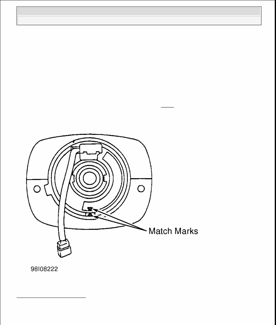
If air bag system is not fully functional for any reason, vehicle should not be driven until system is repaired and again becomes operational. DO NOT remove bulbs, modules, sensors or other components, or in any way disable system from operating normally. If air bag system is not functional, park vehicle until it is repaired and functions properly. ADJUSTMENTS CENTERING SPIRAL CABLE Ensure air bag system is disabled. Turn spiral cable counterclockwise until it becomes difficult to turn. Turn spiral cable clockwise about 2 1/2 turns to align match marks. See Fig. 2 . Install steering wheel. Fig. 2: Adjusting Spiral Cable Courtesy of TOYOTA MOTOR SALES, U.S.A., INC. DISABLING & ACTIVATING AIR BAG SYSTEM 2003 Toyota 4Runner Limited 2003 ACCESSORIES/SAFETY EQUIPMENT Toyota - Air Bag Restraint Systems
DISABLING SYSTEM Turn ignition switch to LOCK position. Disconnect and shield negative battery cable. Wait at least 90 seconds before starting any work on vehicle. ACTIVATING SYSTEM For Component Replacement Ensure ignition switch is in LOCK position. Reconnect negative battery cable. Perform system operation check. See SYSTEM OPERATION CHECK . DISPOSAL PROCEDURES ON-VEHICLE DEPLOYMENT (SCRAPPED VEHICLES ONLY) Dual-stage Driver- & Passenger-side AIR Bag Module 1. Before proceeding, see AIR BAG SAFETY PRECAUTIONS . Ensure steering wheel, driver-side air bag module and passenger-side air bag modules are not loose. If components are loose, deploy air bag(s) using OFF - VEHICLE DEPLOYMENT procedure. Test Deployment Tool (09082-00700). See TESTING DEPLOYMENT TOOL . 2. If deploying driver-side air bag module, access and disconnect spiral cable connector accessible by removing lower steering column cover. If deploying passenger-side air bag module, access and disconnect passenger-side air bag connector by removing glove box. See Fig. 3 . For either air bag, connect Deployment Tools (09082-00700 and 09082-00780) to air bag module connector. Position deployment tool at least 33 feet (10 m) from front of vehicle. 3. Close all doors and windows of vehicle. Connect deployment tool Red clip to positive battery terminal and Black clip to negative battery terminal. Ensure no one is inside or within 33 feet (10 m) of vehicle. WARNING: Unintentional air bag module deployment is possible. Personal injury may result. Never use memory savers when working on air bag system. Unintentional air bag module deployment is possible. Personal injury may result. Back-up power supply maintains air bag system voltage for about 90 seconds after battery is disconnected. After disabling air bag system, wait at least 90 seconds before servicing air bag system. WARNING: Undeployed air bags contain substances that can cause illness or injury if improperly handled. Disposing of an undeployed air bag may violate federal, state and/or local laws. If scrapping vehicle, air bag must be deployed while still mounted in vehicle. Air bags should not be deployed inside vehicle unless vehicle is to be scrapped. If not scrapping vehicle, use off-vehicle deployment procedures. See OFF - VEHICLE DEPLOYMENT . Wear gloves and safety glasses when handling air bag. Wrap deployed air bag in a sturdy plastic bag and dispose of it like any other part. 2003 Toyota 4Runner Limited 2003 ACCESSORIES/SAFETY EQUIPMENT Toyota - Air Bag Restraint Systems
The 2003-2008 Toyota 4Runner Service & Repair Manual offers complete factory-level servicing instructions for both the V6 and V8 versions of the fourth-generation 4Runner. Whether you're maintaining the robust 4.0L 1GR-FE or the powerful 4.7L 2UZ-FE, this manual delivers accurate procedures and diagrams straight from Toyota's service network.
Inside, you'll find detailed coverage across engine, drivetrain, electrical, HVAC, emissions, and chassis systems—including separate procedures for power steering and suspension depending on engine type. From engine overhaul to electrical diagnostics and everything in between, it’s the go-to reference for technicians and skilled DIYers working on this generation of 4Runner.
Content Overview:
Covers detailed maintenance procedures and service intervals
Full engine repair manuals for both 1GR-FE (4.0L V6) and 2UZ-FE (4.7L V8) engines
Includes sections for timing belt, intake, exhaust, and ignition systems
Cooling, lubrication, and charging system diagnostics and specs
Comprehensive transmission and drivetrain repair, including driveshaft and differential servicing
Suspension system coverage, including both standard and rear air suspension
Power steering repair manuals (separate guides for 1GR and 2UZ engines)
Full HVAC and heating system diagnostics (including HVAC wiring and diagnosis)
Electrical troubleshooting including wiring diagrams and fuse box layout
Covers ABS, disc brakes, parking brake systems, and brake control modules
Steering column, steering rack, and related components breakdown
Emissions control system documentation for both engine types
Full body repair sections including doors, mirrors, seats, sunroof, and interior trim
Audio/visual, cruise control, navigation, and instrument panel wiring
Diagnostic procedures for airbags and supplemental restraint systems
Includes component location diagrams for electrical and engine systems
Final section with service specifications and preparation guidelines
Whether you're tackling routine maintenance or a major system overhaul, this manual gives you the OEM-level clarity and accuracy to get it done right.
Printable: Yes Language: English Compatibility: Pretty much any electronic device Requirements: Adobe Reader (free)