
 Service & Repair Manual")
INTRODUCTION HOW TO USE THIS MANUAL −
IN−1
HOW TO USE THIS MANUAL
To assist you in finding your way through the manual, the Section Title and major heading are given
at the top of every page.
PREPARATION
Preparation lists the SST (Special Service Tools), recommended tools, equipment, lubricant and SSM
(Special Service Materials) which should be prepared before beginning the operation and explains the
purpose of each one.
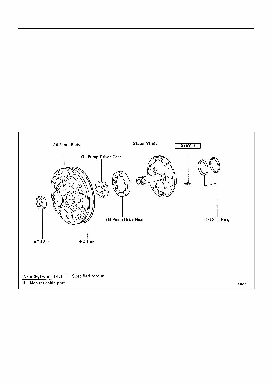
REPAIR PROCEDURES
Most repair operations begin with an overview illustration. It identifies the components and shows how
the parts fit together.
Example:
IN002−0T
INTRODUCTION HOW TO USE THIS MANUAL −
IN−2
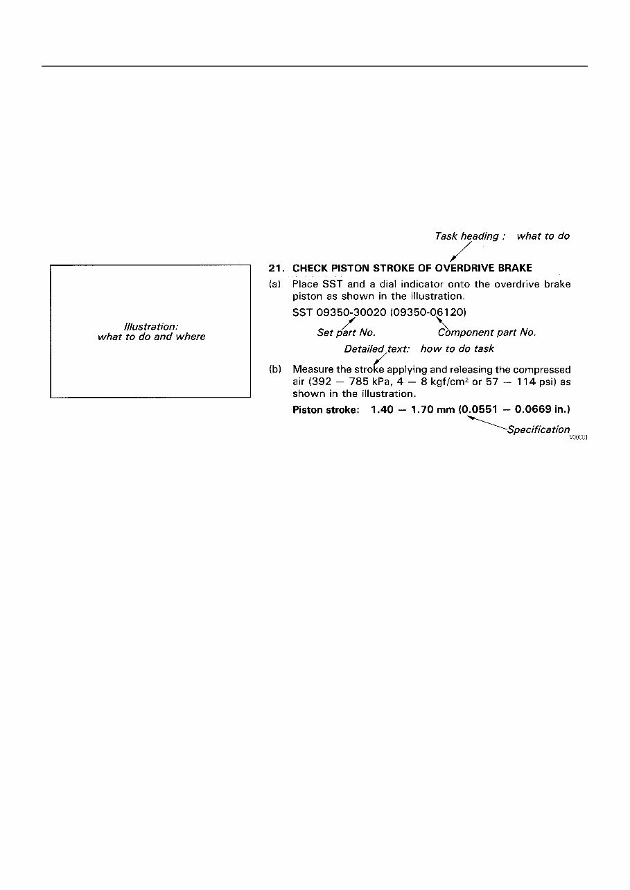
The procedures are presented in a step−by−step format:
D The illustration shows what to do and where to do it.
D The task heading tells what to do.
D The detailed text tells how to perform the task and gives other information such as specifications
and warnings.
Example:
This format provides the experienced technician with a FAST TRACK to the information needed. The
upper case task heading can be read at a glance when necessary, and the text below it provides de-
tailed information. Important specifications and warnings always stand out in bold type.
REFERENCES
References have been kept to a minimum. However, when they are required you are given the page
to refer to.
SPECIFICATIONS
Specifications are presented in bold type throughout the text where needed.You never have to leave
the procedure to look up your specifications. They are also found at the back of AT section, for quick
reference.

INTRODUCTION HOW TO USE THIS MANUAL −
IN−3
CAUTIONS, NOTICES, HINTS:
D CAUTIONS are presented in bold type, and indicate there is a possibility of injury to you or other
people.
D NOTICES are also presented in bold type, and indicate the possibility of damage to the compo-
nents being repaired.
D HINTS are separated from the text but do not appear in bold. They provide additional information
to help you perform the repair efficiently.
SI UNIT
The UNITS given in this manual are primarily expressed according to the SI UNIT (International System
of Unit), and alternately expressed in the metric system and in the English system.
Example:
Torque: 30 N·m (310 kgf·cm, 22 ft·lbf)

INTRODUCTION GLOSSARY OF SAE AND TOYOTA TERMS −
IN−7
GLOSSARY OF SAE AND TOYOTA TERMS
This glossary lists all SAE−J1930 terms and abbreviations used in this manual in compliance with SAE
recommendations, as well as their Toyota equivalents.
SAE
ABBREVIATIONS
SAE TERMS
TOYOTA TERMS
( )−−ABBREVIATIONS
A/C Air Conditioning Air Conditioner
ACL Air Cleaner Air Cleaner
AIR Secondary Air Injection Air Injection (AI)
AP Accelerator Pedal −
B+ Battery Positive Voltage +B, Battery Voltage
BARO Barometric Pressure −
CAC Charge Air Cooler Intercooler
CARB Carburetor Carburetor
CFI Continuous Fuel Injection −
CKP Crankshaft Position Crank Angle
CL Closed Loop Closed Loop
CMP Camshaft Position Cam Angle
CPP Clutch Pedal Position −
CTOX Continuous Trap Oxidizer −
CTP Closed Throttle Position −
DFI Direct Fuel Injection (Diesel) Direct Injection (DI)
DI Distributor Ignition −
DLC1
DLC2
DLC3
Data Link Connector 1
Data Link Connector 2
Data Link Connector 3
1: Check Connector
2: Toyota Diagnosis Communication Link (TDCL)
3: OBD II Diagnostic Connector
DTC Diagnostic Trouble Code Diagnostic Code
DTM Diagnostic Test Mode −
ECL Engine Control Level −
ECM Engine Control Module Engine ECU (Electronic Control Unit)
ECT Engine Coolant Temperature Coolant Temperature, Water Temperature (THW)
EEPROM
Electrically Erasable Programmable Read Only
Memory
Electrically Erasable Programmable Read Only Memory
(EEPROM),
Erasable Programmable Read Only Memory (EPROM)
EFE Early Fuel Evaporation Cold Mixture Heater (CMH), Heat Control Valve (HCV)
EGR Exhaust Gas Recirculation Exhaust Gas Recirculation (EGR)
EI Electronic Ignition Toyota Distributorless Ignition (TDI)
EM Engine Modification Engine Modification (EM)
EPROM Erasable Programmable Read Only Memory Programmable Read Only Memory (PROM)
EVAP Evaporative Emission Evaporative Emission Control (EVAP)
FC Fan Control −
FEEPROM
Flash Electrically Erasable Programmable
Read Only Memory
−
FEPROM Flash Erasable Programmable Read Only Memory −
FF Flexible Fuel −
FP Fuel Pump Fuel Pump
GEN Generator Alternator
GND Ground Ground (GND)
HO2S Heated Oxygen Sensor Heated Oxygen Sensor (HO2S)
IN016−02

INTRODUCTION GLOSSARY OF SAE AND TOYOTA TERMS −
IN−8
IAC Idle Air Control Idle Speed Control (ISC)
IAT Intake Air Temperature Intake or Inlet Air Temperature
ICM Ignition Control Module −
IFI Indirect Fuel Injection Indirect Injection
IFS Inertia Fuel−Shutoff −
ISC Idle Speed Control −
KS Knock Sensor Knock Sensor
MAF Mass Air Flow Air Flow Meter
MAP Manifold Absolute Pressure
Manifold Pressure
Intake Vacuum
MC Mixture Control
Electric Bleed Air Control Valve (EBCV)
Mixture Control Valve (MCV)
Electric Air Control Valve (EACV)
MDP Manifold Differential Pressure −
MFI Multiport Fuel Injection Electronic Fuel Injection (EFI)
MIL Malfunction Indicator Lamp Check Engine Light
MST Manifold Surface Temperature −
MVZ Manifold Vacuum Zone −
NVRAM Non−Volatile Random Access Memory −
O2S Oxygen Sensor Oxygen Sensor, O
2
Sensor (O
2
S)
OBD On−Board Diagnostic On−Board Diagnostic (OBD)
OC Oxidation Catalytic Converter Oxidation Catalyst Converter (OC), CCo
OP Open Loop Open Loop
PAIR Pulsed Secondary Air Injection Air Suction (AS)
PCM Powertrain Control Module −
PNP Park/Neutral Position −
PROM Programmable Read Only Memory −
PSP Power Steering Pressure −
PTOX Periodic Trap Oxidizer
Diesel Particulate Filter (DPF)
Diesel Particulate Trap (DPT)
RAM Random Access Memory Random Access Memory (RAM)
RM Relay Module −
ROM Read Only Memory Read Only Memory (ROM)
RPM Engine Speed Engine Speed
SC Supercharger Supercharger
SCB Supercharger Bypass −
SFI Sequential Multiport Fuel Injection Electronic Fuel Injection (EFI), Sequential Injection
SPL Smoke Puff Limiter −
SRI Service Reminder Indicator −
SRT System Readiness Test −
ST Scan Tool −
TB Throttle Body Throttle Body
TBI Throttle Body Fuel Injection
Single Point Injection
Central Fuel Injection (Ci)
TC Turbocharger Turbocharger
TCC Torque Converter Clutch Torque Converter
TCM Transmission Control Module Transmission ECU (Electronic Control Unit)
TP Throttle Position Throttle Position
TR Transmission Range −

INTRODUCTION GLOSSARY OF SAE AND TOYOTA TERMS −
IN−9
TVV Thermal Vacuum Valve
Bimetallic Vacuum Switching Valve (BVSV)
Thermostatic Vacuum Switching Valve (TVSV)
TWC Three−Way Catalytic Converter
Three−Way Catalyst (TWC)
CC
RO
TWC+OC Three−Way + Oxidation Catalytic Converter CC
R
+ CCo
VAF Volume Air Flow Air Flow Meter
VR Voltage Regulator Voltage Regulator
VSS Vehicle Speed Sensor Vehicle Speed Sensor (Read Switch Type)
WOT Wide Open Throttle Full Throttle
WU−OC Warm Up Oxidation Catalytic Converter −
WU−TWC Warm Up Three−Way Catalytic Converter Manifold Converter
3GR Third Gear −
4GR Fourth Gear −
A340E (2JZ−GTE) AUTOMATIC TRANSMISSION PREPARATION −
AT−10
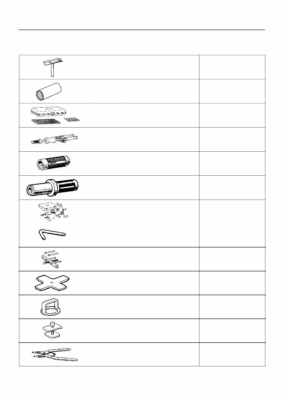
PREPARATION
SST (SPECIAL SERVICE TOOLS)
09032−00100 Oil Pan Seal Cutter
09060−20100 Deeper Socket Wrench 30 mm L
09240−00020 Wire Gauge Set
09308−00010 Oil Seal Puller
09309−37010 Transmission Bearing Replacer
09325−40010 Transmission Oil Plug
09350−30020 TOYOTA Automatic Transmission
Tool Set
(09350−06120) No.2 Measure Terminal
(09350−07020) Oil Pump Puller
(09350−07030) No.1 Piston Spring Compressor
(09350−07040) No.2 Piston Spring Compressor
(09350−07050) No.3 Piston Spring Compressor
(09350−07060) No.1 Snap Ring Expander
AT0D6−04
A340E (2JZ−GTE) AUTOMATIC TRANSMISSION PREPARATION −
AT−11
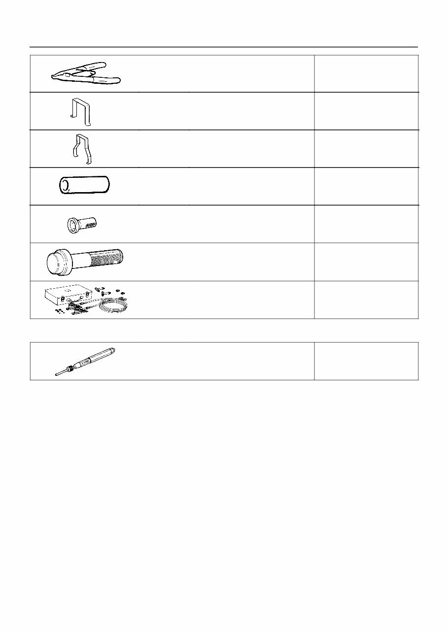
(09350−07070) No.2 Snap Ring Expander
(09350−07080) Brake Reaction Sleeve Puller
(09350−07090) Brake No.1 Piston Puller
(09350−07110) Oil Seal Replacer
(09351−32140) Oil Seal Replacer
09517−36010 Rear Axle Shaft Oil Seal
Replacer−
09992−00094 Automatic Transmission Oil
Pressure Gauge Set
RECOMMENDED TOOLS
09031−00030 Pin Punch .
AT0D7−03

A340E (2JZ−GTE) AUTOMATIC TRANSMISSION PREPARATION −
AT−12
EQUIPMENT
Feeler gauge Check major clearance.
Vernier calipers Check length of second coast
brake piston rod.
Dial indicator or dial indicator with magnetic base Check piston stroke and play of
the output shaft.
Dial indicator Check inside diameter of major
bushing.
Straight edge Check side clearance of oil pump.
Torque wrench
Cylinder gauge Check inside diameter of the
transmission case rear bushing.
Ohmmeter
Voltmeter
Ammeter(A)
LUBRICANT
Item Capacity Classification
Dry fill
Drain and refill
8.2 liters (8.7 US qts, 7.2 Imp. qts)
1.9 liters (2.0 US qts, 1.7 Imp. qts)
ATF Type T−II or equivalent
SSM (SPECIAL SERVICE MATERIALS)
08826−00090 Seal Packing 1281,
THREE BOND 1281 or equivalent
(FIPG)
Oil pan
08833−00070 Adhesive 1324,
THREE BOND 1324 or equivalent
Torque converter clutch housing
Extension housing
PNP switch
AT0D8−03
AT0D9−02
AT0DA−05
INTRODUCTION STANDARD BOLT TORQUE SPECIFICATIONS −
IN−20
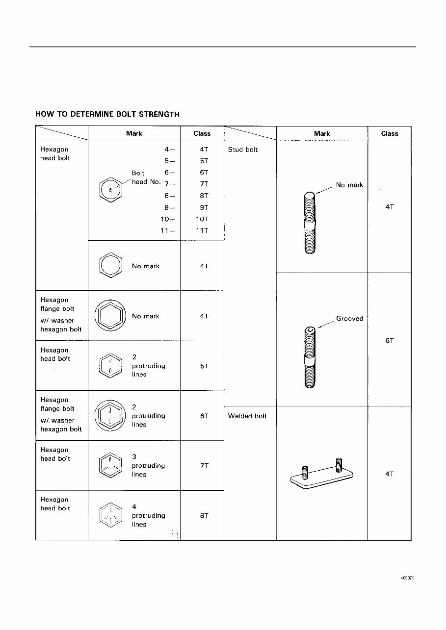
STANDARD BOLT TORQUE SPECIFICATIONS
IN008−02
You're Reading a Preview
What's Included?
Fast Download Speeds
Online & Offline Access
Access PDF Contents & Bookmarks
Full Search Facility
Print one or all pages of your manual
$31.99
1994 Toyota 4Runner Previa Supra T100 Tacoma Truck A340 Automatic Transmission Manual (RM391U) Service & Repair Manual
Viewed 18 Times Today

What's Included?
Fast Download Speeds
Online & Offline Access
Access PDF Contents & Bookmarks
Full Search Facility
Print one or all pages of your manual
$31.99

Secure transaction
What's Included?
Fast Download Speeds
Online & Offline Access
Access PDF Contents & Bookmarks
Full Search Facility
Print one or all pages of your manual
Description
The 1994 Toyota 4Runner Previa Supra T100 Tacoma Truck A340 Automatic Transmission manual is a comprehensive technical guide designed for both professional mechanics and DIY enthusiasts. This resource provides detailed information and instructions for troubleshooting, repairing, and maintaining the vehicle's transmission system.
- It covers essential topics such as component identification, troubleshooting procedures, and maintenance schedules.
- The manual is an invaluable tool for anyone who needs to perform repairs, maintenance, or upgrades on their vehicle.
- With its technical language and detailed diagrams, it is suitable for both professionals and DIYers who want to gain a deeper understanding of their vehicle's inner workings.
- This manual is an ideal resource for anyone looking to troubleshoot and fix issues, as well as for those who want to gain a deeper understanding of their vehicle's transmission system.


