1 1 2 2 3 3 4 4 5 5 6 6 D D C C B B A A 1004573-00-D 09 (final) 5/13/2014 1.1 Table of Contents ITEM NO. PROJECT NAME: DO NOT SCALE REVISION: DATE: SHEET Model S Wiring Diagram: LHD PHASE: SHEET NAME: SOP(2012) THE INFORMATION CONTAINED HEREIN IS DEEMED TO BE CONFIDENTIAL, PROPRIETARY, AND A TRADE SECRET OF TESLA MOTORS. THIS INFORMATION MAY NOT BE USED, REPRODUCED, OR DISCLOSED AS THE DIRECT OR INDIRECT BASIS FOR THE DEVELOPMENT, MANUFACTURE, OR SALE OF PROCESSES OR PRODUCTS WITHOUT THE EXPRESSED WRITTEN CONSENT OF TESLA MOTORS. 1 2 3 4 Table of Contents and Legend Change History Base Audio wiring Premium Audio wiring (in addition to base wiring) 5 Antenna connections 6 7 8 Infotainment non-Antenna connections MCU/Infotainment vehicle interfaces Security, Passive Entry, Horns 9 Chassis - Stability and ABS, park brake 10 11 Chassis - Power Steering and Steering wheel controls Chassis - Air suspension system 12 Body - LF Door (see section 31 for side mirror) 13 14 15 Body - LR Door Body - RF Door (see section 31 for side mirror) Body - RR Door 16 Powertrain - HV Battery and Chargers 17 18 19 Body - Exterior Lights, Front Body - Exterior Lights, Rear, inlcuding Tailgate Body - Front Cargo Hatch 20 Body - Rear Cargo Hatch / Power Liftgate 21 22 HVAC - Thermal Controller Sensors, Valves and Inlet Louvers HVAC - Coolant Pumps / Condenser Fans / Cabin Function 23 24 HVAC - Thermal Controller, Solenoids, Relay Drive, Rear Defrost, Air PTC, Compressor Powertrain - HVIL and High Voltage architecture 25 Body - Wiper/Washer System 26 27 Passive Safety Restraints System Body - Overhead controle module, Intrusion/Tow detection, Powered Sunroof 28 Powertrain - Drive Inverter, Accelerator Pedal 29 30 31 Body - LF Seat Body - RF Seat Body - Side Mirrors 32 Body - Interior Lighting Section DESCRIPTION 33 Parking Aids, Rear View Camera 34 Advanced Safety - Blind Zone and Forward Camera 35 Chassis CAN Network 36 Body CAN Network 37 Body Fault-Tolerant CAN Network 38 PowerTrain CAN Network 39 Diagnostic Connections 40 Battery and Permanent Power Distribution 41 Siwtched 12V Power Distribution 42 Ground Distribution 43 Layout and Function of Fuse/Relay Boxes
1 1 2 2 3 3 4 4 5 5 6 6 D D C C B B A A 1004573-00-D 09 (final) 5/13/2014 1.2 Legend ITEM NO. PROJECT NAME: DO NOT SCALE REVISION: DATE: SHEET Model S Wiring Diagram: LHD PHASE: SHEET NAME: SOP(2012) THE INFORMATION CONTAINED HEREIN IS DEEMED TO BE CONFIDENTIAL, PROPRIETARY, AND A TRADE SECRET OF TESLA MOTORS. THIS INFORMATION MAY NOT BE USED, REPRODUCED, OR DISCLOSED AS THE DIRECT OR INDIRECT BASIS FOR THE DEVELOPMENT, MANUFACTURE, OR SALE OF PROCESSES OR PRODUCTS WITHOUT THE EXPRESSED WRITTEN CONSENT OF TESLA MOTORS. pin # male female AAA##-H# C Z_W S##T## H# = [H]arness (table 3) and Branch (#) AAA## combination is same across all sheets/harnesses for the same circuit C = wire color (table 4) Z = wire size in mm^2 (see note 4). A trailing 'f' indicates flexible type (smaller stranding) wire splice Z# = splice designator DES designator multi-way connector/ twisted # module (partial) pin number pair shield (table 2) contact contact module (complete) optional content Optional Content Note inside dotted box dashed lines indicate contacts are in same connector MODULE1 NET1 1.2[4B] NET1 1.2[2B] arrow away from module or connector indicates a signal driven to another sheet in wiring diagram sheet number [zone] for source connection sheet number [zone] for destination connection X### MODULE2 pin name arrow toward module or connector indicates a signal driven from another sheet in wiring diagram pin name pin name # X### Global connector number. Dotted line used between pins on same connector pin number # Global connector number. (may appear at top when only one connector on module) module descriptive name Two wires crimped into one pin AAA = subsystem group ID. ## = circuit number T## = twist group ## (if any) new numbering sequence per harness S## = shield group (if any) new numbering sequence per harness W = wire type designation, if not default (see sheet 1.3 for wire type codes) 1 2 3 1 2 3 Z# PONET1
1 1 2 2 3 3 4 4 5 5 6 6 D D C C B B A A 1004573-00-D 09 (final) 5/13/2014 1.3 Notes, Abbreviations, etc. ITEM NO. PROJECT NAME: DO NOT SCALE REVISION: DATE: SHEET Model S Wiring Diagram: LHD PHASE: SHEET NAME: SOP(2012) THE INFORMATION CONTAINED HEREIN IS DEEMED TO BE CONFIDENTIAL, PROPRIETARY, AND A TRADE SECRET OF TESLA MOTORS. THIS INFORMATION MAY NOT BE USED, REPRODUCED, OR DISCLOSED AS THE DIRECT OR INDIRECT BASIS FOR THE DEVELOPMENT, MANUFACTURE, OR SALE OF PROCESSES OR PRODUCTS WITHOUT THE EXPRESSED WRITTEN CONSENT OF TESLA MOTORS. Table 2: Multi-way Connector Designators Striped wires are indicated by base-color code "-" then stripe color code. "BR-BK" indicates a brown wire with a black stripe. LFDHC LRDHC RFDHC RRDHC TGHC LF Door Harness Connector LR Door Harness Connector RF Door Harness Connector RR Door Harness Connector TailGate Harness Connector Table 1: Abbreviations LF RF LR RR Left Front Right Front Left Rear Right Rear LC Left Child (rear-facing) RC Right Child (rear-facing) MF Middle Front - - - - - - CCHC Center Console Harness Connector IPHC(L/R) Instrument Panel Harness Conenctor (Left/Right) RSFHC Rear Subframe harness connector - - - - Table 3: Harness Designators D F P Driver (LF) Door Harness Front Bumper Harness Front Passenger (RF) Door Harness R LR Door Harness S RR Door Harness T Tailgate Harness - Right J Instrument Panel (Dashpad) Harness Table 4: Wire Color Designators BK BR DB Black Brown Dark Blue OR Orange PK Pink GY Gray LB Light Blue LG Light Green PU Purple RD Red NA coax-center SH coax-shield - - - - TN Tan WH White YL Yellow - - E Sunroof Subsystem Harness Q Front Harness, Left side K Headliner G Rear Bumper Harness H High Voltage Wiring (for reference only) V HVAC Unit Subharness (part of assembly) W Steering Wheel Harness (from Clockspring out) C Center Console X Rear subframe subharness Y tbd A Body Harness, Left Floor B Body Harness, Right Floor U Tailgate Harness - Left DG Dark Green L Front End Module Z Single Cables - Each circuit is a separate assembly M Main Harness, Lower IP and Front Trunk area N Front Harness, Right Side Table 5: Wire Type Designators TWP SAE J1128 TWP : thin-wall 105C rated TXL SAE J1128 TXL : thin-wall 125C rated STX SAE J1127 STX : thin-wall 125C rated SGX SAE J1127 SGX : general purpose 125C rated -f flexible type (add to any type) = small strand RFXFA SAE J1128 TXL-f: thin-wall high-flex 125C rated General Notes: 1) Switches [Relays] are shown in their inactive [de-energized] state. 2) Splices may be split across pages for visual clarity with respect to the function 3) Some connectors are split across multiple pages for clarity. There is no overall reference in this document for the signals routed to a specific connector. 0) Document is formatted to print on 8.5" x 11" paper. (similar to A4) displayed on the particular page. 4) Wire sizes are specified in mm^2 cross-sectional area (CSA) per SAE 1127/8 Size Shown Wire Specification Usage 0.22 SAE 0.22 / 24AWG 0.35 SAE 0.35 / 22AWG 0.5 SAE 0.5 / 20 AWG 0.75 SAE 0.8 / 18AWG 1.0 SAE 1.0 / 16AWG 2.0 SAE 2.0 / 14AWG 3.0 SAE 3.0 / 12AWG 5.0 SAE 5.0 / 10AWG 5) Wire specification: 60V, thin-wall PVC (SAE TWP type or equivalent), unless otherwise specified in wire label. 6) Unless otherwise specified, terminal plating is to be Tin or Pre-Tin Twisted pairs may be manufactured of above wire by harness manufacturer. See sheet 43 for further details and to correlate specific cabling types to harness application P=30mm +/-5mm for CSA<=1.0 8.0 SAE 8.0 / 8AWG 13.0 SAE 13.0 / 6AWG 20.0 SAE 19.0 / 4AWG 32.0 SAE 32.0 / 2AWG See sheet 1.2 for a description of how the wire types are shown in the wire label. P=60mm +/-5mm for CSA>1.0 7) For connectors with multiple instances of the same wire color in a similar or the same size, the terminal may not be inserted into the exact cavity specified. This applies only to joint connectors in the G### range or X700-X799 range, where the wires are connected together internally by the joint connector. 8) Inline conenctor gender specification is based on the terminal type. Inline connectors with "M" suffix have male, tab or pin terminals Inline connectors with "F" suffix have female, receptacle or socket terminals WireType Default TWP PARAM PRM1 COPRM1
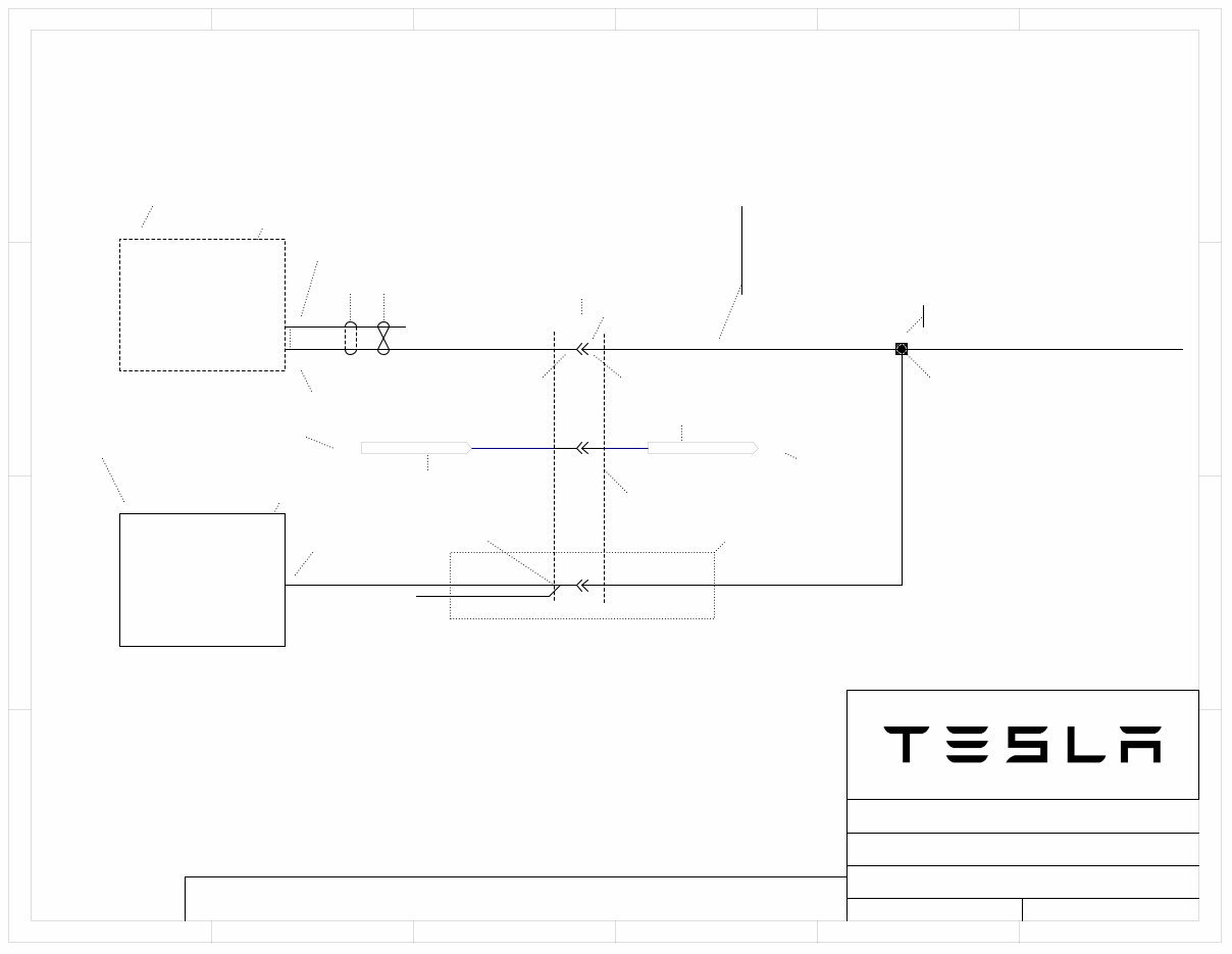
1 1 2 2 3 3 4 4 5 5 6 6 D D C C B B A A 1004573-00-D 09 (final) 5/13/2014 3.1 Audio Wiring - Base - Power / Line-In ITEM NO. PROJECT NAME: DO NOT SCALE REVISION: DATE: SHEET Model S Wiring Diagram: LHD PHASE: SHEET NAME: SOP(2012) THE INFORMATION CONTAINED HEREIN IS DEEMED TO BE CONFIDENTIAL, PROPRIETARY, AND A TRADE SECRET OF TESLA MOTORS. THIS INFORMATION MAY NOT BE USED, REPRODUCED, OR DISCLOSED AS THE DIRECT OR INDIRECT BASIS FOR THE DEVELOPMENT, MANUFACTURE, OR SALE OF PROCESSES OR PRODUCTS WITHOUT THE EXPRESSED WRITTEN CONSENT OF TESLA MOTORS. Center Display GND_MCU_AUD 42.3[4A] F6_20A_BASE_AUDIO 41.3[4B] X900:IPHCR1 PAC03-J YL-BR 3.0 PAC03-M YL-BR 3.0 GDC04-M BK 3.0 X425 ACC 7 ACC 8 KL31 9 KL31 10 Z1 Z2 PAC03-J1 YL-BR 2.0 PAC03-J2 YL-BR 2.0 3 4 3 4 PRM10-M RD-YL 2.0 F51_20A_MCU_PERM 40.5[5B] X900:IPHCR1 X426 KL30 7 KL30 8 Z3 5 5 X440 Aux_L+ 7 Aux_L- 6 Aux_R+ 15 Aux_R- 14 Aux_SHLD 5 Aux_SHLD 13 Radio Head Unit PRM10-J RD-YL 2.0 PRM10-J1 RD-YL 2.0 PRM10-J2 RD-YL 2.0 GDC04-J BK 3.0 GDC04-J1 BK 3.0 GDC04-J2 BK 3.0 RadioL- 20 SHLD 19 RadioR- 18 RadioL+ 10 SHLD 9 RadioR+ 8 X430 AUD01-J GY 0.35 S1T1 AUD02-J BR 0.35 S1T1 AUD04-J LB-BK 0.35 S2T2 AUD05-J DB 0.35 S2T2 AUD06-J SH 5.01 S2 AUD03-J SH 5.01 S1 X430, X440 UNSEALED shield terminations GND_MEDIA_IO 6.1[3C] GDC04-J3 BK 1.0 1 J F82 SHIELD REQ48 REQ# Harn Num Spec 2 J F82 SHIELD REQ50 Type COREQ48 COREQ50 PIX42507 PIX42508 PIX42509 PIX425010 COX425B PIX42607 PIX42608 COX426B PIX43008 PIX43009 PIX430010 PIX430018 PIX430019 PIX430020 COX430D PIX44005 PIX44006 PIX44007 PIX440013 PIX440014 PIX440015 COX440B PIX900F03 COX900FC PIX900F04 COX900FD PIX900F05 COX900FE PIX900M03 COX900MC PIX900M04 COX900MD PIX900M05 COX900ME PIZ101 PIZ102 PIZ103 PIZ104 PIZ105 PIZ106 PIZ107 PIZ108 COZ1 PIZ201 PIZ202 PIZ203 PIZ204 PIZ205 PIZ206 PIZ207 PIZ208 COZ2 PIZ301 PIZ302 PIZ303 PIZ304 PIZ305 PIZ306 PIZ307 PIZ308 COZ3 POF6020A0BASE0AUDIO POF51020A0MCU0PERM POGND0MCU0AUD POGND0MEDIA0IO
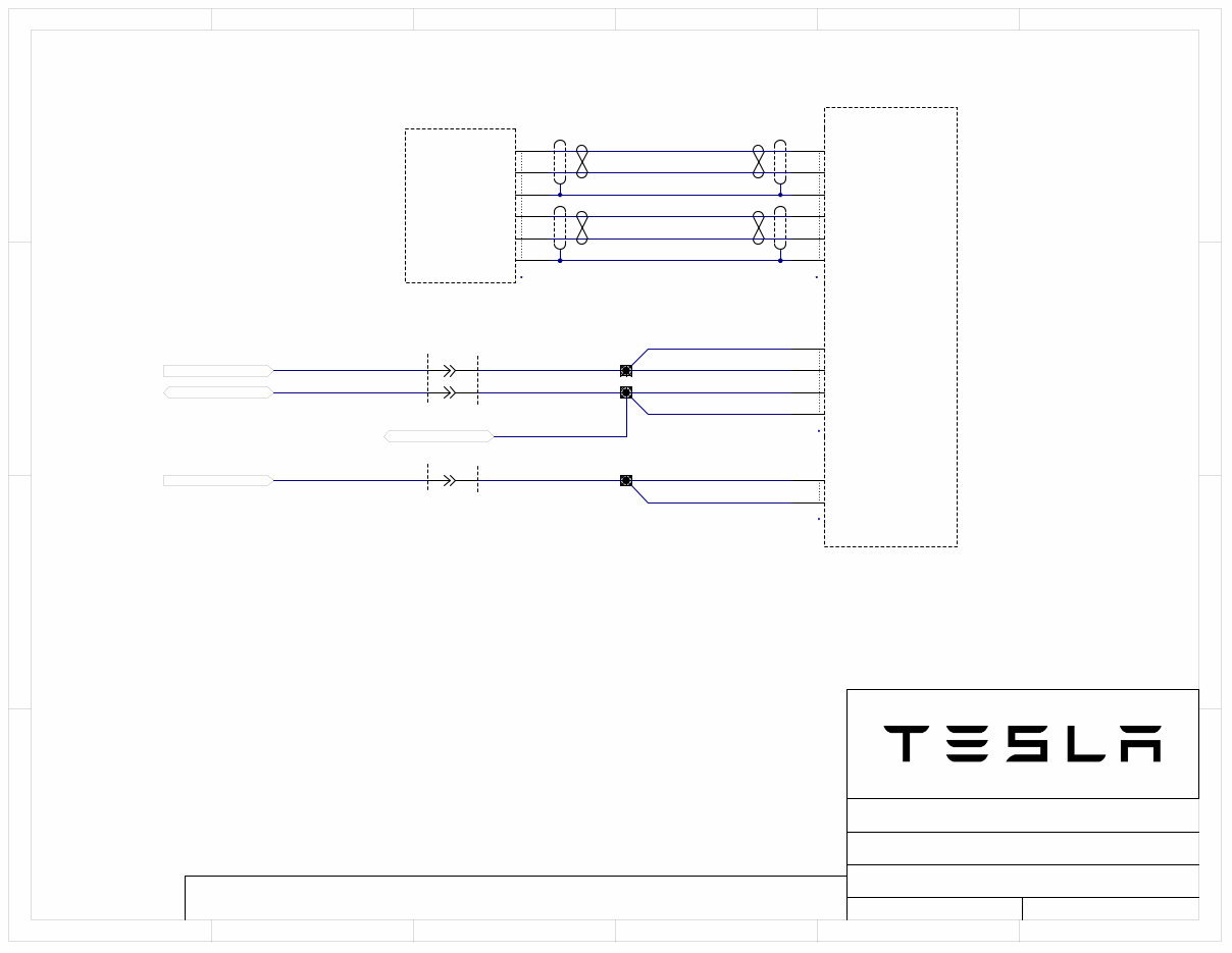
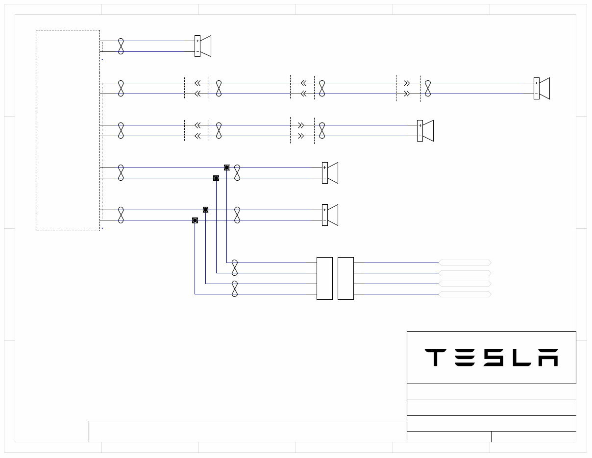
1 1 2 2 3 3 4 4 5 5 6 6 D D C C B B A A 1004573-00-D 09 (final) 5/13/2014 3.2 Audio Wiring - Base - Speakers ITEM NO. PROJECT NAME: DO NOT SCALE REVISION: DATE: SHEET Model S Wiring Diagram: LHD PHASE: SHEET NAME: SOP(2012) THE INFORMATION CONTAINED HEREIN IS DEEMED TO BE CONFIDENTIAL, PROPRIETARY, AND A TRADE SECRET OF TESLA MOTORS. THIS INFORMATION MAY NOT BE USED, REPRODUCED, OR DISCLOSED AS THE DIRECT OR INDIRECT BASIS FOR THE DEVELOPMENT, MANUFACTURE, OR SALE OF PROCESSES OR PRODUCTS WITHOUT THE EXPRESSED WRITTEN CONSENT OF TESLA MOTORS. 1 2 X410 Spkr-CEN 1 2 X413 Spkr-LFT 1 2 X414 Spkr-RFT 1 2 X412 Spkr-RRDoor 1 2 X411 Spkr-LRDoor X938:RRDHC2 X937:LRDHC2 AUD07-J PK 0.75 T3 AUD08-J PK-BK 0.75 T3 Near X423 Z64 Near X423 Z65 Near X423 Z66 Near X423 Z67 AUD09-J PU 2.0 T4 AUD10-J PU-BK 2.0 T4 AUD11-J DG 2.0 T5 AUD12-J DG-BK 2.0 T5 AUD13-J TN 2.0 T6 AUD14-J TN-BK 2.0 T6 AUD15-J BR 2.0 T9 AUD16-J BR-BK 2.0 T9 Media Control Unit - Audio SPK_LF+ 4.2[4A] SPK_LF- 4.2[4A] SPK_RF+ 4.2[4A] SPK_RF- 4.2[4A] 1 2 3 4 X415 1 2 3 4 X409 X425 Center+ 5 Center- 6 X426 Speaker-level Audio Outputs LRDoor+ 9 RRDoor+ 5 LFTwtr+ 3 RFTwtr+ 1 LRDoor- 10 RRDoor- 6 LFTwtr- 4 RFTwtr 2 1 2 1 2 1 2 1 2 AUD13-J1 TN 0.75 T7 AUD14-J1 TN-BK 0.75 T7 AUD15-J1 BR 0.75 T10 AUD16-J1 BR-BK 0.75 T10 AUD13-J2 TN 2.0 T8 AUD14-J2 TN-BK 2.0 T8 AUD15-J2 BR 2.0 T11 AUD16-J2 BR-BK 2.0 T11 AMP21-J2 WH 2.0 T12 AMP22-J2 WH-BK 2.0 T12 AMP23-J2 GY 2.0 T13 AMP24-J2 GY-BK 2.0 T13 1 2 1 2 X970:WWJB 1 2 1 2 X971:WWJM-L AUD09-A PU 2.0 T1 AUD10-A PU-BK 2.0 T1 AUD11-B DG 2.0 T1 AUD12-B DG-BK 2.0 T1 AUD09-R PU 2.0 T1 AUD10-R PU-BK 2.0 T1 AUD11-S DG 2.0 T1 AUD12-S DG-BK 2.0 T1 AUD09-M PU 2.0 T1 AUD10-M PU-BK 2.0 T1 X950:WWMA1 1 2 1 2 X409 connected to X415 for base audio ONLY. PIX40901 PIX40902 PIX40903 PIX40904 COX409 PIX41001 PIX41002 COX410 PIX41101 PIX41102 COX411 PIX41201 PIX41202 COX412 PIX41301 PIX41302 COX413 PIX41401 PIX41402 COX414 PIX41501 PIX41502 PIX41503 PIX41504 COX415 PIX42505 PIX42506 COX425C PIX42601 PIX42602 PIX42603 PIX42604 PIX42605 PIX42606 PIX42609 PIX426010 COX426A PIX937F01 COX937FA PIX937F02 COX937FB PIX937M01 COX937MA PIX937M02 COX937MB PIX938F01 COX938FA PIX938F02 COX938FB PIX938M01 COX938MA PIX938M02 COX938MB PIX950F01 COX950FA PIX950F02 COX950FB PIX950M01 COX950MA PIX950M02 COX950MB PIX970F01 COX970FA PIX970F02 COX970FB PIX970M01 COX970MA PIX970M02 COX970MB PIX971F01 COX971FA PIX971F02 COX971FB PIX971M01 COX971MA PIX971M02 COX971MB PIZ6401 PIZ6402PIZ6403 PIZ6404 PIZ6405 PIZ6406 PIZ6407 PIZ6408 COZ64 PIZ6501 PIZ6502PIZ6503 PIZ6504 PIZ6505 PIZ6506 PIZ6507 PIZ6508 COZ65 PIZ6601 PIZ6602 PIZ6603 PIZ6604 PIZ6605 PIZ6606 PIZ6607 PIZ6608 COZ66 PIZ6701 PIZ6702 PIZ6703PIZ6704 PIZ6705 PIZ6706 PIZ6707 PIZ6708 COZ67 POSPK0LF0 POSPK0RF0
You're Reading a Preview
What's Included?
Lifetime Access
Fast Download Speeds
Offline Viewing
Access Contents & Bookmarks
Full Search Facility
Print one or all pages of your manual
$48.99
2012 Tesla Model S OEM Download Service & Repair Manual Software
This manual is a comprehensive 2012 Tesla Model S service and repair guide, available in .PDF format. It is an invaluable resource for both professional mechanics and DIY enthusiasts, providing detailed troubleshooting and replacement procedures, step-by-step instructions, clear images, and exploded-view illustrations specific to your model and its variants.
Regular maintenance is essential for the durability of your vehicle. This manual equips you with the manufacturer's recommended maintenance procedures, ensuring the longevity and reliability of your Tesla. It also includes troubleshooting charts to swiftly identify and address any issues based on specific symptoms.
Whether you are a seasoned mechanic or a weekend DIY’er, this manual streamlines the repair process, saving you time and money on repairs and maintenance. It is a one-stop solution for rebuilding the engine, replacing components, and adhering to the manufacturer's specifications, including wiring diagrams and torque specs.
Please note that this manual is not a generic repair guide. It is the same comprehensive software used by professional automotive technicians to service and maintain Tesla vehicles. The digital format allows for easy accessibility, searchability, and compatibility with Windows and Mac systems. Additionally, it is printable for your convenience.
Reviews
Q&A
Recently Viewed
5,521,897Happy Clients
2,594,462eManuals
1,120,453Trusted Sellers
15Years in Business
Price:
Actual Price:
2012 Tesla Model S OEM Download Service & Repair Manual Software