

SUZUKI MARUTI 800 ALTO MB308 Workshop Service Manual
What's Included?
Fast Download Speeds
Online & Offline Access
Access PDF Contents & Bookmarks
Full Search Facility
Print one or all pages of your manual

IMPORTANT
WARNING/CAUTION/NOTE
Please read this manual and follow its instructions
carefully. To emphasize special information, the words
WARNING, CAUTION and NOTE have special mean-
ings. Pay special attention to the messages high-
lighted by these signal words.
WARNING:
Indicates a potential hazard that could result
in death or injury.
CAUTION:
Indicates a potential hazard that could result
in vehicle damage.
NOTE:
Indicates special information to make mainte-
nance easier or instructions clearer.
WARNING:
This service manual is intended for autho-
rized Maruti dealers and qualified service
mechanics only. Inexperienced mechanics
or mechanics without the proper tools and
equipment may not be able to properly per-
form the services described in this manual.
Improper repair may result in injury to the
mechanic and may render the vehicle un-
safe for the driver and passengers.

FOREWORD
This manual contains procedures for diagnosis, maintenance, adjustments, minor service operations,
replacement of components (Service) and for disassembly and assembly of major components (Unit
Repair-Overhaul).
Applicable model: MB308
The contents are classified into sections each of which is given a section number as indicated in the
Table of Contents on next page. And on the first page of each individual section is an index of that
section.
This manual should be kept in a handy place for ready reference of the service work.
Strict observance of the so specified items will enable one to obtain the full performance of the
vehicle.
When replacing parts or servicing by disassembling, it is recommended to use MARUTI genuine
parts, tools and service materials (lubricant, sealants, etc.) as specified in each description.
All information, illustrations and specifications contained in this literature are based on the latest
product information available at the time of publication approval. And used as the main subject of
description is the vehicle of standard specifications among others. Therefore, note that illustrations
may differ from the vehicle being actually serviced.
The right is reserved to make changes at any time without notice.
Related Manual
Manual Name Manual No.
MB308 WIRING DIAGRAM MANUAL 99512M84400-74E
SERVICE DEPARTMENT

6
6A
6B
6C
6E1
6F
6G
6H
6K
7A
7A1
7C
8A
9
10
0A
1A
1B
3
3A
3B
3C
3D
3E
3E1
3F
4
5
0B
6A1
8
NOTE:
The screen toned Section 8A WIRING DIAGRAM is not contained in this manual.
The Section 8A is contained in WIRING DIAGRAM MANUAL mentioned in FOREWORD of this manual.
GENERAL INFORMATION
General Information
Maintenance and Lubrication
HEATING AND AIR CONDI-
TIONING
Heater and Ventilation
Air Conditioning
(If Equipped)
STEERING, SUSPENSION,
WHEELS AND TIRES
Steering, Suspension, Wheels
and Tires
Front End Alignment
Manual Rack and Pinion
Steering Wheel and Column
Front Suspension
Rear Suspension
(Leaf Spring Type)
Rear Suspension
(Coil Spring Type)
Wheels and Tires
DRIVE SHAFT AND PROPEL-
LER SHAFT
Front Drive Shaft
BRAKE SYSTEM
Brakes
1A
0B
SECTION
0A
1B
3A
3
3B
3C
3D
3E
3E1
3F
4
5
TABLE OF CONTENTS
ENGINE
Engine Diagnosis
Engine Mechanical
(F8B Engine)
Engine Mechanical
(F8D Engine)
Engine Cooling
Engine Fuel
Engine and Emission Control
System
Ignition System
Cranking System
Charging System
Exhaust System
TRANSMISSION, CLUTCH
AND DIFFERENTIAL
Manual Transmission
(4-speed)
Manual Transmission
(5-speed)
Clutch
ELECTRICAL SYSTEM
Electrical System
Wiring Diagram
BODY SERVICE
RESTRAINT SYSTEM
Restraint System
SECTION
8B
6A
6A1
6B
6C
6E1
6F
6G
6H
6K
7A
7A1
7C
8
8A
9
10
6

0A
GENERAL INFORMATION 0A-1
SECTION 0A
GENERAL INFORMATION
CONTENTS
HOW TO USE THIS MANUAL 0A- 2 . . . . . . . . . . . . . . . . . . . . . . . . . . . . . . . . . . . . . . . . . . . . . . . . . . . . . . . . . . . . . . . . . . . . .
PRECAUTIONS 0A- 3 . . . . . . . . . . . . . . . . . . . . . . . . . . . . . . . . . . . . . . . . . . . . . . . . . . . . . . . . . . . . . . . . . . . . . . . . . . . . . . . . .
General Precautions 0A- 3 . . . . . . . . . . . . . . . . . . . . . . . . . . . . . . . . . . . . . . . . . . . . . . . . . . . . . . . . . . . . . . . . . . . . . . . . . . .
Precautions for Catalytic Converter 0A- 5 . . . . . . . . . . . . . . . . . . . . . . . . . . . . . . . . . . . . . . . . . . . . . . . . . . . . . . . . . . . . . . .
Precautions for Electrical Circuit Service 0A- 6 . . . . . . . . . . . . . . . . . . . . . . . . . . . . . . . . . . . . . . . . . . . . . . . . . . . . . . . . . .
Electrical Circuit Inspection Procedure 0A- 7 . . . . . . . . . . . . . . . . . . . . . . . . . . . . . . . . . . . . . . . . . . . . . . . . . . . . . . . . . . . .
Intermittent and Poor Connection 0A-10 . . . . . . . . . . . . . . . . . . . . . . . . . . . . . . . . . . . . . . . . . . . . . . . . . . . . . . . . . . . . . . . .
Precaution for Installing Mobile Communication Equipment 0A-11 . . . . . . . . . . . . . . . . . . . . . . . . . . . . . . . . . . . . . . . . . .
IDENTIFICATION INFORMATION 0A-11 . . . . . . . . . . . . . . . . . . . . . . . . . . . . . . . . . . . . . . . . . . . . . . . . . . . . . . . . . . . . . . . . . .
Vehicle Identification Number 0A-11 . . . . . . . . . . . . . . . . . . . . . . . . . . . . . . . . . . . . . . . . . . . . . . . . . . . . . . . . . . . . . . . . . . . .
Engine Identification Number 0A-11 . . . . . . . . . . . . . . . . . . . . . . . . . . . . . . . . . . . . . . . . . . . . . . . . . . . . . . . . . . . . . . . . . . . .
Transmission Identification Number 0A-11 . . . . . . . . . . . . . . . . . . . . . . . . . . . . . . . . . . . . . . . . . . . . . . . . . . . . . . . . . . . . . .
VEHICLE LIFTING POINTS 0A-12 . . . . . . . . . . . . . . . . . . . . . . . . . . . . . . . . . . . . . . . . . . . . . . . . . . . . . . . . . . . . . . . . . . . . . . .
ABBREVIATIONS MAY BE USED IN THIS MANUAL 0A-14 . . . . . . . . . . . . . . . . . . . . . . . . . . . . . . . . . . . . . . . . . . . . . . . .
METRIC INFORMATION 0A-16 . . . . . . . . . . . . . . . . . . . . . . . . . . . . . . . . . . . . . . . . . . . . . . . . . . . . . . . . . . . . . . . . . . . . . . . . . .
Metric Fasteners 0A-16 . . . . . . . . . . . . . . . . . . . . . . . . . . . . . . . . . . . . . . . . . . . . . . . . . . . . . . . . . . . . . . . . . . . . . . . . . . . . . . .
Fasteners Strength Identification 0A-16 . . . . . . . . . . . . . . . . . . . . . . . . . . . . . . . . . . . . . . . . . . . . . . . . . . . . . . . . . . . . . . . . .
Standard Tightening Torque 0A-16 . . . . . . . . . . . . . . . . . . . . . . . . . . . . . . . . . . . . . . . . . . . . . . . . . . . . . . . . . . . . . . . . . . . . .
HOW TO USE THIS MANUAL
1) There is a TABLE OF CONTENTS FOR THE WHOLE MANUAL
on the third page of this manual, whereby you can easily find the
section that offers the information you need. Also, there is a
CONTENTS on the first page of EACH SECTION, where the
main items in that section are listed.
2) Each section of this manual has its own pagination. It is indi-
cated at the top of each page along with the Section name.
3) The SPECIAL TOOL usage and TORQUE SPECIFICATION
are given as shown in figure below.
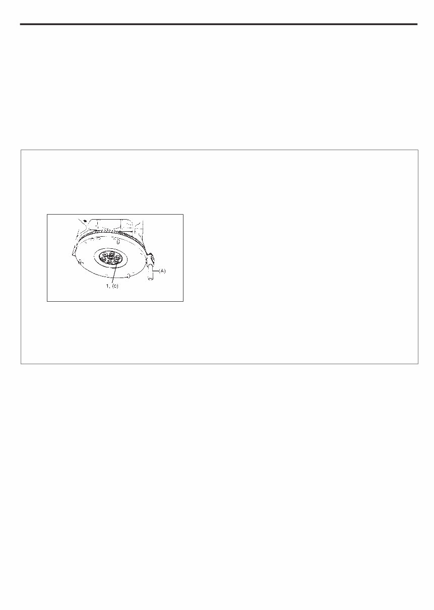
6) Install oil pump. Refer to “Oil pump”.
7) Install flywheel (for M/T vehicle) or drive plate (for A/T vehicle).
Using special tool, lock flywheel or drive plate, and tighten
flywheel or drive plate bolts to specified torque.
Special Tool
(A): 09924-17810
Tightening Torque
(c): 78 N
.
m (7.8 kg-m, 56.0 lb-ft)
1. Flywheel bolts or drive plate bolts for A/T vehicle
4) A number of abbreviations are used in the text.
For their full explanations, refer to “ABBREVIATIONS MAY BE
USED IN THIS MANUAL” of this section.
5) The SI, metric and foot-pound systems are used as units in this
manual.
6) DIAGNOSIS are included in each section as necessary.
7) At the end of each section, there are descriptions of SPECIAL
TOOLS, REQUIRED SERVICE MATERIALS and TIGHT-
ENING TORQUE SPECIFICATIONS that should be used for
the servicing work described in that section.
0A-2 GENGERAL INFORMATION
PRECAUTIONS
GENERAL PRECAUTIONS
The WARNING and CAUTION below describe some general precautions that you should observe when servicing
a vehicle. These general precautions apply to many of the service procedures described in this manual, and they
will not necessarily be repeated with each procedure to which they apply.
WARNING:
D Whenever raising a vehicle for service, be sure to follow the instructions under “VEHICLE LIFTING
POINTS” on SECTION 0A.
D When it is necessary to do service work with the engine running, make sure that the parking brake
is set fully and the transmission is in Neutral (for manual transmission vehicles) or Park (for auto-
matic transmission vehicles), Keep hands, hair, clothing, tools, etc. away from the fan and belts
when the engine is running.
D When it is necessary to run the engine indoors, make sure that the exhaust gas is forced outdoors.
D Do not perform service work in areas where combustible materials can come in contact with a hot
exhaust system. When working with toxic or flammable materials (such as gasoline and refriger-
ant), make sure that the area you work in is well-ventilated.
D To avoid getting burned, keep away from hot metal parts such as the radiator, exhaust manifold,
tailpipe, muffler, etc.
D New and used engine oil can be hazardous. Children and pets may be harmed by swallowing new
or used oil. Keep new and used oil and used engine oil filters away from children and pets.
Continuous contact with used engine oil has been found to cause [skin] cancer in laboratory ani-
mals. Brief contact with used oil may irritate skin. To minimize your exposure to used engine oil,
wear a long-sleeve shirt and moisture-proof gloves (such as dish washing gloves) when changing
engine oil. If engine oil contacts your skin, wash thoroughly with soap and water. Launder any
clothing or rags if wet with oil, recycle or properly dispose of used oil and filters.
D Make sure the bonnet is fully closed and latched before driving. If it is not, it can fly up unexpectedly
during driving, obstructing your view and resulting in an accident.
CAUTION:
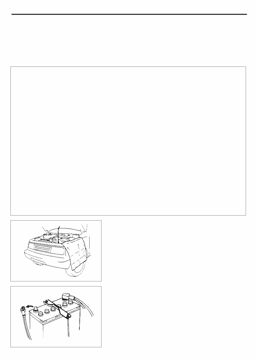
D Before starting any service work, cover fenders, seats and
any other parts that are likely to get scratched or stained
during servicing. Also, be aware that what you wear (e.g,
buttons) may cause damage to the vehicle’s finish.
D When performing service to electrical parts that does not
require use of battery power, disconnect the negative cable
of the battery.
GENERAL INFORMATION 0A-3
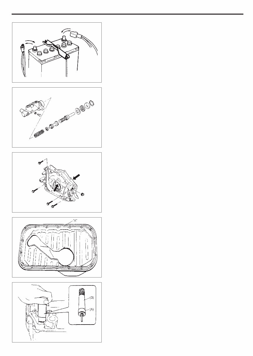
D When removing the battery, be sure to disconnect the nega-
tive cable first and then the positive cable. When reconnect-
ing the battery, connect the positive cable first and then the
negative cable, and replace the terminal cover.
D When removing parts that are to be reused, be sure to keep
them arranged in an orderly manner so that they may be re-
installed in the proper order and position.
D Whenever you use oil seals, gaskets, packing, O-rings,
locking washers, split pins, self-locking nuts, and certain
other parts as specified, be sure to use new ones. Also, be-
fore installing new gaskets, packing, etc., be sure to remove
any residual material from the mating surfaces.
D Make sure that all parts used in reassembly are perfectly
clean.
D When use of a certain type of lubricant, bond or sealant is
specified, be sure to use the specified type.
“A”: Sealant 99000-31150
D Be sure to use special tools when instructed.
Special Tool
(A): 09917-98221
(B): 09916-58210
0A-4 GENGERAL INFORMATION
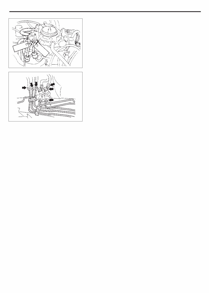
D When disconnecting vacuum hoses, attach a tag describ-
ing the correct installation positions so that the hoses can
be reinstalled correctly.
D After servicing fuel, oil, coolant, vacuum, exhaust or brake
systems, check all lines related to the system for leaks.
D For vehicles equipped with fuel injection systems, never
disconnect the fuel line between the fuel pump and injector
without first releasing the fuel pressure, or fuel can be
sprayed out under pressure.
PRECAUTIONS FOR CATALYTIC CONVERT-
ER
For vehicles equipped with a catalytic converter, use only un-
leaded gasoline and be careful not to let a large amount of un-
burned gasoline enter the converter or it can be damaged.
– Conduct a spark jump test only when necessary, make it as
short as possible, and do not open the throttle.
– Conduct engine compression checks within the shortest
possible time.
– Avoid situations which can result in engine misfire (e.g.
starting the engine when the fuel tank is nearly empty.)
GENERAL INFORMATION 0A-5
PRECAUTIONS FOR ELECTRICAL CIRCUIT
SERVICE
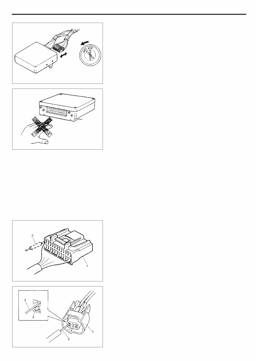
D When disconnecting and connecting coupler, make sure to
turn ignition switch OFF, or electronic parts may get dam-
aged.
D Be careful not to touch the electrical terminals of parts
which use microcomputers (e.g. electronic control unit like
as ECM, PCM, P/S controller, etc.). The static electricity
from your body can damage these parts.
D Never connect any tester (voltmeter, ohmmeter, or whatev-
er) to electronic control unit when its coupler is discon-
nected. Attempt to do it may cause damage to it.
D Never connect an ohmmeter to electronic control unit with
its coupler connected to it. Attempt to do it may cause dam-
age to electronic control unit and sensors.
D Be sure to use a specified voltmeter/ohmmeter. Otherwise,
accurate measurements may not be obtained or personal
injury may result. If not specified, use a voltmeter with high-
impedance (MW/V minimum) or a digital type voltmeter.
D When taking measurements at electrical connectors using
a tester probe (2), be sure to insert the probe from the wire
harness side (backside) of the connector (1).
D When connecting meter probe (2) from terminal side of cou-
pler (1) because it can’t be connected from harness side,
use extra care not to bend male terminal of coupler of force
its female terminal open for connection.
In case of such coupler as shown connect probe as shown
to avoid opening female terminal.
Never connect probe where (3) male terminal is supposed
to fit.
0A-6 GENGERAL INFORMATION
D When checking connection of terminals, check its male half
for bend and female half for excessive opening and both for
locking (looseness), corrosion, dust, etc.
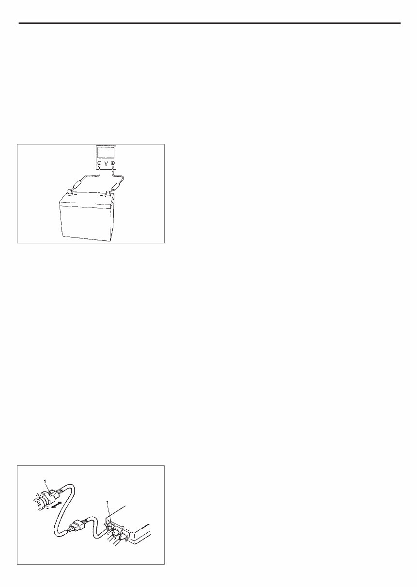
D Before measuring voltage to check for electrical system,
check to make sure that battery voltage is 11V or higher.
Such terminal voltage check at low battery voltage will lead
to erroneous diagnosis.
ELECTRICAL CIRCUIT INSPECTION
PROCEDURE
While there are various electrical circuit inspection methods, de-
scribed here is a general method to check its open and short circuit
by using an ohmmeter and a voltmeter.
OPEN CIRCUIT CHECK
Possible causes for the open circuit are as follows. As the cause
is in the connector or terminal in many cases, they need to be
checked particularly carefully.
D Loose connection of connector
D Poor contact of terminal (due to dirt, corrosion or rust on it, poor
contact tension, entry of foreign object etc.)
D Wire harness being open
When checking system circuits including an electronic control unit
such as ECM, TCM, ABS control module, etc., it is important to per-
form careful check, starting with items which are easier to check.
1) Disconnect negative cable from battery.
2) Check each connector at both ends of the circuit being checked
for loose connection. Also check lock condition of connector if
equipped with connector lock.
1. Check for loose connection
Sensor
ECM
GENERAL INFORMATION 0A-7
You're Reading a Preview
What's Included?
Fast Download Speeds
Online & Offline Access
Access PDF Contents & Bookmarks
Full Search Facility
Print one or all pages of your manual
$41.99
Viewed 89 Times Today


Secure transaction
What's Included?
Fast Download Speeds
Online & Offline Access
Access PDF Contents & Bookmarks
Full Search Facility
Print one or all pages of your manual
$41.99
- The SUZUKI MARUTI 800 ALTO MB308 WORKSHOP FACTORY SERVICE REPAIR MANUAL is a comprehensive guide designed to assist in diagnosing, maintaining, adjusting, and performing minor service operations on the vehicle.
- It provides detailed instructions for replacing components (Service) and disassembling and assembling major components (Unit Repair-Overhaul).
- Specifically tailored for the MB308 model, the manual covers a wide range of topics to ensure optimal vehicle performance.
- The General Information section provides essential details about the vehicle, while the Maintenance and Lubrication section offers guidance on keeping the vehicle in top condition.
- The Heating and Air Conditioning section provides instructions on managing the heater, ventilation, and air conditioning systems, if equipped.
- The Steering, Suspension, Wheels, and Tires section covers topics such as front end alignment, manual rack and pinion steering, front and rear suspension (both leaf spring and coil spring types), as well as wheels and tires.
- The Drive Shaft and Propeller Shaft section offers guidance on the front drive shaft, while the Brake System section provides detailed instructions on maintaining and servicing the vehicle's brakes.
- The Engine section is divided into Engine Diagnosis, Engine Mechanical (F8B Engine), Engine Mechanical (F8D Engine), Engine Cooling, Engine Fuel, and Engine and Emission Control System subsections.
- These sections provide comprehensive information on diagnosing engine issues, maintaining engine components, managing engine cooling and fuel systems, as well as controlling emissions.
- The Transmission, Clutch, and Differential section covers manual transmissions (both 4-speed and 5-speed) and provides guidance on maintaining and servicing the clutch system.
- The Electrical System section offers detailed information on the vehicle's electrical components, while the Wiring Diagram section provides visual aids for easy reference.
- Lastly, the Body Service and Restraint System sections provide instructions on servicing the vehicle's body and restraint systems, ensuring safety and comfort.
- With this SUZUKI MARUTI 800 ALTO MB308 WORKSHOP FACTORY SERVICE REPAIR MANUAL, all the necessary information is available to keep the vehicle running smoothly.
- It is a valuable resource for both professional mechanics and DIY enthusiasts.


