

2004-2012 Suzuki APV Van Service & Repair Manual
What's Included?
Fast Download Speeds
Online & Offline Access
Access PDF Contents & Bookmarks
Full Search Facility
Print one or all pages of your manual

GENERAL INFORMATION 0A-1
0A
SECTION 0A
GENERAL INFORMATION
CONTENTS
How To Use This Manual ................................ 0A-2
Precautions...................................................... 0A-3
Precaution for Vehicle Equipped with a
Supplemental Restraint (Air Bag) System..... 0A-3
Diagnosis................................................... 0A-3
Service and Handling ................................ 0A-4
General Precautions ..................................... 0A-6
Precautions for Catalytic Converter............... 0A-9
Precaution for Installing Mobile
Communication Equipment ........................... 0A-9
Precautions for Vehicle Hooks ...................... 0A-9
Precautions for Electrical Circuit Service .... 0A-10
Electrical Circuit Inspection Procedure........ 0A-12
Intermittent and Poor Connection ............... 0A-15
Identification Information ............................. 0A-17
Vehicle Identification Number ..................... 0A-17
Engine Identification Number ...................... 0A-17
Transmission Identification Number ............ 0A-17
Warning, Caution and Information Labels.. 0A-18
Vehicle Lifting Points ................................... 0A-19
Abbreviations and Symbols May Be Used
In This Manual ............................................... 0A-21
Fastener Information .................................... 0A-24
Metric Fasteners ......................................... 0A-24
Fastener Strength Identification .................. 0A-24
Standard Tightening Torque ....................... 0A-24
0A-2 GENERAL INFORMATION
How To Use This Manual
1) There is a “TABLE OF CONTENTS” for the whole manual on the third page of this manual, whereby you can
easily find the section that offers the information you need. Also, there is a “CONTENTS” on the first page of
each section, where the main items in that section are listed.
2) Each section of this manual has its own pagination. It is indicated at the top of each page along with the sec-
tion name.
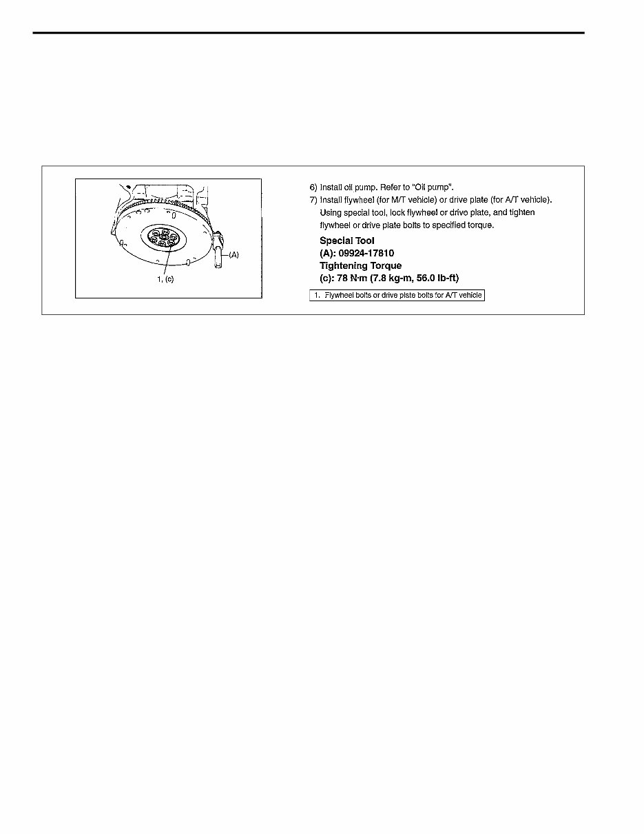
3) The special tool usage and torque specification are given as shown in figure below.
4) A number of abbreviations are used in the text.
For their full explanations, refer to “Abbreviations and Symbols May Be Used In This Manual” of this section.
5) The SI, metric and foot-pound systems are used as units in this manual.
6) “Diagnosis” are included in each section as necessary.
7) At the end of each section, there are descriptions of “Special Tool”, “Required Service Material” and “Tight-
ening Torque Specification” that should be used for the servicing work described in that section.
GENERAL INFORMATION 0A-3
Precautions
Precaution for Vehicle Equipped with a
Supplemental Restraint (Air Bag) System
Diagnosis
• When trouble shooting air bag system, be sure to follow
“Diagnosis” in Section 10B. Bypassing these procedures
may result in extended diagnostic time, incorrect diagnosis,
and incorrect parts replacements.
• Never use electrical test equipment other than that specified
in this manual.
WARNING:
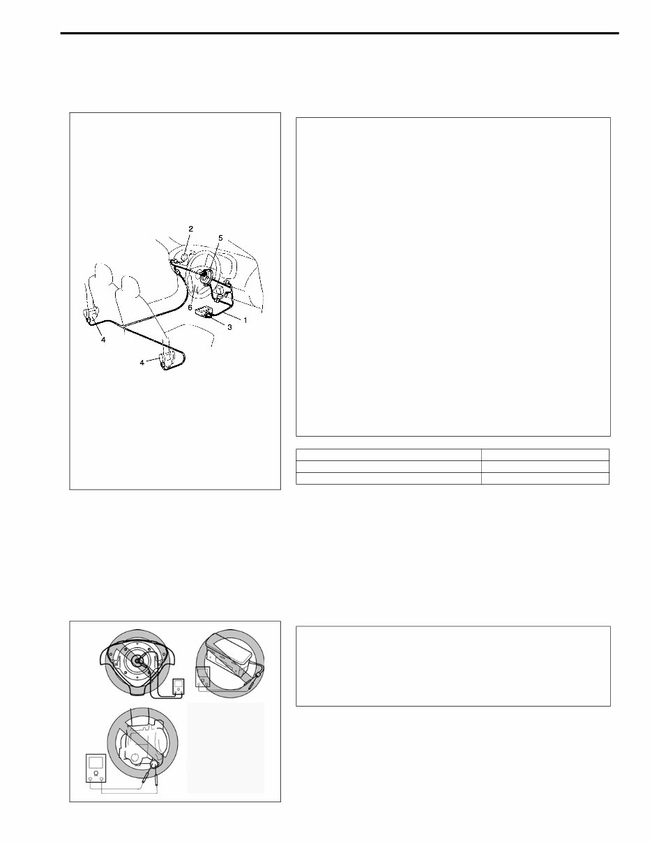
• The configuration of air bag system parts are shown in
the figure. When it is necessary to service (remove,
reinstall and inspect) these parts, be sure to follow
procedures described in Section 10B. Failure to follow
proper procedures could result in possible air bag sys-
tem activation, personal injury, damage to parts or air
bag system being unable to activate when necessary.
• If the air bag system and another vehicle system both
need repair, SUZUKI recommends that the air bag sys-
tem be repaired first, to help avoid unintended air bag
system activation.
• Do not modify the steering wheel, dashboard, or any
other air bag system components. Modifications can
adversely affect air bag system performance and lead
to injury.
• If the vehicle will be exposed to temperature over 93°C
(200°F) (For example, during a pint baking process),
remove the air bag system components beforehand to
avoid component damage or unintended air bag sys-
tem activation.
1. Air bag wire harness (in main and floor harness) 4. Seat belt pretensioner
2. Passenger air bag (inflator) module 5. Contact coil
3. SDM 6. Driver air bag (inflator) module
WARNING:
Never attempt to measure the resistance of the air bag
(inflator) modules (driver and passenger). It is very dan-
gerous as the electric current from the tester may deploy
the air bag or activate the pretensioner.
0A-4 GENERAL INFORMATION
Service and Handling
WARNING:
Many of service procedures require disconnection of
“Air Bag” fuse and all air bag (inflator) module (s) from
initiator circuit to avoid an accidental deployment.
Driver and passenger Air Bag (Inflator) Modules
• For handling and storage of a live air bag (inflator)
module, select a place where the ambient temperature
below 65°C (150°F), without high humidity and away
from electric noise.
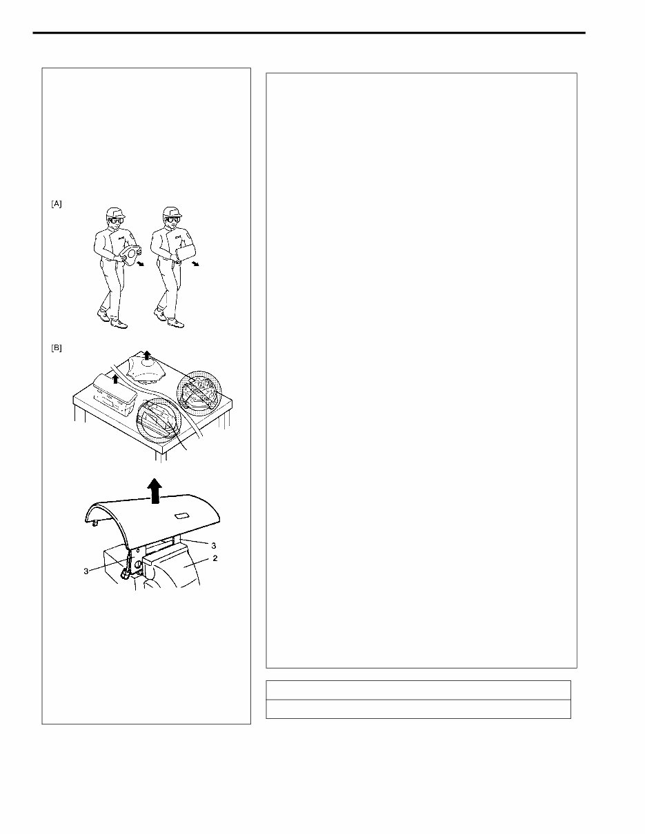
• When carrying a live air bag (inflator) module, make
sure the bag opening is pointed away from you. In
case of an accidental deployment, the bag will then
deploy with minimal chance of injury. Never carry the
air bag (inflator) module by the wires or connector on
the underside of the module. When placing a live air
bag (inflator) module on a bench or other surface,
always face the bag up, away from the surface. As the
live passenger air bag (inflator) module must be placed
with its bag (trim cover) facing up, place it on the work-
bench with a slit (1) or use the workbench vise (2) to
hold it securely at its lower mounting bracket (3). It is
also prohibited to place anything on top of the trim
cover and stack air bag (inflator) modules. This is nec-
essary so that a free space is provided to allow the air
bag to expand in the unlikely event of accidental
deployment. Otherwise, personal injury may result.
• Never dispose of live (undeployed) air bag (inflator)
modules (driver and passenger). If disposal is neces-
sary, be sure to deploy them according to deployment
procedures described in Section 10B before disposal.
• The air bag (inflator) module immediately after deploy-
ment is very hot. Wait for at least half an hour to cool it
off before proceeding the work.
• After an air bag (inflator) module has been deployed,
the surface of the air bag may contain a powdery resi-
due. This powder consists primarily of cornstarch
(used to lubricate the bag as it inflates) and by-prod-
ucts of the chemical reaction. As with many service
procedures, gloves and safety glasses should be
worn.
[A] : Always carry air bag (inflator) module with trim cover (air bag opening) away from
body.
[B] : Always place air bag (inflator) module on workbench with trim cover (air bag open-
ing) up, away from loose objects.
GENERAL INFORMATION 0A-5
• Even when the accident was light enough not to cause air bags to activate, be sure to inspect sys-
tem parts and other related parts according to instructions under “Repair and Inspection Required
After an Accident” in Section 10B.
• When servicing parts other than air bag system, if shocks may be applied to air bag system compo-
nent parts, remove those parts beforehand.
• When handling the air bag (inflator) modules (driver and passenger), seat belt pretensioner (driver
and passenger) or SDM, be careful not to drop it or apply an impact to it. If an excessive impact was
applied, never attempt disassembly or repair but replace it with a new one.
• When grease, cleaning agent, oil, water, etc. has got onto air bag (inflator) modules (driver and pas-
senger) or seat belt pretensioner (drive and passenger), wipe off immediately with a dry cloth.
• Air bag wire harness is included in floor and main wire harnesses. Air bag wire harness branched off
from floor and main wire harnesses can be identified easily as it is covered with a yellow protection
tube and it has yellow connectors. Be very careful when handling it.
• When an open in air bag wire harness, damaged wire harness, connector or terminal is found,
replace wire harness, connectors and terminals as an assembly.
WARNING:
Sensing and Diagnostic Module (SDM)
• For handling and storage of a SDM, select a place where the ambient temperature below 65°C
(150°F), without high humidity and away from electric noise.
• During service procedures, be very careful when handling a SDM. Never strike or jar the SDM.
• Never power up the air bag system when the SDM is not rigidly attached to the vehicle. All SDM and
mounting bracket fasteners must be carefully torqued and the arrow must be pointing toward the
front of the vehicle to ensure proper operation of the air bag system.
The SDM could be activated when powered while not rigidly attached to the vehicle which could
cause deployment and result in personal injury.
WARNING:
Driver and Passenger Seat Belt Pretensioner
(If equipped)
• For handling and storage of a live seat belt preten-
sioner, select a place where the ambient temperature
below 65°C (150°F), without high humidity and away
from electric noise.
• Never carry seat belt pretensioner by wire or connec-
tor of pretensioner. When placing a live seat belt pre-
tensioner on the workbench or some place like that,
never put something on seat belt pretensioner. Other-
wise, personal injury may result.
• Never dispose of live (inactivated) seat belt preten-
sioner (drive and passenger). If disposal is necessary,
be sure to activate them according to activation proce-
dures described in Section 10B before disposal.
• The seat belt pretensioner immediately after activation
is very hot. Wait for at least half an hour to cool it off
before proceeding the work.
With many service procedures, gloves and safety
glasses should be worn to prevent any possible irritation
of the skin or eyes.

0A-6 GENERAL INFORMATION
• Do not apply power to the air bag system unless all components are connected or a diagnostic chart
requests it, as this will set a diagnostic trouble code.
• Never use air bag system component parts from another vehicle.
• When using electric welding, be sure to disconnect all air bag (inflator) module connectors and pre-
tensioner connectors from air bag wire harness respectively.
• Never expose air bag system component parts directly to hot air (drying or baking the vehicle after
painting) or flames.
• WARNING / CAUTION labels are attached on each part of air bag system components. Be sure to fol-
low the instructions.
• After vehicle is completely repaired, perform “Air Bag Diagnostic System Check” in Section 10B.
General Precautions
The WARNING and CAUTION below describe some general precautions that you should observe when servic-
ing a vehicle. These general precautions apply to many of the service procedures described in this manual, and
they will not necessarily be repeated with each procedure to which they apply.
• Before starting any service work, cover fenders, seats
and any other parts that are likely to get scratched or
stained during servicing. Also, be aware that what you
wear (e.g, buttons) may cause damage to the vehicle's
finish.
WARNING:
• Whenever raising a vehicle for service, be sure to follow the instructions under “Vehicle Lifting
Points” in this section.
• When it is necessary to do service work with the engine running, make sure that the parking brake
is set fully and the transmission is in Neutral (for manual transmission vehicles) or Park (for auto-
matic transmission vehicles). Keep hands, hair, clothing, tools, etc. away from the fan and belts
when the engine is running
• When it is necessary to run the engine indoors, make sure that the exhaust gas is forced outdoors.
• Do not perform service work in areas where combustible materials can come in contact with a hot
exhaust system. When working with toxic or flammable materials (such as gasoline and refriger-
ant), make sure that the area you work in is well-ventilated.
• To avoid getting burned, keep away from hot metal parts such as the radiator, exhaust manifold,
tailpipe, muffler, etc.
• New and used engine oil can be hazardous. Children and pets may be harmed by swallowing new or
used oil. Keep new and used oil and used engine oil filters away from children and pets.
Continuous contact with used engine oil has been found to cause [skin] cancer in laboratory ani-
mals. Brief contact with used oil may irritate skin. To minimize your exposure to used engine oil,
wear a long-sleeve shirt and moisture-proof gloves (such as dish washing gloves) when changing
engine oil.
If engine oil contacts your skin, wash thoroughly with soap and water. Launder any clothing or rags
if wet with oil, recycle or properly dispose of used oil and filters.
• Make sure the bonnet is fully closed and latched before driving. If it is not, it can fly up unexpect-
edly during driving, obstructing your view and resulting in an accident.
GENERAL INFORMATION 0A-7
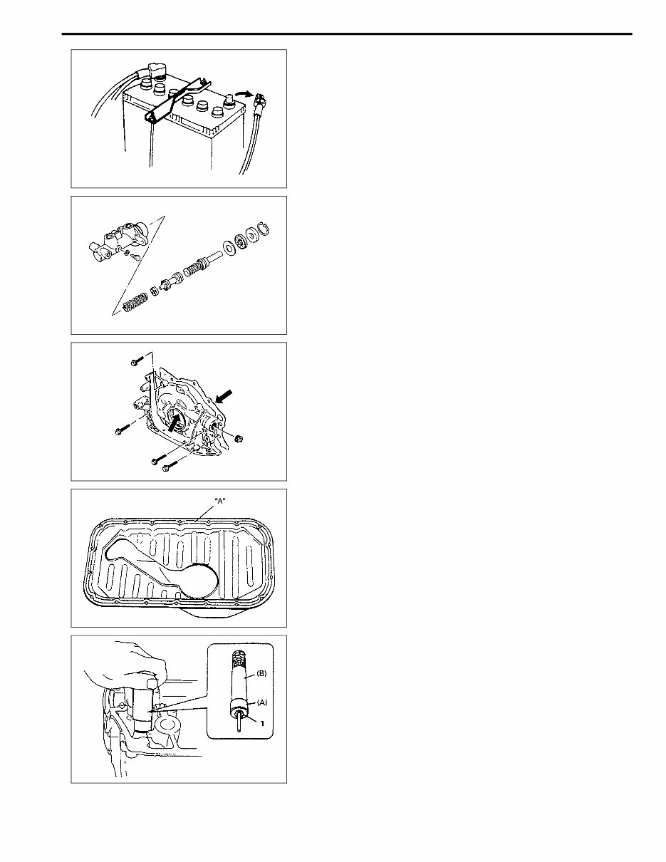
• When performing service to electrical parts that does
not require use of battery power, disconnect the nega-
tive cable of the battery.
• Before disconnecting the negative cable from battery,
record display of the clock and/or audio system (if
equipped), and reset it as before after connecting.
• When removing parts that are to be reused, be sure to
keep them arranged in an orderly manner so that they
may be reinstalled in the proper order and position.
• Whenever you use oil seals, gaskets, packing, O-rings,
locking washers, split pins, self-locking nuts, and cer-
tain other parts as specified, be sure to use new ones.
Also, before installing new gaskets, packing, etc., be
sure to remove any residual material from the mating
surfaces.
• Make sure that all parts used in reassembly are perfectly
clean.
• When use of a certain type of lubricant, bond or sealant
is specified, be sure to use the specified type.
“A”: Sealant 99000-31150
• Be sure to use special tools when instructed.
Special tool
(A): 09917-98221
(B): 09916-58210
0A-8 GENERAL INFORMATION
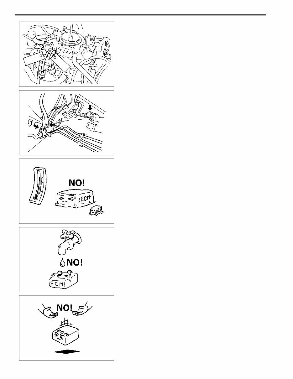
• When disconnecting vacuum hoses, attach a tag
describing the correct installation positions so that the
hoses can be reinstalled correctly.
• After servicing fuel, oil, coolant, vacuum, exhaust or
brake systems, check all lines related to the system for
leaks.
• For vehicles equipped with fuel injection systems, never
disconnect the fuel line between the fuel pump and
injector without first releasing the fuel pressure, or fuel
can be sprayed out under pressure.
• When performing a work that produces a heat exceeding
80°C (176°F) in the vicinity of the electrical parts, remove
the heat sensitive electrical part(s) beforehand.
• Use care not to expose connectors and electrical parts
to water which will be a cause of a trouble.
• Always be careful not to handle electrical parts (com-
puter, relay, etc.) in a rough manner or drop them.
GENERAL INFORMATION 0A-9
Precautions for Catalytic Converter
For vehicles equipped with a catalytic converter, use only unleaded gasoline and be careful not to let a
large amount of unburned gasoline enter the converter or it can be damaged.
• Conduct a spark jump test only when necessary, make it as short as possible, and do not open the
throttle.
• Conduct engine compression checks within the shortest possible time.
• Avoid situations which can result in engine misfire (e.g. starting the engine when the fuel tank is
nearly empty.)
Precaution for Installing Mobile Communication Equipment
When installing mobile communication equipment such as CB (Citizens-Band) -radio or cellular-tele-
phone, be sure to observe the following precautions.
Failure to follow cautions may adversely affect electronic control system.
• Keep the antenna as far away as possible from the vehicle’s electronic control unit.
• Keep the antenna feeder more than 20 cm (7.9 in) away from electronic control unit and its wire har-
nesses.
• Do not run the antenna feeder parallel with other wire harnesses.
• Confirm that the antenna and feeder are correctly adjusted.
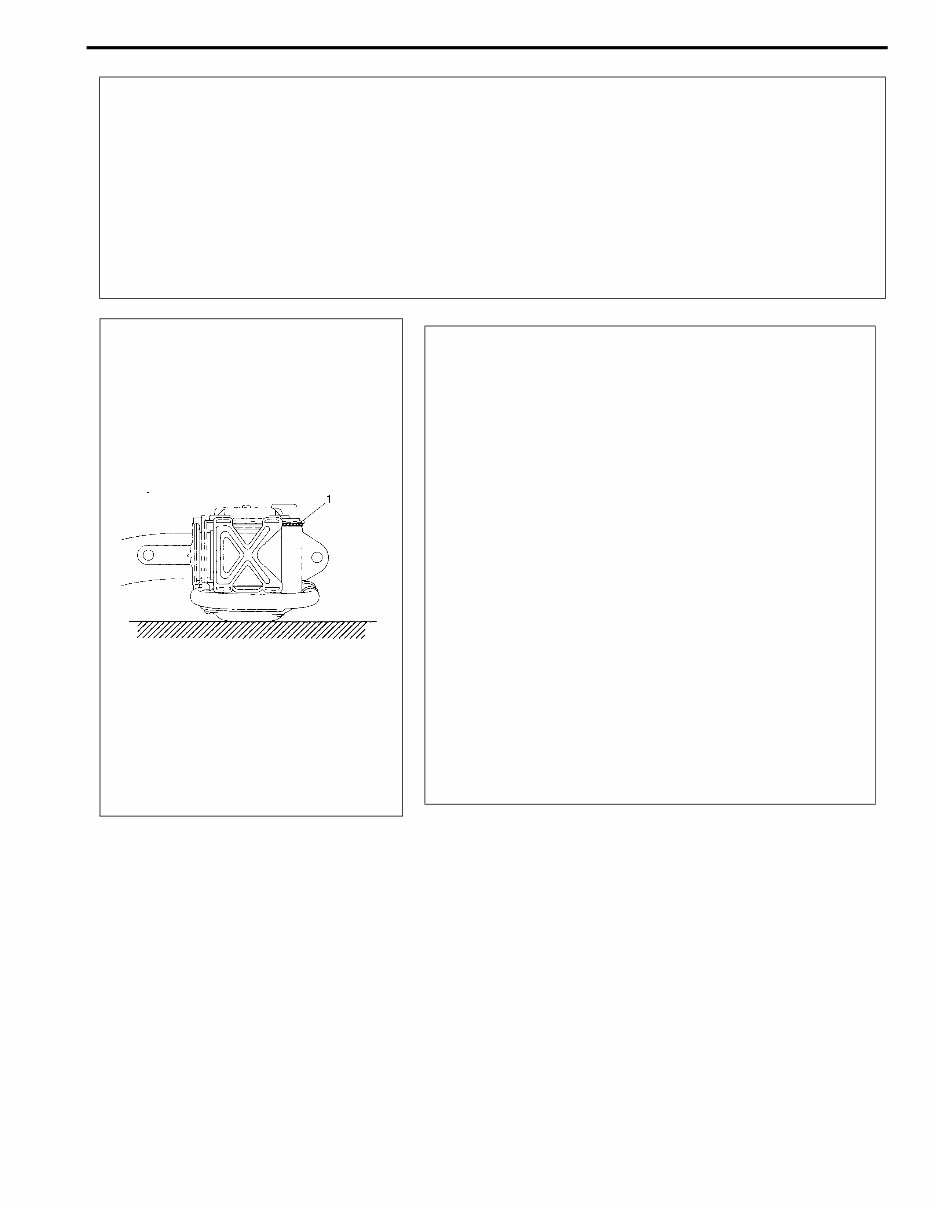
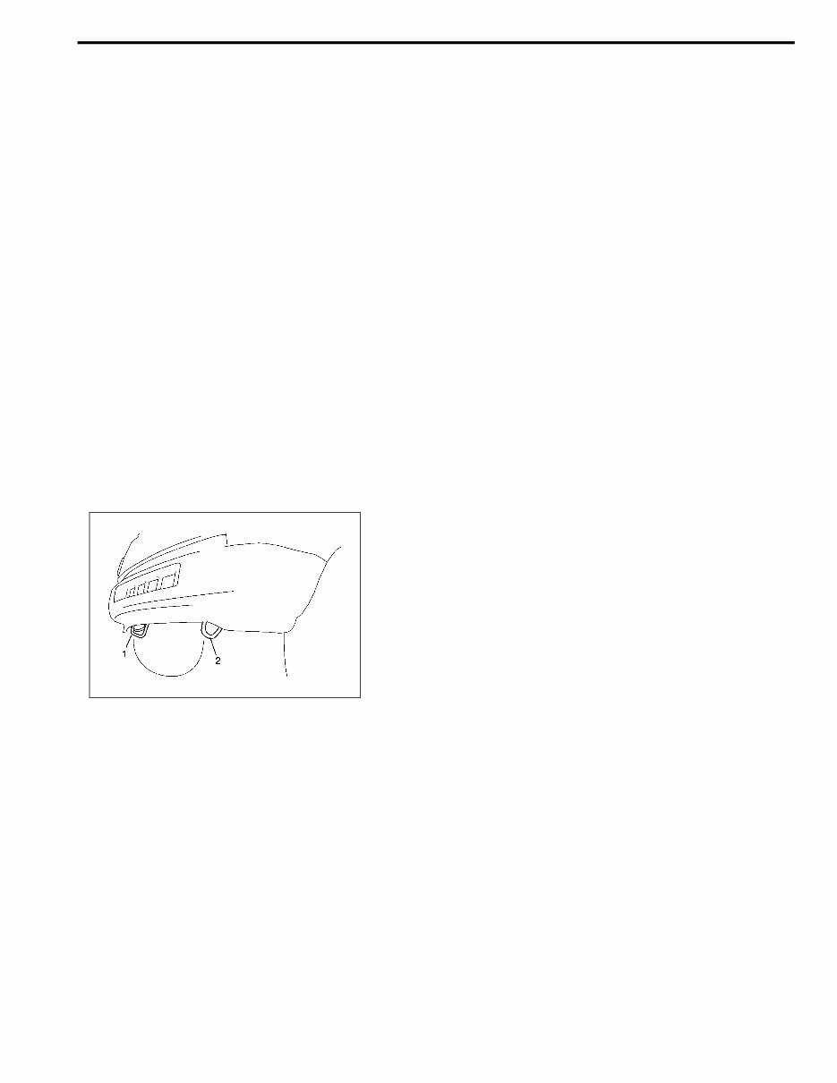
Precautions for Vehicle Hooks
Never use hook (2) to tow (or to be towed by) another vehicle
on the road or highway or body may be deformed.
Use hook (1) for towing purpose.
When vehicle is shipped by sea and land, use hooks (1) and
(2) to tie-down vehicle.
0A-10 GENERAL INFORMATION
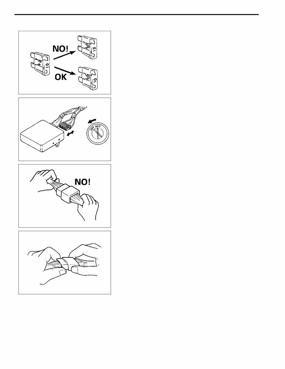
Precautions for Electrical Circuit Service
• When replacing a fuse, make sure to use a fuse of the
specified capacity. Use of a fuse with a larger capacity
will cause a damage to the electrical parts and a fire.
• When disconnecting and connecting coupler, make sure
to turn ignition switch OFF, or electronic parts may get
damaged.
• When disconnecting connector, never pull the wiring
harness. Unlock the connector lock first and then pull
them apart by holding connectors themselves
• When connecting connectors, also hold connectors and
put them together until they lock securely (a click is
heard).
You're Reading a Preview
What's Included?
Fast Download Speeds
Online & Offline Access
Access PDF Contents & Bookmarks
Full Search Facility
Print one or all pages of your manual
$39.99
Viewed 94 Times Today


Secure transaction
What's Included?
Fast Download Speeds
Online & Offline Access
Access PDF Contents & Bookmarks
Full Search Facility
Print one or all pages of your manual
$39.99
- This complete factory service repair workshop manual is available for instant access on your computer, tablet, or smartphone.
- It covers all repairs, servicing, and troubleshooting procedures with detailed photos, diagrams, step-by-step instructions, and highly detailed exploded diagrams and pictures.
- Professional mechanics and technicians use this manual for completing every job correctly.
- You have the option to print out a single page or the entire manual.
- This manual can be used on multiple computers without any limitations or trial periods.
- There is no expiry date, renewal fee, or need to pay any extra for continued use.
- It is fully compatible with all Windows and MAC computers.
Thanks for considering this item. Please click on the button for more information.


