IMPORTANT WARNING/CAUTION/NOTE Please read this manual and follow its instructions carefully. To emphasize special information, the words WARNING, CAUTION and NOTE have special meanings. Pay special attention to the messages highlighted by these signal words. WARNING: Indicates a potential hazard that could result in death or injury. CAUTION: Indicates a potential hazard that could result in vehicle damage. NOTE: Indicates special information to make maintenance easier or instructions clearer. WARNING: This service manual is intended for authorized Suzuki dealers and qualified service mechanics only. Inexperienced mechanics or mechanics without the proper tools and equipment may not be able to properly perform the services described in this manual. Improper repair may result in injury to the mechanic and may render the vehicle unsafe for the driver and passengers. WARNING: For vehicles equipped with a Supplemental Restraint (Air Bag) System: • Service on and around the air bag system components or wiring must be performed only by an authorized SUZUKI dealer. Refer to “Air Bag System Components and Wiring Location View” under “General Description” in air bag system section in order to confirm whether you are performing ser- vice on or near the air bag system components or wiring. Please observe all WARNINGS and “Ser- vice Precautions” under “On-Vehicle Service” in air bag system section before performing service on or around the air bag system components or wiring. Failure to follow WARNINGS could result in unintentional activation of the system or could render the system inoperative. Either of these two conditions may result in severe injury. • If the air bag system and another vehicle system both need repair, Suzuki recommends that the air bag system be repaired first, to help avoid unintended air bag system activation. • Do not modify the steering wheel, instrument panel or any other air bag system component (on or around air bag system components or wiring). Modifications can adversely affect air bag system performance and lead to injury. • If the vehicle will be exposed to temperatures over 93°C (200°F) (for example, during a paint baking process), remove the air bag system components (air bag (inflator) modules, SDM and/or seat belt with pretensioner) beforehand to avoid component damage or unintended activation.
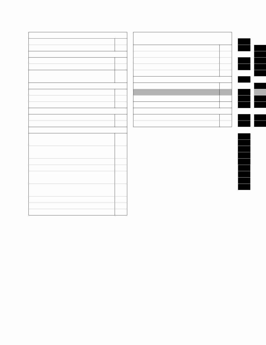
TABLE OF CONTENTS GENERAL INFORMATION TRANSAXLE, CLUTCH AND DIFFERENTIAL General Information 0A 0A Maintenance and Lubrication 0B Manual Transaxle 7A1 0B 7A1 HEATING AND AIR CONDITIONING Automatic Transaxle (4 A/T) 7B1 7B1 Heater and Ventilation 1A Clutch 7C1 1A 7C1 Air Conditioning (Optional) 1B Transfer 7D 1B 7D STEERING, SUSPENSION, WHEELS AND TIRES 3 Rear Differential 7F 7F ELECTRICAL SYSTEM 3 DRIVE SHAFT AND PROPELLER SHAFT Body Electrical System 8 8 Front Drive Shaft 4A Wiring Diagram 8A 4A 8A Propeller Shafts 4B Immobilizer Control System (if equipped) 8G 4B 8G Rear Drive Shaft 4C BODY SERVICE 9 4C 9 BRAKE SYSTEM RESTRAINT SYSTEM Brakes 5 Restraint System 10 5 10 Antilock Brake System (ABS) 5B Air Bag System 10B 5B 10B ENGINE Engine General Information and 6 6 Diagnosis (M13/M16 Engines) 6A1 Engine Mechanical 6A1 6B (M13 and M16 Engines) 6C Engine Cooling 6B 6E1 Engine Fuel 6C 6F1 Engine and Emission Control System 6E1 6G (M13/M16 Engines) 6H Ignition System 6F1 6K (Electronic Ignition System) Cranking System 6G Charging System 6H Exhaust System 6K NOTE: The screen toned Section 8A is in Wiring Diagram Manual mentioned in FOREWORD of this manual.
GENERAL INFORMATION 0A-1 0A 6G 6H 6K 7A 7A1 7B1 7C1 7D 7E 7F 8A 8B 8C 8D 8E 9 10 10A 10B SECTION 0A GENERAL INFORMATION CONTENTS How To Use This Manual ................................0A-2 Precautions......................................................0A-3 Precaution for Vehicles Equipped with a Supplemental Restraint (Air Bag) System..... 0A-3 Diagnosis................................................... 0A-3 Servicing and handling .............................. 0A-4 General Precautions ..................................... 0A-6 Precautions for Catalytic Converter............... 0A-9 Precaution for Installing Mobile Communication Equipment ........................... 0A-9 Precaution for Vehicle Tie-Down Hooks...... 0A-10 Precaution in Servicing Full-Time 4WD Vehicle ........................................................ 0A-10 Precautions for Electrical Circuit Service .... 0A-11 Electrical Circuit Inspection Procedure........ 0A-14 Open circuit check ................................... 0A-14 Short circuit check (wire harness to ground) .................................................... 0A-16 Intermittent and Poor Connection ............... 0A-17 Identification Information............................. 0A-19 Vehicle Identification Number ..................... 0A-19 Engine Identification Number ...................... 0A-19 Transmission Identification Number............ 0A-19 Warning, Caution and Information Labels..0A-20 Vehicle Lifting Points ................................... 0A-21 Abbreviations and Symbols May Be Used in This Manual ............................................... 0A-23 Fastener Information .................................... 0A-27 Metric Fasteners ......................................... 0A-27 Fastener Strength Identification .................. 0A-27 Standard Tightening Torque ....................... 0A-27
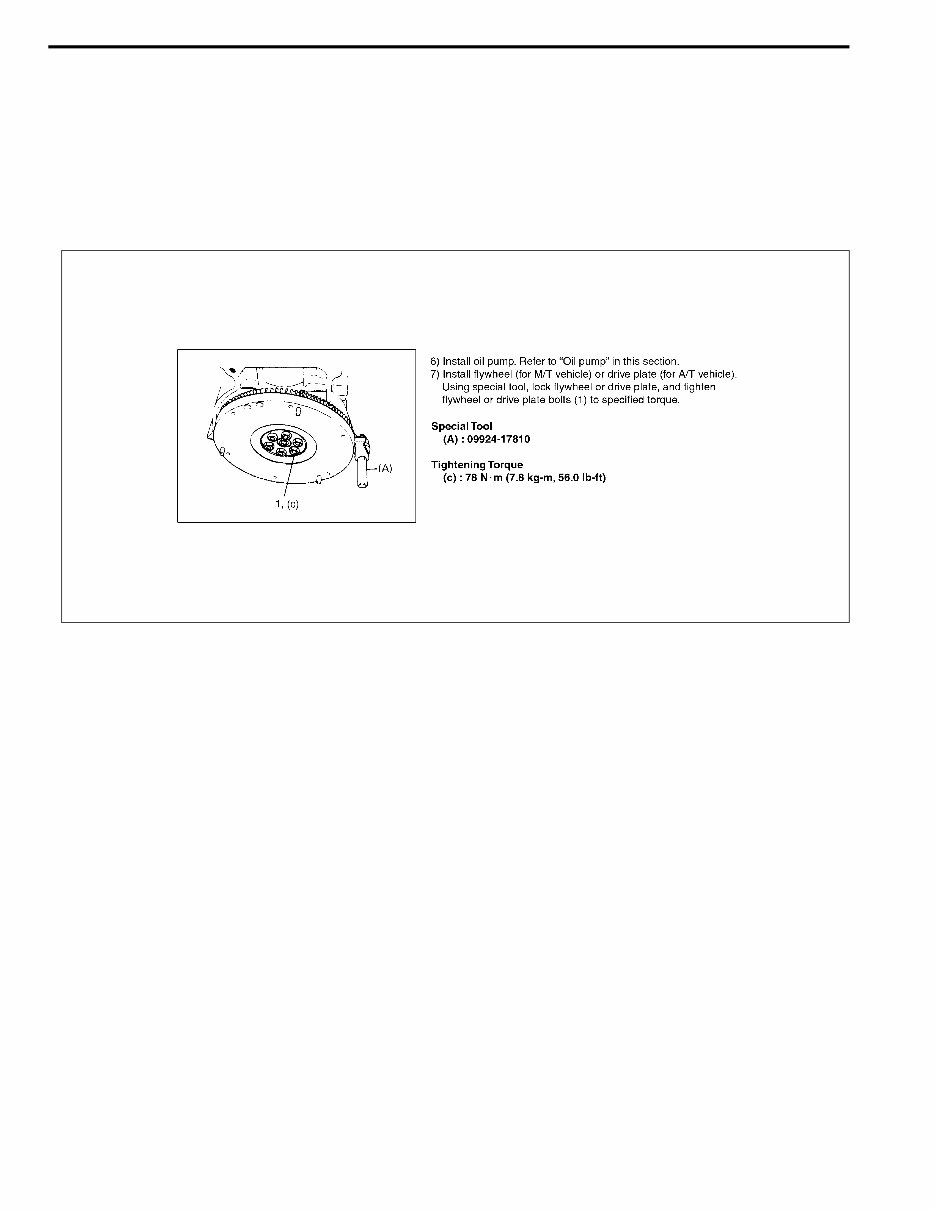
0A-2 GENERAL INFORMATION How To Use This Manual 1) There is a “TABLE OF CONTENTS” on the third page of this manual, whereby you can easily find the sec- tion that offers the information you need. Also, there is a CONTENTS on the first page of each section, where the main items in that section are listed. 2) Each section of this manual has its own pagination. It is indicated at the top of each page along with the Sec- tion name. 3) The special tool usage and torque specification are given as shown in the figure. 4) A number of abbreviations and symbols are used in the text.For their full explanations, refer to “ABBREVIA- TIONS AND SYMBOLS MAY BE USED IN THIS MANUAL” in this section. 5) The SI, metric and foot-pound systems are used as units in this manual. 6) “DIAGNOSIS” are included in each section as necessary. 7) At the end of each section, there are descriptions of “SPECIAL TOOL”, “REQUIRED SERVICE MATERIAL” and “TIGHTENING TORQUE SPECIFICATION” that should be used for the servicing work described in that section.
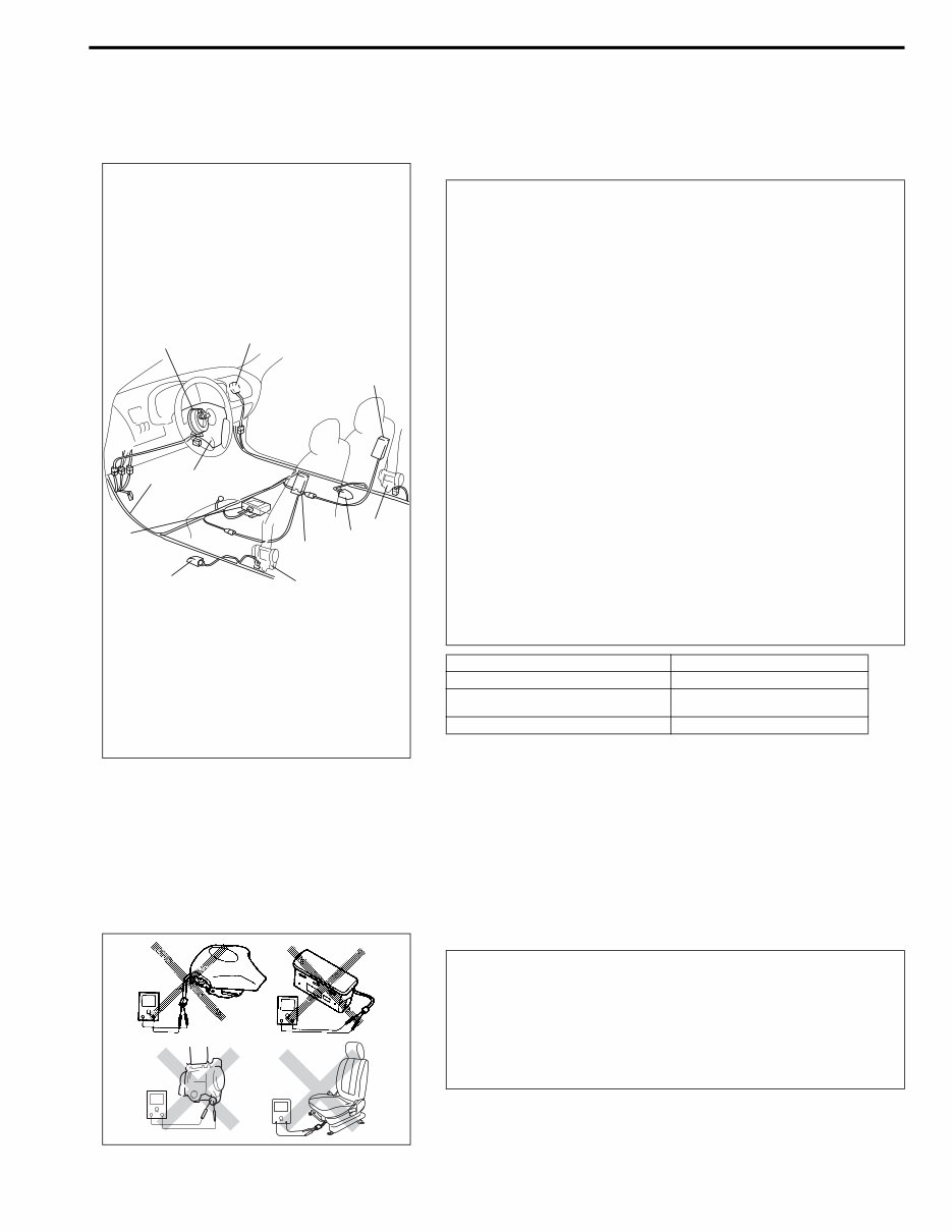
GENERAL INFORMATION 0A-3 Precautions Precaution for Vehicles Equipped with a Sup- plemental Restraint (Air Bag) System Diagnosis • When troubleshooting air bag system, be sure to follow “DIAGNOSIS” in Section 10B. Bypassing these procedures may result in extended diagnostic time, incorrect diagnosis, and incorrect parts replacement. • Never use electrical test equipment other than that specified in this manual. WARNING: • The configuration of air bag system parts are as shown in the figure. When it is necessary to service (remove, reinstall and inspect) these parts, be sure to follow procedures described in Section 10B. Failure to follow proper procedures could result in possible air bag sys- tem activation, personal injury, damage to parts or air bag system being unable to activate when necessary. • If the air bag system and another vehicle system both need repair, SUZUKI recommends that the air bag sys- tem be repaired first, to help avoid unintended air bag system activation. • Do not modify the steering wheel, dashboard, or any other air bag system components. Modifications can adversely affect air bag system performance and lead to injury. • If the vehicle will be exposed to temperatures over 93°C (200°F) (for example, during a paint baking pro- cess), remove the air bag system components before- hand to avoid component damage or unintended air bag system activation. 1. Air bag wire harness (in floor harness) 5. Contact coil 2. Passenger air bag (inflator) module 6. Driver air bag (inflator) module 3. SDM 7. Side air bag (inflator) module (if equipped) 4. Seat belt pretensioner 8. Side sensor (if equipped) 7 4 4 8 7 8 6 2 5 1 3 WARNING: Never attempt to measure the resistance of the air bag (inflator) modules (driver, passenger and side) and seat belt pretensioners (driver and passenger). It is very dan- gerous as the electric current from the tester may deploy the air bag or activate the pretensioner.
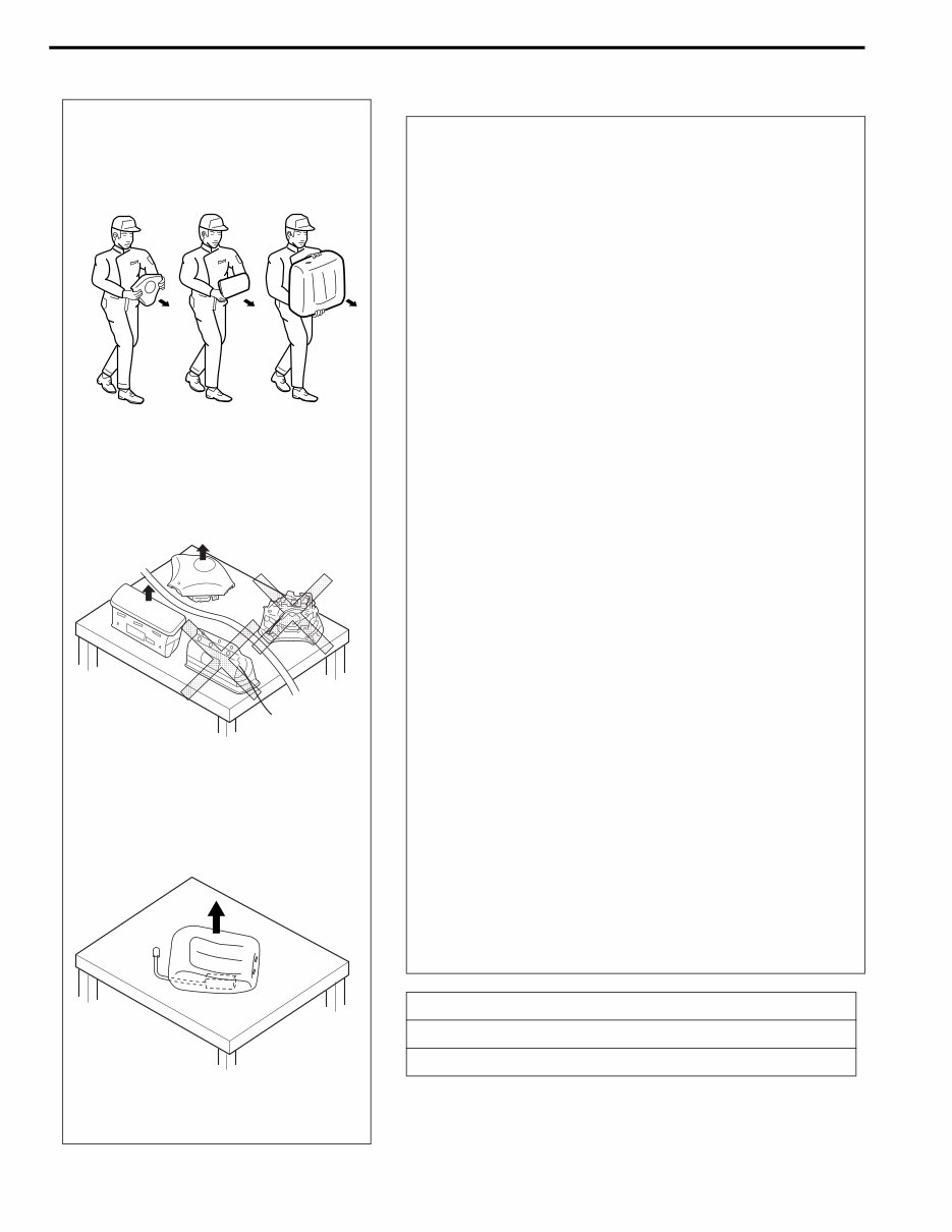
0A-4 GENERAL INFORMATION Servicing and handling WARNING: Many of service procedures require disconnection of “AIR BAG” fuse and all air bag (inflator) module(s) from initiator circuit to avoid an accidental deployment. Driver, Passenger and Side Air Bag (Inflator) Modules • For handling and storage of a live air bag (inflator) module, select a place where the ambient temperature below 65°C (150°F), without high humidity and away from electric noise. • When carrying a live air bag (inflator) module, make sure the bag opening is pointed away from you. In case of an accidental deployment, the bag will then deploy with minimal chance of injury. Never carry the air bag (inflator) module by the wires or connector on the underside of the module. When placing a live air bag (inflator) module on a bench or other surface, always face the bag up, away from the surface. The front seat back with the live air bag (inflator) module must be placed with its frontal seat cover facing up. It is also prohibited to place anything on top of the trim cover and stack air bag (inflator) modules. This is necessary so that a free space is provided to allow the air bag to expand in the unlikely event of accidental deployment. Otherwise, personal injury may result. • Never dispose of live (undeployed) air bag (inflator) modules (driver, passenger and side). If disposal is necessary, be sure to deploy them according to deployment procedures described in Section 10B before disposal. • The air bag (inflator) module immediately after deploy- ment is very hot. Wait for at least half an hour to cool it off before proceeding the work. • After an air bag (inflator) module has been deployed, the surface of the air bag may contain a powdery resi- due. This powder consists primarily of cornstarch (used to lubricate the bag as it inflates) and by-prod- ucts of the chemical reaction. As with many service procedures, gloves and safety glasses should be worn. [A] : ALWAYS CARRY AIR BAG (INFLATOR) MODULE WITH TRIM COVER (AIR BAG OPENING) AWAY FROM BODY. [B] : ALWAYS PLACE AIR BAG (INFLATOR) MODULE ON WORKBENCH WITH TRIM COVER (AIR BAG OPENING) UP, AWAY FROM LOOSE OBJECTS. [C] : ALWAYS PLACE WITH ITS FRONTAL SEAT COVER FACING UP, AWAY FROM LOOSE OBJECTS. [A] [B] [C]
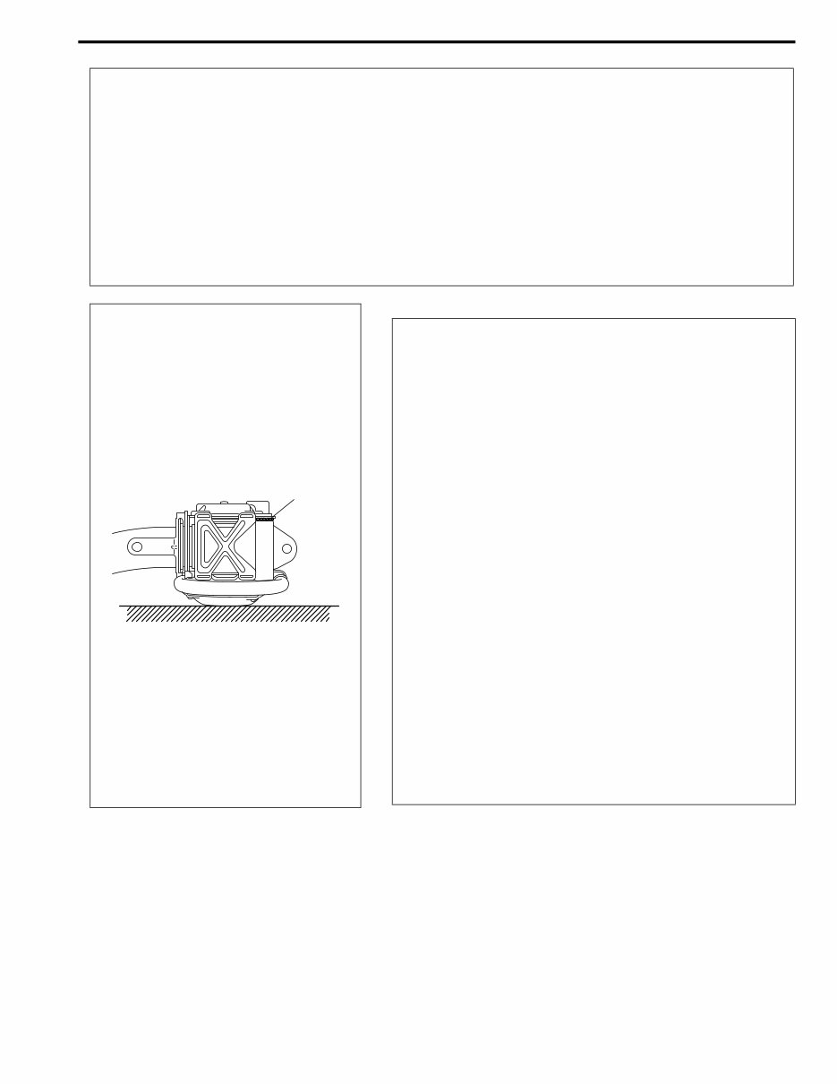
GENERAL INFORMATION 0A-5 • Even when the accident was light enough not to cause air bags to activate, be sure to inspect sys- tem parts and other related parts according to instructions under “REPAIRS AND INSPECTIONS REQUIRED AFTER AN ACCIDENT” in Section 10B. • When servicing parts other than air bag system, if shocks may be applied to air bag system compo- nent parts, remove those parts beforehand. • When handling the air bag (inflator) modules (driver, passenger and side), seat belt pretensioners (driver and passenger), side sensors or SDM, be careful not to drop it or apply an impact to it. If an excessive impact was applied, never attempt disassembly or repair but replace it with a new one. • When grease, cleaning agent, oil, water, etc. has got onto air bag (inflator) modules (driver, passen- ger and side) or seat belt pretensioners (drive and passenger), wipe off immediately with a dry cloth. WARNING: SDM • For handling and storage of a SDM, select a place where the ambient temperature below 65°C (150°F), without high humidity and away from electric noise. • During service procedures, be very careful when handling a Sensing and Diagnostic Module (SDM). Never strike or jar the SDM. • Never power up the air bag system when the SDM is not rigidly attached to the vehicle. All SDM and mounting bracket fasteners must be carefully torqued and the arrow must be pointing toward the front of the vehicle to ensure proper operation of the air bag system. The SDM could be activated when powered while not rigidly attached to the vehicle which could cause deployment and result in personal injury. WARNING: Driver and Passenger Seat Belt Pretensioners (If equipped) • For handling and storage of a live seat belt preten- sioner, select a place where the ambient temperature below 65°C (150°F), without high humidity and away from electric noise. • Never carry seat belt pretensioner by wire or connec- tor of pretensioner. When placing a live seat belt pre- tensioner on the workbench or some place like that, be sure not to lay it with its exhaust hole (1) provided side facing down. It is also prohibited to put something on its face with an exhaust hole or to put a seat belt pre- tensioner on top of another. Otherwise, personal injury may result. • Never dispose of live (inactivated) seat belt pretension- ers (drive and passenger). If disposal is necessary, be sure to activate them according to activation proce- dures described in Section 10B before disposal. • The seat belt pretensioner immediately after activation is very hot. Wait for at least half an hour to cool it off before proceeding the work. • With many service procedures, gloves and safety glasses should be worn to prevent any possible irrita- tion of the skin or eyes. 1
This is a comprehensive repair manual / service manual for your Suzuki Liana. It encompasses all models and engines, providing detailed information for professional mechanics and DIY enthusiasts.
The manual allows you to zoom in to view detailed parts and print out necessary pages without the risk of getting grease on them. It covers a wide range of categories, including:
Engine overhaul and rebuilding
Brakes
Sunroof
Timing belt replacement
Trouble codes
Wiring diagrams
Troubleshooting and diagnostics
Computer diagnostic trouble tree charts
Engine performance
Front end and alignment procedures and specifications
Suspension
Transmission removal and installation
Air conditioning service and capacities
Transmission in-car servicing
Computer diagnostic codes
Firing orders
Detailed specifications on every model covered
Factory maintenance schedules and charts
Serpentine belt routings with diagrams
Timing belt service procedures
Brake servicing procedures
Driving concerns
Complete torque specifications
U-joint and CV-joint service procedures
Repair procedures
Complete wiring diagrams
Hundreds of illustrations
Vacuum diagrams
And more...
Format: PDF
Language: English
Printable: Yes
Compatible: All Versions of Windows & Mac
Requirements: Adobe Reader
We offer various service manuals, workshop manuals, repair manuals, and owners manuals for different brands of cars and motorcycles. Instant access with no shipping cost or need to wait for a CD-ROM.
This repair manual covers the same information that professional technicians and mechanics have. It contains illustrations, diagrams, specifications, step-by-step instructions, pictures, procedures, and more.
All pages are printable, allowing you to take the necessary information with you into the garage or workshop. Save money by doing your own repairs with these easy-to-follow, step-by-step instructions.
Instant access means no shipping cost or waiting for a CD to arrive in the mail. You will receive this manual today via instant download upon completion of payment via our secure payment processor. We accept all major credit/debit cards and PayPal.