2004 Model Year PDF Service Manual GENERAL INFORMATION SECTION (Pub.No.G2320GE1) ENGINE SECTION 1 (Pub.No.G2320GE2) ENGINE SECTION 2 (Pub.No.G2320GE3) ENGINE SECTION 3 (Pub.No.G2320GE4) TRANSMISSION SECTION (Pub.No.G2320GE5) CHASSIS SECTION (Pub.No.G2320GE6) BODY SECTION (Pub.No.G2320GE7) WIRING SYSTEM SECTION (Pub.No.G2320GE8)
FUJI HEAVY INDUSTRIES LTD. G2320GE1 2004 LEGACY SERVICE MANUAL QUICK REFERENCE INDEX GENERAL INFORMATION SECTION This service manual has been prepared to provide SUBARU service personnel with the necessary information and data for the correct maintenance and repair of SUBARU vehicles. This manual includes the procedures for maintenance, disassembling, reas- sembling, inspection and adjustment of components and diagnostics for guid- ance of experienced mechanics. Please peruse and utilize this manual fully to ensure complete repair work for satisfying our customers by keeping their vehicle in optimum condition. When replacement of parts during repair work is needed, be sure to use SUBARU genuine parts. All information, illustration and specifi- cations contained in this manual are based on the latest product information available at the time of publication approval. FOREWORD FW HOW TO USE THIS MANUALS HU SPECIFICATIONS SPC PRECAUTION PC NOTE NT IDENTIFICATION ID RECOMMENDED MATERIALS RM PRE-DELIVERY INSPECTION PI PERIODIC MAINTENANCE SERVICES PM
FW-2 FOREWORD Foreword 1. Foreword A: FOREWORD These manuals are used when performing mainte- nance, repair, or diagnosis of Subaru LEGACY. Applied model: BL*****, BP***** from 2004MY The manuals contain the latest information at the time of publication. Changes in specifications, methods, etc. may be made without notice.
HOW TO USE THIS MANUALS HU Page 1. How to Use This Manuals ........................................................................... 2
HU-2 HOW TO USE THIS MANUALS How to Use This Manuals 1. How to Use This Manuals A: HOW TO USE THIS MANUALS 1. STRUCTURE Each section consists of SCT that are broken down into SC that are divided into sections for each com- ponent. The specification, maintenance and other information for the components are included, and the diagnostic information has also been added where necessary. 2. CONTENTS The first page has an index with tabs.
HU-3 HOW TO USE THIS MANUALS How to Use This Manuals 3. COMPONENT Illustrations are provided for each component. The information necessary for repair work (tightening torque, grease up points, etc.) is described on these illustrations. Information is described using symbol. To order parts, refer to parts catalogue. Example: HU-00017 (14) (9) (8) (7) (6) (10) (4) (10) (22) (11) (19) (17) (15) (13) (12) (18) (16) (1) (2) (3) (4) (5) (6) (7) (8) (11) (10) (9) (12) (13) (19) (18) (20) (17) (16) (24) (10) (25) (5) (4) (4) (4) (3) (3) (3) (2) (1) (21) (15) (23) T7 T2 T2 T2 T2 T2 T2 T4 T5 T5 T8 T6 T6 T6 T11 T10 T1 T1 T3 T3 T3 T1 T9 T4 T5 T5 T3 T4 T3 T2 T4 T2 T1 T3 (20) (21) (23) (22) (10) (24) (25) (26) (35) (34) (27) (14) (28) (29) (31) (32) (37) (30) (33) (36) T3 T2 T1 :Selective part :Replacement part :Should be lubricated with grease. :Should be lubricated with oil. :Sealing point :Tightening torque .... ,
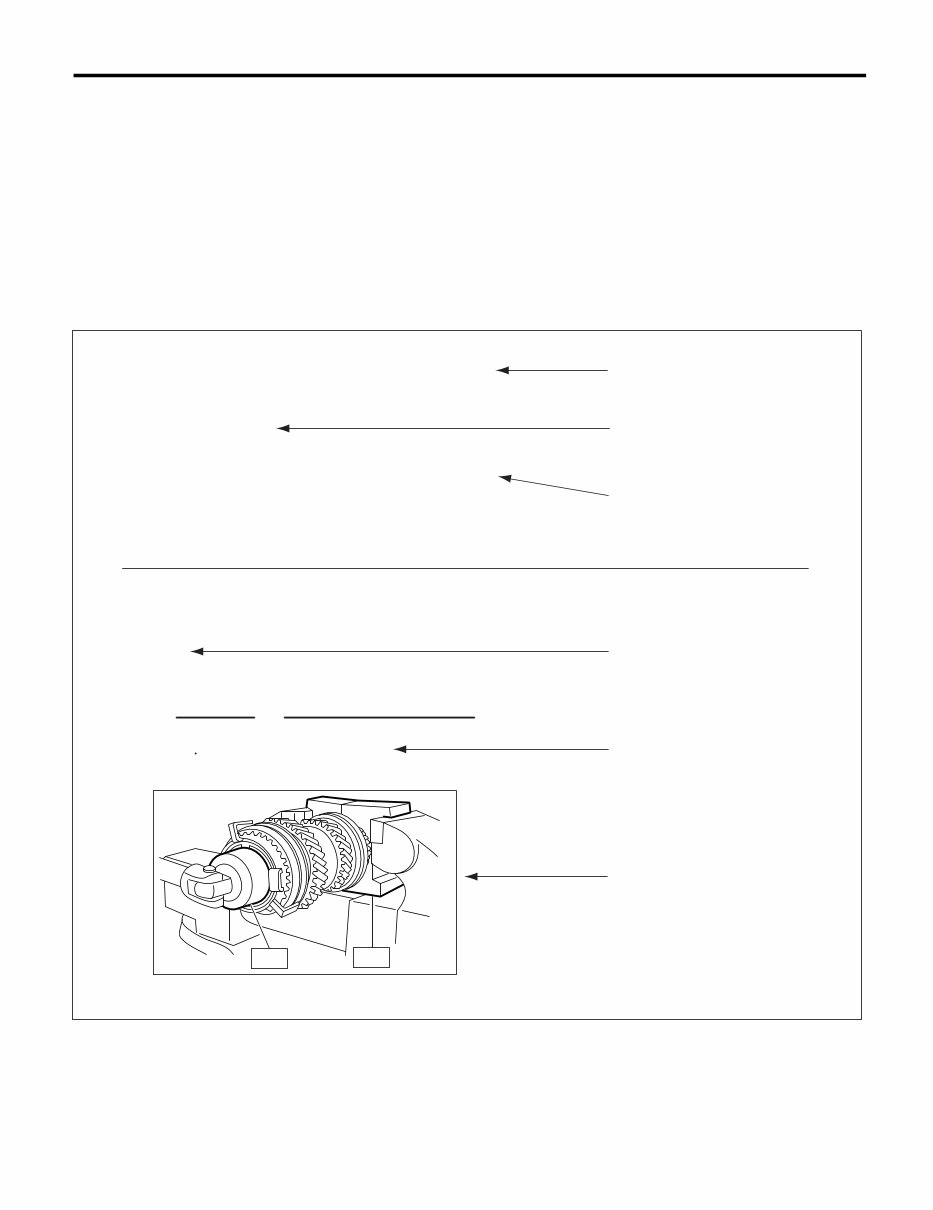
HU-4 HOW TO USE THIS MANUALS How to Use This Manuals 4. SPECIFICATION If necessary, specifications are also included. 5. INSPECTION Inspections to be carried out before and after maintenance are included. 6. MAINTENANCE • Maintenance instructions for serviceable parts describe work area and detailed step with illustration. It also describes the use of special tool, tightening torque, caution for each procedure. • If many serviceable parts are included in one service procedure, appropriate reference is provided for each parts. Example: (A) Component (D) Cautions (G) Tightening torque (B) Process (E) Tool number of special tool (H) Illustration (C) Reference (F) Name of special tool HU-00020 1) Remove the manual transmission assembly from vehicie. <Ref. to MT-33, REMOVAL, Manual Transmission Assembly.> 15.Main Shaft Assembly for Sin- gle-Range A: REMOVAL 11) Tighten the lock nuts to the specified torque us- ing ST1 and ST2. NOTE: Secure the lock nuts in two Places affer tightening. ST2 499987003 SOCKET WRENCH ST1 498937000 TRANSMISSION HOLDER (A) (B) (C) (D) (G) (E) (F) (H) Tightening torque: 118 N m (12.0 kgf-m, 86.8 ft-lb) ST1 ST2
This is a complete factory service repair manual for the 2004 Subaru Legacy. The manual contains easy-to-read text sections with high-quality diagrams and instructions, making it useful for both do-it-yourself enthusiasts and experienced mechanics. It provides step-by-step instructions and highly detailed exploded pictures and diagrams to guide you through the required job efficiently.
The 2004 Subaru Legacy Service Repair Workshop Manual covers a wide range of details on your machine, including but not limited to:
Routine Maintenance
Tune-up Procedures
Specifications
Engine Removal / Installation
Cylinder Head / Valve Train
Engine Block
Engine Lubrication
Intake Manifold / Exhaust System
Cooling and Heating
Fuel and Emissions
Transaxle
Clutch
Manual Transmission
Automatic Transmission
Differential
Driveshaft
Steering
Suspension
Brakes (including ABS)
Body
Heater and Air Conditioning
Automatic Climate Control
Electrical (including SRS)
Supplemental Restraint System (SRS)
Engine Repair
Air Conditioning
Exhaust
Emissions Control
Ignition
Steering
Wiring Diagrams
Valve Timing Procedures
Chain & Gear Replacement
General Removal & Installation Instructions
Safety Precautions
Special Tools
Tensioner Adjustments
Tightening Torques
Timing Marks
Valve Timing Instructions
Tensioner Release & Reset Methods
Chain Routing & Sprocket/Gear Valve Timing Marks
And More......
File Format: PDF
Compatible: All Versions of Windows & Mac
Language: English
Requirements: Adobe Reader & Win
No waiting, all pages are printable. The 2004 Subaru Legacy Service Repair Workshop Manual can save you money on postage and packaging. It is a valuable resource to have.











 Lifetime Access




