2003-2004 Subaru Impreza WRX STI With 5-6 Speed Manual & Automatic Transmission Service & Repair Manual
What's Included?
Lifetime Access
Fast Download Speeds
Offline Viewing
Access Contents & Bookmarks
Full Search Facility
Print one or all pages of your manual
AIRBAG SYSTEM
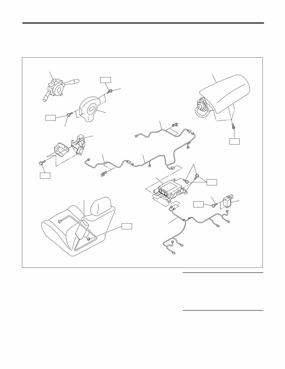
AB-2 AIRBAG SYSTEM General Description 1. General Description A: COMPONENT 1. SRS AIRBAG (1) Combination switch ASSY with roll connector (6) Hexagon head bolt (exclusive use) Tightening torque: N⋅m (kgf-m, ft-lb) (7) Side airbag sensor T1: 5.9 (0.60, 4.4) (2) TORX ® bolt T30 (8) Side airbag harness T2: 7.5 (0.76, 5.5) (3) Airbag module ASSY (Driver’s side) (9) Side airbag module T3: 10 (1.0, 7.4) (10) Airbag main harness T4: 20 (2.0, 14.8) (4) Airbag module ASSY (Passen- ger’s side) (11) Front sub sensor harness T5: 25 (2.5, 18.4) (12) Front sub sensor (5) Airbag control module (13) TORX ® bolt T30 AB-00894 T3 T2 T5 T3 T3 T4 (2) (4) (11) (3) (1) (2) (11) (12) (9) (10) (13) (8) (7) (6) (5) T1
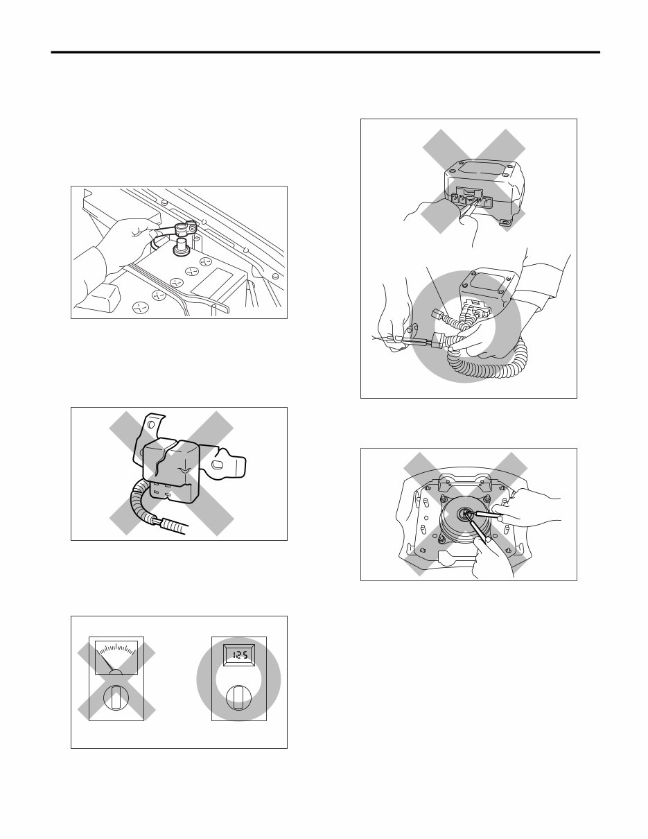
AB-3 AIRBAG SYSTEM General Description B: CAUTION • When servicing a vehicle, be sure to turn the ig- nition switch to OFF, disconnect the ground cable from battery, and wait for more than 20 seconds before starting work. • The airbag system is fitted with a backup power source. If the airbag system is serviced within 20 seconds after the ground cable is disconnected, it may inflate. • If the airbag warning light illuminates, repair the vehicle immediately. Airbag or pretensioner may in- flate incorrectly, or not inflate in collision. • If sensors, airbag module, airbag control module, pretensioner, and harness are deformed or dam- aged, replace them with new genuine parts. • When checking the airbag system, be sure to use a digital circuit tester. Infinitesimal electric current in an analog circuit tester may cause the airbag to activate erroneous- ly. • When checking, use a test harness (1). Do not directly apply the tester probe to any connector ter- minal of the airbag. Damage to the connector termi- nal may cause the airbag to activate erroneously. • Do not check continuity of either of the airbag modules for driver, passenger or side, or preten- sioner. FU-00009 AB-00120 AB-00121 AB-00122 (1) AB-00006
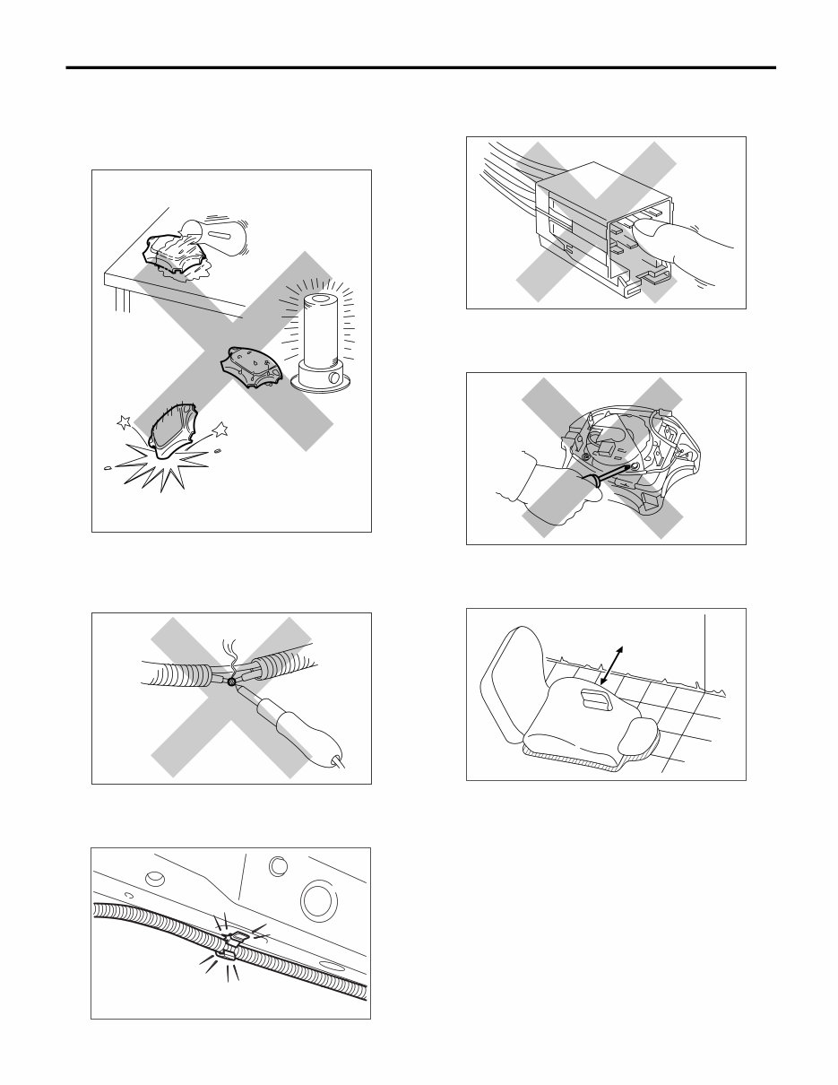
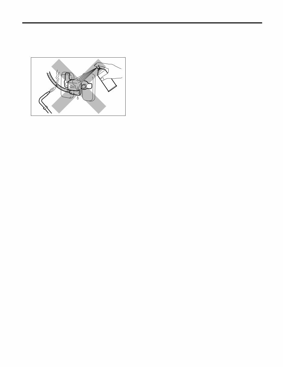
AB-4 AIRBAG SYSTEM General Description • Do not drop the airbag modulator parts, subject them to high temperature over 93°C (199°F), or let water, oil, or grease get on them; otherwise, the in- ternal parts may be damaged and reliability greatly lowered. • If any damage, opening, or rust is found on the airbag system wire harness, do not attempt to re- pair using soldering equipment. Be sure to replace the faulty harness with a new genuine part. • Install the wire harness securely with the speci- fied clips to avoid interference or tangled up with other parts. • Do not allow water or oil to come in contact with the connector terminals. Do not touch the connec- tor terminals. • Either of the airbag modules for driver, passen- ger or side, or pretensioner must not be disassem- bled. • The removed front seat with the airbag module must be kept at least 200 mm (8 in) away from walls and other objects. • Do not use the airbag or pretensioner parts from other vehicles. Always replace defective parts with new parts. • Never reuse a deployed airbag or pretensioner. • When painting or performing sheet metal work on the front part of the vehicle, including the front wheel apron, front fender, and front side frame, re- move the front sub sensors and wire harness of the airbag system. AB-00123 AB-00124 AB-00125 (1) More than 200 mm (8 in) AB-00126 AB-00127 AB-00128 (1)
AB-5 AIRBAG SYSTEM General Description • When painting or performing sheet metal work on the side of the vehicle, including the side sill, center pillar, and front and rear doors, remove the side airbag sensors and wire harness of the airbag system. AB-00129
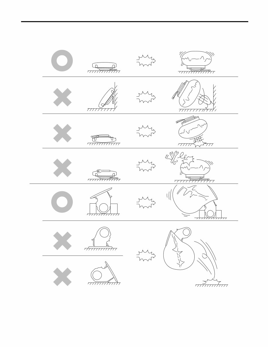
AB-6 AIRBAG SYSTEM General Description • When storing a removed airbag module, do not place any objects on it or pile airbag modules on top of each other. If the airbag inflates for some reason when it is placed with its pad side facing downward or under any object, a serious accident may result. (1) Driver’s airbag module (2) Passenger’s airbag module AB-00130 (2) (1)
AB-7 AIRBAG SYSTEM General Description C: PREPARATION TOOL 1. GENERAL TOOL TOOL NAME REMARKS TORX ® T30 Used for removal/installation of driver’s airbag module.
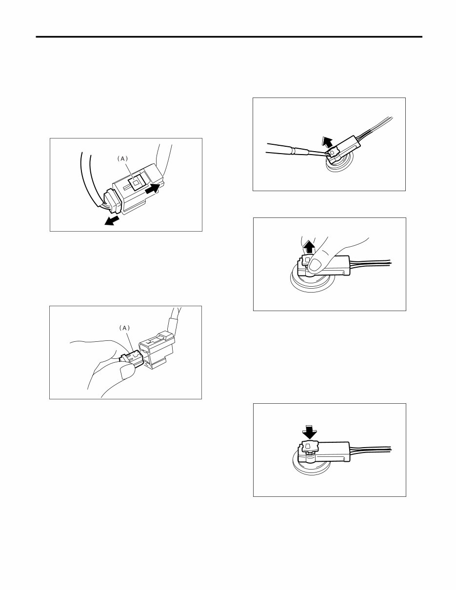
AB-8 AIRBAG SYSTEM Airbag Connector 2. Airbag Connector A: PROCEDURE 1. POWER SUPPLY 1) How to disconnect: (1) Move the slide lock (A) in the direction of the arrow. (2) Disconnect the connector with slide lock (A) moved. CAUTION: When pulling the slide lock or disconnecting the connector, be sure to hold onto the connec- tor and not the wire. 2) How to connect: Holding the connector (A), and push it in carefully until a connecting sound is heard. CAUTION: Be sure to insert the connector in until it locks. Then pull on it gently to make sure that it is locked. 2. DRIVER’S AIRBAG MODULE AND PRE- TENSIONER 1) How to disconnect: (1) Using a flat tip screwdriver, pry the push lock upward to unlock. (2) Pull the connector to disconnect from driv- er’s side airbag module assembly. 2) How to connect: Connect the connector in reverse order of discon- necting. At this time, be sure to insert the push lock in until connecting sound is heard. CAUTION: • Be sure to insert the connector in until it locks. Then pull on it gently to make sure that it is locked. • At this time, be sure to insert the push lock in. AB-00015 AB-00016 AB-00478 AB-00479 AB-00480
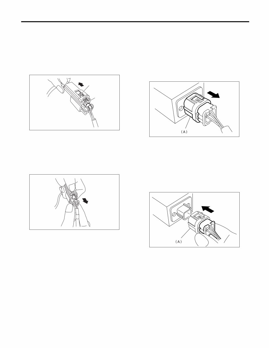
AB-9 AIRBAG SYSTEM Airbag Connector 3. DRIVER’S AIRBAG (BETWEEN AIRBAG MAIN HARNESS AND ROLL CONNECTOR), PASSENGER’S AIRBAG AND SIDE AIR- BAG 1) How to disconnect: (1) Push the lock arm (A). (2) With the lock arm (A) pushed in, move the slide lock (B) in the direction of arrow. (3) With the slide lock moved, release the lock arm (back to its original position), and discon- nect the connector. CAUTION: When pulling the side lock or disconnecting the connector, be sure to hold onto the connector and not the wire. 4. FRONT SUB-SENSOR AND SIDE AIR- BAG SENSOR 1) How to disconnect: Holding outer part (A), pull it in the direction of the arrow. CAUTION: When pulling the slide lock or disconnecting the connector, be sure to hold onto the connec- tor and not the wire. 2) How to connect: Holding the connector, and push it in carefully until a connecting sound is heard. CAUTION: • Outer (A) moves back, and so do not put your hand on the outer part. • Be sure to insert the connector in until it locks. Then pull on it gently to make sure that it is locked. AB-00017 (A) (B) AB-00018 AB-00024 AB-00025
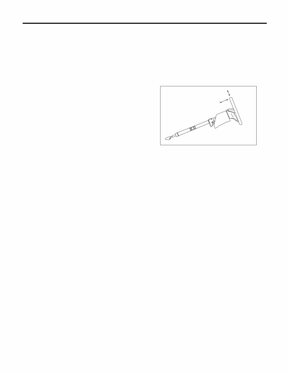
AB-10 AIRBAG SYSTEM Inspection Locations After a Collision 3. Inspection Locations After a Collision A: REPLACEMENT When airbag system is deployed, replace the fol- lowing parts. 1. FRONT COLLISION 1) Driver’s airbag module 2) Passenger’s airbag module 3) Driver’s seat belt (pretensioner) 4) Passenger’s seat belt (pretensioner) 5) Airbag control module 6) Front sub-sensor 7) Roll connector 2. SIDE COLLISION 1) Airbag control module 2) Side airbag module (operating side seat back- rest) 3) Side airbag sensor (operating side) 3. INSPECTION OF OTHER PARTS Check for the following parts, replace the damaged parts with new ones. 1) Steering wheel and steering shaft Check the steering wheel and steering shaft for mounting condition and deflection of axial and rad- ical, upward and downward direction. Check the steering shaft for deflection of axial and radical di- rection with tilt lever released. (After a collision, ab- sorbing part of steering shaft may inflate.) 2) Check the direct type connector of driver’s air- bag module, pretensioner, etc. for damage, and also check each harness for pinch and connector damage. If damage is found, replace the harness as a unit. B: INSPECTION If the vehicle is involved in a collision, even if it is a slight collision, be sure to check the following sys- tem parts. 1. DRIVER’S AIRBAG MODULE 1) Check for the following, and replace damaged parts with new parts. • Airbag module is cracked or deformed. • Harness and/or connector is cracked, deformed or open. Lead wire is exposed. • The module surface is fouled with grease, oil, water or cleaning solvent. 2) When installing a new driver’s airbag module, check the following, and replace the damaged parts with new ones. • The steering wheel is in the way, making it diffi- cult to install the airbag module. • The clearance between the driver’s airbag mod- ule and steering wheel is not constant. • The steering wheel deformation in axial and radi- al directions exceed limits. Specifications: Height deflection A Less than 6 mm (0.24 in) O.D. deflection L Less than 17 mm (0.67 in) 2. PASSENGER’S AIRBAG MODULE Check for the following, and replace damaged parts with new parts. • Airbag module is cracked or deformed. • Harness and/or connector is cracked, deformed or open. Lead wire is exposed. • Mounting bracket is cracked or deformed. 3. SIDE AIRBAG MODULE Check for the following, and replace damaged parts with new parts. • Front seat, airbag module and mounting bracket are damaged or deformed. • Harness and/or connector is cracked, deformed or open. Lead wire is exposed. 4. AIRBAG CONTROL MODULE Check for the following, and replace damaged parts with new parts. • Control module is cracked or deformed. • Mounting bracket is cracked or deformed. • Connector is scratched, cracked or deformed. • Airbag is deployed. • Side airbag is deployed. AB-00028 L A
The SUBARU IMPREZA WRX STI Full Service & Repair Manual is a comprehensive guide for owners of 2003-2004 models with 5-6 Speed Manual and Automatic Transmissions.
This manual is designed to provide step-by-step instructions and detailed illustrations to assist owners in performing maintenance and repairs on their SUBARU IMPREZA WRX STI vehicles.
With this manual, owners can save time and money by learning how to handle various repairs and services themselves. From basic maintenance tasks such as oil changes and tire rotations to more complex repairs like engine overhauls and transmission replacements, this manual covers it all.
Owners of the SUBARU IMPREZA WRX STI 2003-2004 will find this manual to be an invaluable resource for keeping their vehicles in optimal condition.
The manual includes:
Comprehensive information on engine systems, fuel systems, cooling systems, and exhaust systems.
Detailed instructions on performing electrical system repairs and troubleshooting.
Guidance on brake system repairs and maintenance.
Instructions for repairing and maintaining the suspension and steering systems.
Step-by-step procedures for repairing and servicing the transmission, including both manual and automatic options.
Troubleshooting guides for common issues and solutions.
With this SUBARU IMPREZA WRX STI Full Service & Repair Manual, owners can confidently take control of their vehicle's maintenance and repairs, ensuring it remains in excellent condition for years to come.
Recently Viewed
5,521,897Happy Clients
2,594,462eManuals
1,120,453Trusted Sellers
15Years in Business
Price:
Actual Price:
2003-2004 Subaru Impreza WRX STI With 5-6 Speed Manual & Automatic Transmission Service & Repair Manual