

1997 Subaru WRX / WRX STI Service & Repair Manual
What's Included?
Fast Download Speeds
Offline Viewing
Access Contents & Bookmarks
Full Search Facility
Print one or all pages of your manual

1.8L & 2.2L 4-CYL
Article Text
1998 Subaru Impreza
ARTICLE BEGINNING
1995-98 ENGINES
Subaru - 1.8L & 2.2L 4-Cylinder
1995-97: Impreza (1.8L)
1995-98: Impreza (2.2L), Legacy (2.2L)
* PLEASE READ THIS FIRST *
NOTE: For engine repair procedures not covered in this article,
see ENGINE OVERHAUL PROCEDURES - GENERAL INFORMATION article
in the GENERAL INFORMATION section.
ENGINE IDENTIFICATION
Engine can be identified by sixth character of Vehicle
Identification Number (VIN). The VIN is stamped on a metal plate
located on right front side of firewall. Engine identification number
is stamped on a machined pad on left rear of cylinder block.
ENGINE IDENTIFICATION CODE
ÄÄÄÄÄÄÄÄÄÄÄÄÄÄÄÄÄÄÄÄÄÄÄÄÄÄÄÄÄÄÄÄÄÄÄÄÄÄÄÄÄÄÄÄÄÄÄÄÄÄÄÄÄÄÄÄÄÄÄÄ
Application VIN Code
1995
1.8L ................................................. 2
2.2L ................................................. 6
1996
1.8L
AWD ................................................ 2
FWD ................................................ 1
2.2L
AWD ................................................ 4
FWD ................................................ 3
1997
1.8L ................................................. 2
2.2L
AWD ................................................ 4
FWD ................................................ 3
1998
2.2L
AWD ................................................ 4
FWD ................................................ 3
ÄÄÄÄÄÄÄÄÄÄÄÄÄÄÄÄÄÄÄÄÄÄÄÄÄÄÄÄÄÄÄÄÄÄÄÄÄÄÄÄÄÄÄÄÄÄÄÄÄÄÄÄÄÄÄÄÄÄÄÄ
ADJUSTMENTS
VALVE CLEARANCE ADJUSTMENT
NOTE: Engines on 1995-96 models are equipped with hydraulic lash
adjusters. Valve adjustment is not required.
NOTE: Perform valve adjustment when engine is cold.
1997-98 Models
Disconnect battery ground cable. Remove connector from mass
airflow sensor. Remove air intake duct and upper air cleaner cover as
a unit. Remove air filter. Disconnect washer fluid pump wire connector
and hose. Remove washer fluid tank. Remove right side timing belt
cover. Remove spark plug wires.
2) Raise and support vehicle. Remove undercovers. Disconnect
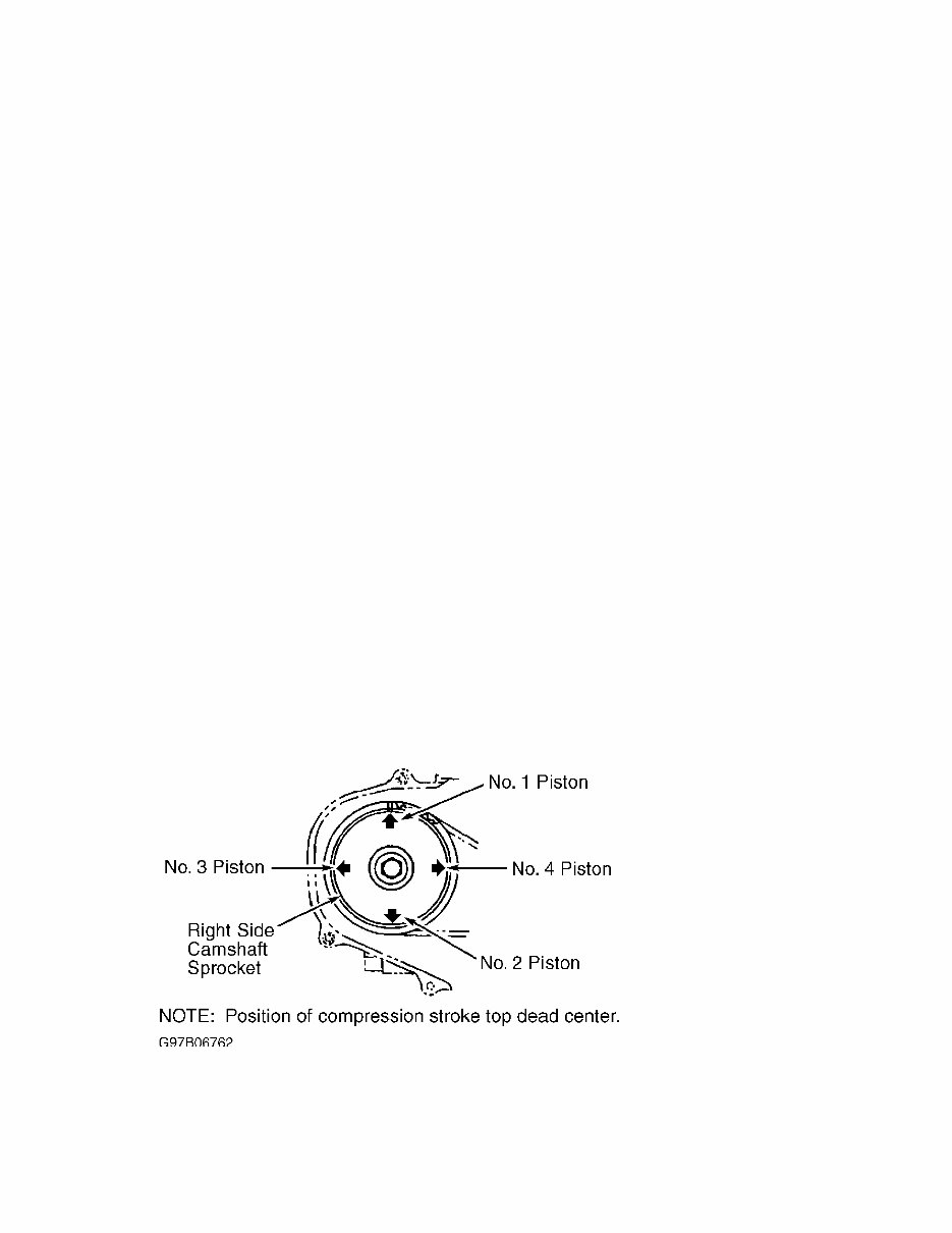
PCV hoses and remove valve covers. Set No. 1 cylinder to TDC of
compression stroke. Arrow mark on right-side camshaft sprocket should
be pointing up. See Fig. 1. Using feeler gauge, measure No. 1 cylinder
valve clearance. Adjust as needed. Tighten lock nut to 78-95 INCH lbs.
(9-11 N.m). See VALVE CLEARANCE SPECIFICATION.
3) Rotate crankshaft 180 degrees clockwise (camshaft turns 90
degrees) so the next cylinder in firing order is at TDC, and
check/adjust valve clearance for that cylinder. See Fig. 1. Repeat
procedure until all valves have been adjusted.
Fig. 1: Identifying Camshaft/Cylinder Top Dead Center Positions
Courtesy of Subaru of America, Inc.
VALVE CLEARANCE SPECIFICATION
ÄÄÄÄÄÄÄÄÄÄÄÄÄÄÄÄÄÄÄÄÄÄÄÄÄÄÄÄÄÄÄÄÄÄÄÄÄÄÄÄÄÄÄÄÄÄÄÄÄÄÄÄÄÄÄÄÄÄÄÄ
Application Clearance In. (mm)

Intake ............................. .0070-.0087 (.18-.22)
Exhaust ............................ .0091-.0106 (.23-.27)
ÄÄÄÄÄÄÄÄÄÄÄÄÄÄÄÄÄÄÄÄÄÄÄÄÄÄÄÄÄÄÄÄÄÄÄÄÄÄÄÄÄÄÄÄÄÄÄÄÄÄÄÄÄÄÄÄÄÄÄÄ
REMOVAL & INSTALLATION
* PLEASE READ THIS FIRST *
NOTE: For reassembly reference, label all electrical connectors,
vacuum hoses and fuel lines before removal. Also place mating
marks on engine hood and other major assemblies before
removal.
FUEL PRESSURE RELEASE
1995-97 Models
Disconnect fuel pump wiring connector located under rear
seat. Start engine and let idle until it stalls. Crank engine for an
additional 5 seconds. Turn ignition off.
1998 Models
Disconnect fuel pump relay connector located under left side
of dash. Start engine and run until it stalls. Crank engine for an
additional 5 seconds. Turn ignition off.
ENGINE
NOTE: Transaxle remains in vehicle with engine removal.
Removal
1) Release fuel pressure. See FUEL PRESSURE RELEASE. Drain
cooling system. Disconnect battery and remove from vehicle. Remove air
intake duct/upper air cleaner cover assembly. Disconnect radiator and
heater hoses. Disconnect A/T cooler lines (if equipped). Remove
radiator.
2) Identify, mark and disconnect electrical connectors,
vacuum hoses and fuel lines that interfere with engine removal.
Discharge A/C system using approved refrigerant recovery/recycling
equipment. Disconnect accelerator cable, cruise control cable (if
equipped) and clutch cable/hill holder cable at clutch release fork
(M/T).
3) Remove accessory drive belts. Remove power steering pump
with hoses attached and set aside. Remove hoses from A/C compressor
and set aside. Raise and support vehicle. Remove front exhaust pipe.
Disconnect engine mount from front crossmember. Remove nuts attaching
lower engine to transaxle.
4) Remove all brackets interfering with engine removal.

Remove flywheel access cover. Disconnect bolts securing drive plate to
torque converter (A/T). Support engine using hoist. Support transaxle
using floor jack. Remove bolts attaching upper side of engine to
transmission. Remove engine.
Installation
To install, reverse removal procedure. Tighten bolts and nuts
to specification. See TORQUE SPECIFICATIONS. Adjust all control
cables. Check all fluid levels.
INTAKE MANIFOLD
Removal & Installation
1) Release fuel pressure. See FUEL PRESSURE RELEASE. Remove
"V" belt. Disconnect negative battery cable. Remove air intake
duct/upper air cleaner cover assembly. Disconnect throttle cable.
Disconnect cruise control cable (if equipped). Remove power steering
belt. Remove power steering pump with hoses attached and set aside.
2) Disconnect PCV and ventilation hoses. Disconnect spark
plug wires. Disconnect coolant hoses and air by-pass hose from
throttle body. Disconnect electrical connectors and vacuum hoses
interfering with intake manifold removal.
3) Remove EGR pipe. Disconnect fuel hoses from pipes. Remove
intake manifold-to-cylinder head bolts. Remove intake manifold. To
install, reverse removal procedure. Use NEW gaskets. Tighten bolts to
specification. See TORQUE SPECIFICATIONS.
EXHAUST MANIFOLD
NOTE: Exhaust manifold is integral with cylinder head.
CYLINDER HEAD
Removal
Release fuel pressure. See FUEL PRESSURE RELEASE. Drain
engine coolant. Remove timing belt and camshaft sprocket. See TIMING
BELT. Remove intake manifold and exhaust pipe. See INTAKE MANIFOLD.
Remove cylinder head bolts in reverse order of tightening sequence.
See Fig. 2. Remove cylinder head and gasket.
Inspection
Check cylinder head warpage and height. Resurface head if
warpage exceeds specification. See CYLINDER HEAD table under
ENGINE SPECIFICATIONS. Replace cylinder head if height is not within
specification.
Installation
Ensure mating surfaces are clean and dry. Install head

gasket. Coat head bolt threads with oil. Tighten bolts to
specification in sequence. See Fig. 2. See TORQUE SPECIFICATIONS. To
complete installation, reverse removal procedure.
Fig. 2: Cylinder Head Bolt Tightening Sequence
Courtesy of Subaru of America, Inc.
TIMING BELT
Removal
1) Remove generator drive belt. Remove A/C belt and
tensioner, if equipped. Remove crankshaft pulley. If engine is removed
from vehicle, crankshaft can be held using Crankshaft Pulley Wrench
(499977000).
Fig. 3: Identifying Crankshaft Pulley & Timing Belt Covers
Courtesy of Subaru of America, Inc.
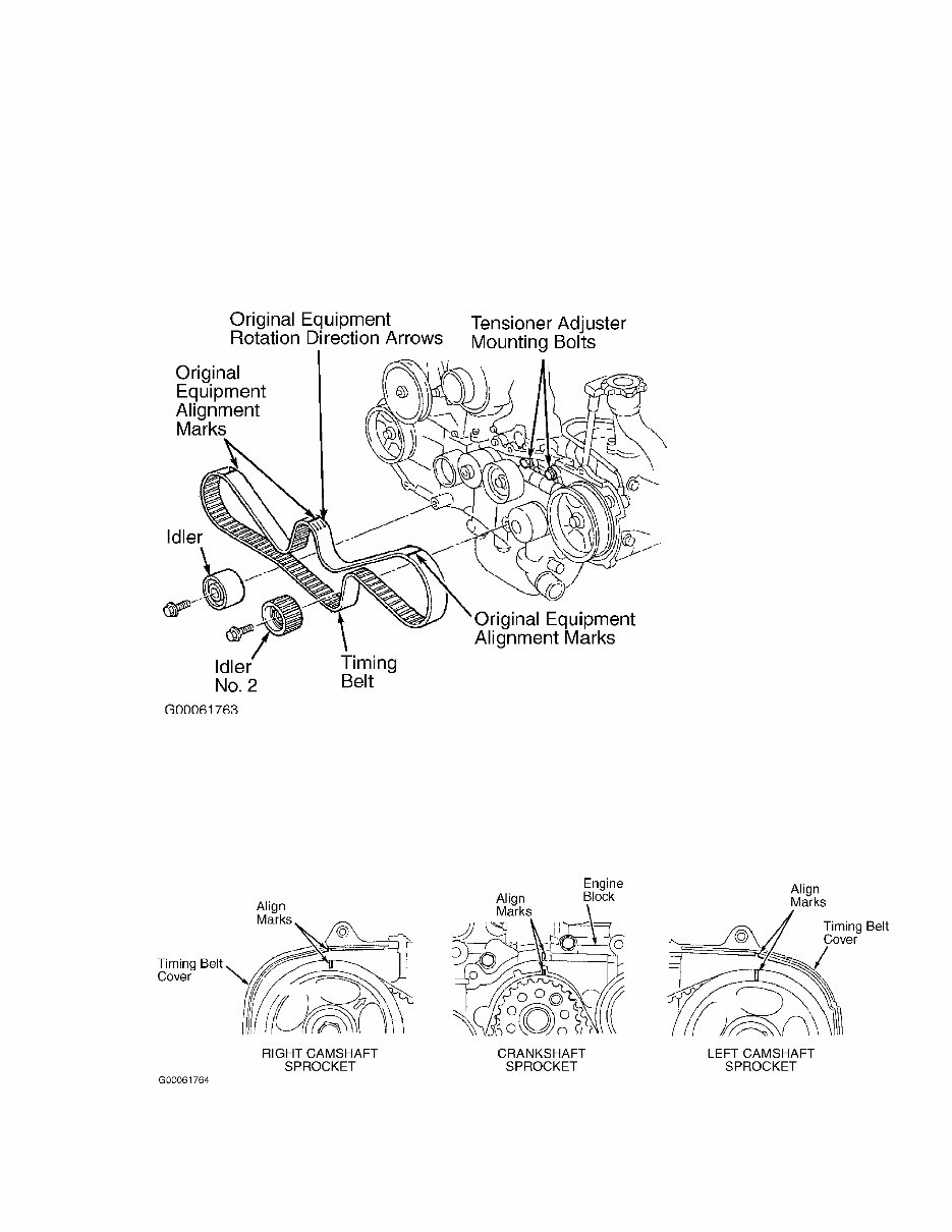
2) Remove left, right and front timing belt covers. See
Fig. 3. If timing belt is to be reused, mark belt to indicate original
direction of rotation before removal, if original marks are worn away
or faded. Also mark belt to indicate belt-to-sprocket alignment, if
original marks are worn away or faded. See Fig. 4.
Fig. 4: Identifying Timing Belt Components
Courtesy of Subaru of America, Inc.
3) To mark belt, turn crankshaft with Crankshaft Socket
(499987500) to align marks on crankshaft sprocket and left and right
camshaft sprockets with notches on timing belt cover and engine block.
See Fig. 5.
Fig. 5: Aligning Crankshaft Sprocket & Left & Right Camshaft
Sprocket Marks
Courtesy of Subaru of America, Inc.
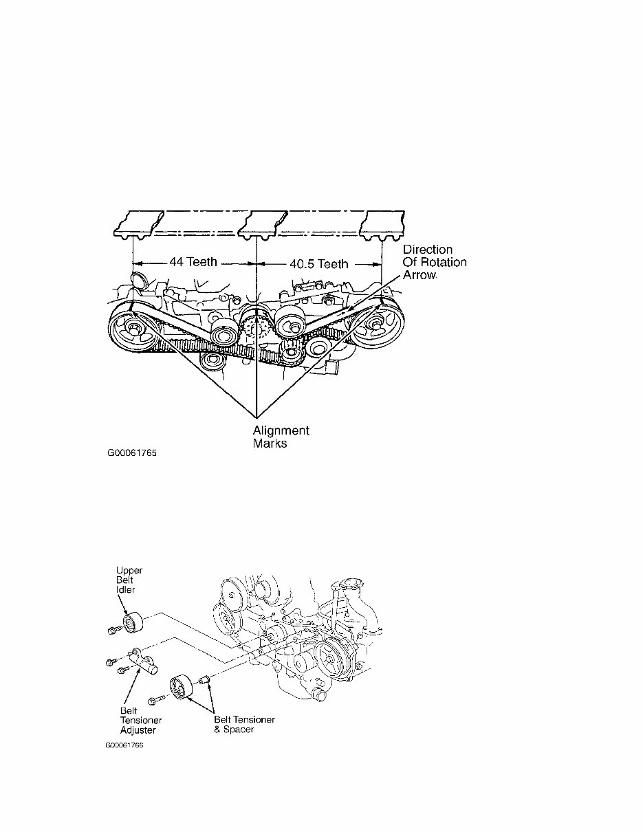
4) Use White paint to mark direction of rotation and to mark
timing belt in relation to sprocket timing marks. When marks are
properly aligned, 44 teeth should be on right side of crankshaft
sprocket and 40.5 teeth should be on left side of crankshaft sprocket.
See Fig. 6.
Fig. 6: Aligning Timing Belt Before Removal (Impreza)
Courtesy of Subaru of America, Inc.
5) Loosen tensioner adjuster mounting bolts. Remove belt
idler, and belt idler No. 2. Remove timing belt. Remove upper belt
idler. Remove belt tensioner and spacer. Remove belt tensioner
adjuster. See Fig. 7
Fig. 7: Removing Timing Belt Tensioner Components
Courtesy of Subaru of America, Inc.
Inspection
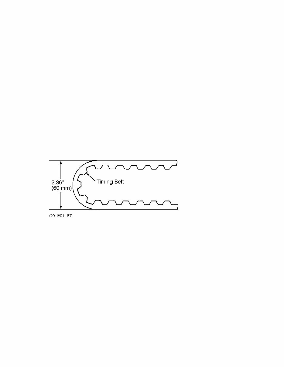
1) Inspect timing belt for wear on rounded edges of drive
teeth. Inspect belt for signs of oil contamination. Replace belt if it
is damaged or contaminated. Inspect belt tensioner adjuster oil seals
for leaks. Inspect rod ends for abnormal wear and scratches. Timing
belt bend radius must be greater than 2.36" (60.0 mm). See Fig. 8.
2) Slight trace of oil at rod oil seal does not indicate a
problem. While holding tensioner with both hands, push rod section
against floor or wall using a force of 33-110 lbs. (15-50 kg) to
ensure rod section does not move.
3) If rod section moves, replace tensioner adjuster with a
NEW one. Measure extension of rod beyond body. Rod extension should be
.606-.646" (15.40-16.40 mm). Replace belt tensioner adjuster if
extension of rod is not as specified. Inspect belt tensioner and belt
adjuster rod mating surface. Check spacer and tensioner bushing for
wear.
Fig. 8: Measuring Timing Belt Bend Radius
Courtesy of Subaru of America, Inc.
Installation
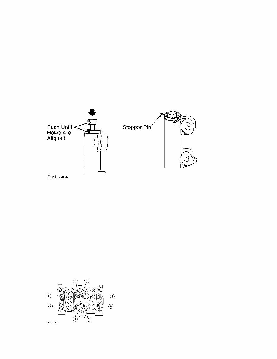
CAUTION: DO NOT allow press pressure to exceed 2205 lbs. (992 kg).
DO NOT release pressure until stopper pin is completely
installed.
1) Ensure timing marks are aligned. Using a press, push rod
into body until holes in belt tensioner adjuster rod and adjuster body
are aligned. Install .059" (1.50 mm) diameter stopper pin into holes
in adjuster body and rod. See Fig. 9.
2) Install belt tensioner adjuster, and temporarily tighten
mounting bolts while tensioner adjuster is pushed completely to the
right. Install belt tensioner and spacer. Install upper belt idler.
Ensure crankshaft and camshaft alignment marks are aligned. See Fig. 5
.
3) Install timing belt, being careful not to move sprockets.
Ensure rotation direction of belt is correct and that all alignment
marks are aligned when belt is installed. See Fig. 6. Install belt
idler No. 2 and belt idler. Loosen tensioner adjuster mounting bolts
and push tensioner adjuster completely left. Tighten tensioner
adjuster mounting bolts.
4) Ensure marks on timing belt and sprockets align. See
Fig. 6. Remove stopper pin from tensioner adjuster. Install timing
belt covers, crankshaft pulley and generator drive belt. Install A/C
belt and tensioner, if equipped. Remove rocker covers, and ensure
valve lash adjuster does not contain air.
Fig. 9: Installing Tension Adjuster Rod Stopper Pin
Courtesy of Subaru of America, Inc.
ROCKER ARM ASSEMBLY
Removal & Installation
1) Disconnect PCV hose, and remove rocker cover. Loosen, but
DO NOT remove, bolt No. 1. See Fig. 10. Remove rocker bolts No. 2-4 in
order. Remove bolts No. 5-8. Remove rocker arm assembly.
2) On models with hydraulic lash adjusters, ensure rocker arm
assembly air vent remains facing upward or submerge rocker arm
assembly in clean engine oil.
3) To install, reverse removal procedure. DO NOT allow rocker
arm assembly to gouge dowel/alignment pins. Tighten bolts in reverse
order of loosening sequence to specification. See Fig. 10. See
TORQUE SPECIFICATIONS.
Fig. 10: Rocker Bolt Loosening Sequence
Courtesy of Subaru of America, Inc.

CAMSHAFT
Removal
Remove timing belt, valve covers and camshaft sprockets. See
TIMING BELT.
NOTE: The following procedure is for removal of left camshaft.
Procedure for right camshaft is similar.
Remove rocker arm assembly. See ROCKER ARM ASSEMBLY. Remove
camshaft position sensor. Remove valve lash adjusters and submerge in
clean engine oil (if equipped). Remove oil dipstick tube mounting
bolt. Remove camshaft support and "O" ring. Remove camshaft. Remove
oil seals only if necessary.
Inspection
1) Place camshaft in "V" blocks. Measure bend. Bend limit is
.001" (.025 mm). Check cam face condition. Remove minor burrs by
grinding using oil stone. Check cam height and journal for damage or
wear.
2) Measure outside diameter of camshaft journal and inside
diameter of cylinder head journal to determine camshaft oil clearance.
If clearance is not within specification, replace camshaft or cylinder
head as necessary. See CAMSHAFT under ENGINE SPECIFICATIONS.
3) Measure camshaft end play. If end play is not within
specification, replace camshaft support.
Installation
1) Apply a coat of clean engine oil to camshaft journals.
Install camshaft. Lubricate "O" ring and Install to camshaft support.
Install camshaft support.
2) Apply grease to oil seal lips. Using Oil Seal Guide
(499597000) and Oil Seal Installer (499587100), install oil seal on
camshaft support. To complete installation, install rocker cover,
timing belt, camshaft sprockets and related parts. Perform necessary
adjustments.
OIL PAN
Removal & Installation
Drain oil. Remove oil pan bolts. Remove oil pan and gasket.
To install, reverse removal procedure using NEW gasket. Tighten bolts
to specification. See TORQUE SPECIFICATIONS.
WATER PUMP
Removal
1) Disconnect negative battery cable. Drain engine coolant.
You're Reading a Preview
What's Included?
Fast Download Speeds
Offline Viewing
Access Contents & Bookmarks
Full Search Facility
Print one or all pages of your manual
$37.99
Viewed 12 Times Today


Secure transaction
What's Included?
Fast Download Speeds
Offline Viewing
Access Contents & Bookmarks
Full Search Facility
Print one or all pages of your manual
$37.99
Get your hands on the 1997 Subaru WRX / WRX STI Service & Repair Manual. Whether you're a professional mechanic or a DIY enthusiast, this manual provides comprehensive instructions and procedures to help you fix your vehicle. It includes technical data, detailed diagrams, a complete list of car parts, and clear pictures that make the repair process accessible for everyone. Covering maintenance, engine repair, control systems, mechanical components, fuel service specifications, emission control, and more, this manual equips you with step-by-step instructions, wiring schematics, and precise specifications to confidently diagnose and repair your vehicle. Available in .PDF format, it is fully compatible with Windows and Mac.
- Complete repair manual for 1997 Subaru WRX / WRX STI
- Ideal for professional mechanics and DIY enthusiasts
- Comprehensive instructions, detailed diagrams, and technical data
- Covers maintenance, engine repair, control systems, and more
- Available in .PDF format for both Windows and Mac


