BODY REPAIR MANUAL BS Page 1. Foreword ..................................................................................................... 2 2. Panel Components...................................................................................... 6 3. Galvanized Sheet Metal ............................................................................ 16 4. Body Construction ..................................................................................... 17 5. Gauge Values for Fitting ........................................................................... 22 6. Plastic Parts and Materials........................................................................ 29 7. List of Plastic Material Notations ............................................................... 32 8. Body Sealing ............................................................................................. 33 9. Anticorrosion Wax ..................................................................................... 37 10. Undercoat.................................................................................................. 45 11. Fuel Flap ................................................................................................... 52 12. Body Reference Points ............................................................................. 53 13. Radiator Panel (total replacement) ........................................................... 70 14. Front Wheel Apron (total replacement) ..................................................... 76 15. Front Side Frame (total replacement) ....................................................... 82 16. Closing Plate (partial replacement) ........................................................... 88 17. Front Side Frame (partial replacement) .................................................... 90 18. Toe Board Lower Reinforcement (total replacement) ............................... 92 19. Front Pillar (partial replacement) ............................................................... 96 20. Center Pillar (partial replacement) .......................................................... 104 21. Rear Quarter (partial replacement) ......................................................... 110 22. Rear Quarter End (total replacement) ..................................................... 114 23. D-pillar Reinforcement (partial replacement) .......................................... 116 24. Rear Wheel Apron (partial replacement)................................................. 120 25. Side Sill Outer (partial replacement) ....................................................... 124 26. Rear Skirt (total replacement) ................................................................. 128 27. Rear Side Frame Upper Rear (total replacement) .................................. 132 28. Rear Floor Side (total replacement) ........................................................ 136 29. Rear Floor Pan (total replacement) ......................................................... 140 30. Rear Side Frame Lower Rear (total replacement) .................................. 144 31. Closing Plate (total replacement) ............................................................ 148 32. Side Sill Inner Rear (total replacement) .................................................. 152 33. Rear Frame (total replacement) .............................................................. 156 34. Roof Panel (total replacement) ............................................................... 162
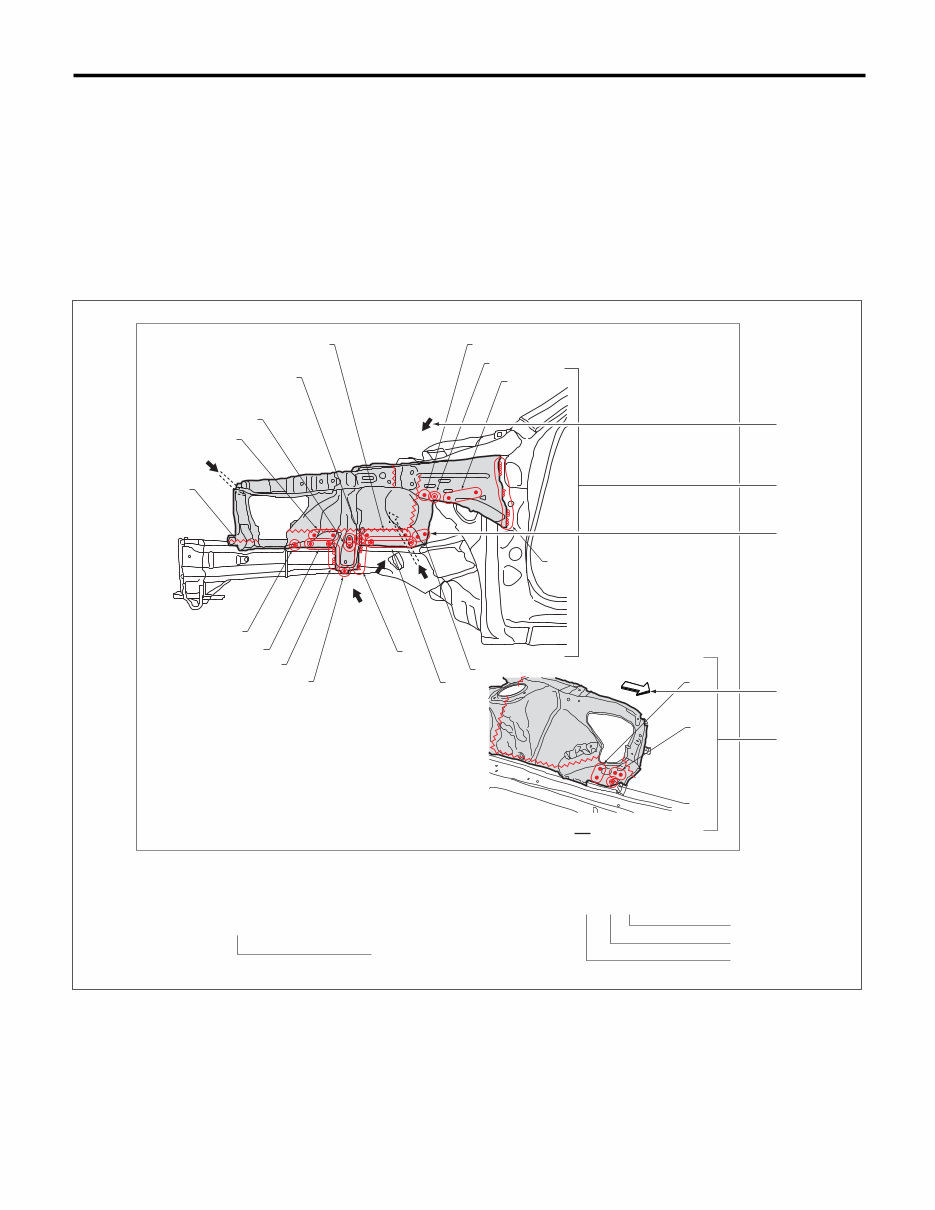
BS - 2 Foreword 1. Foreword A: USE OF THIS MANUAL This manual explains the points to be observed during removal and installation of parts separately by loca- tion. 1. ILLUSTRATION EXAMPLE • Symbols and number of points indicate the welding method and the number of welding points. Text in brackets indicates the direction for removal of welded parts, and numbers indicate the number of plates to be drilled in panels of welded parts to be removed. • An enclosure by a broken line indicates work from the opposite side (rear side). (1) Overall view (A) Welding method (2) View (B) View direction (3) Number of welding points etc. (C) Direction towards the front of the vehicle (4) Removal direction (5) Number of plates to be drilled (6) Cautions for the work etc. BS-02458 Radiator panel removal condition (1) Rough cutting (4) 1 point (outside · 2) (7) 2 points (outside · 1, belt sander) (2) 1 point (outside · 1) (5) 4 points (outside · 1) (8) 2 points (outside · 1) (3) 6 points (outside · 1) (6) 3 points (outside · 1) (9) 4 points (outside · 1, belt sander) A B D C E (1) (2) (7) (6) (2) (2) (2) (4) (5) (9) (8) (5) (7) (3) (2) (2) A (1) (1) (2) (B) (1) (A) (C) (2) (5) (4) (3) (6)
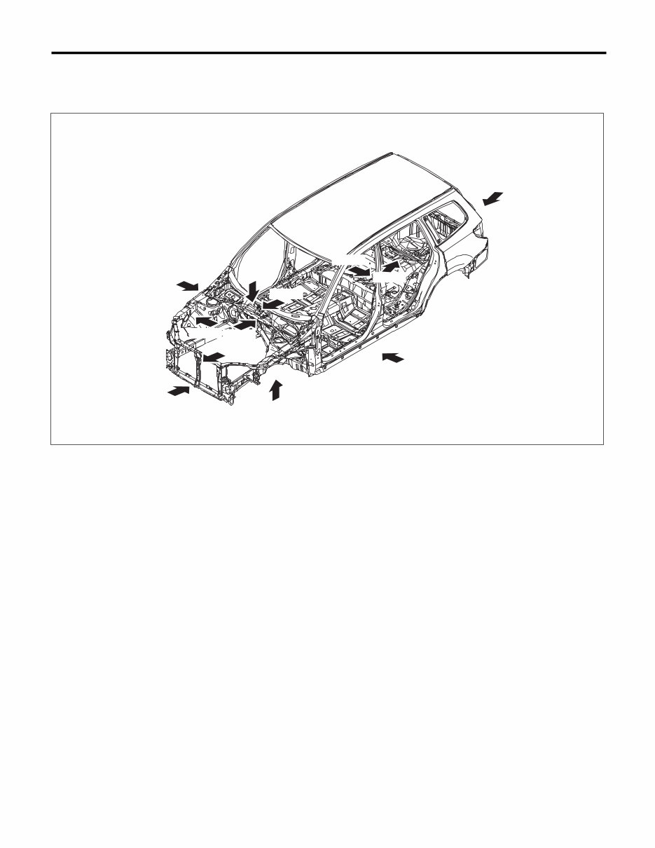
BS - 3 Foreword 2. REMOVAL DIRECTION Division is made into the four groups of inside, outside, top, and bottom, and these directions are defined as shown in the following figure. BS-03190 Top Outside Outside Bottom Outside Outside Inside Inside Inside Inside Inside Inside
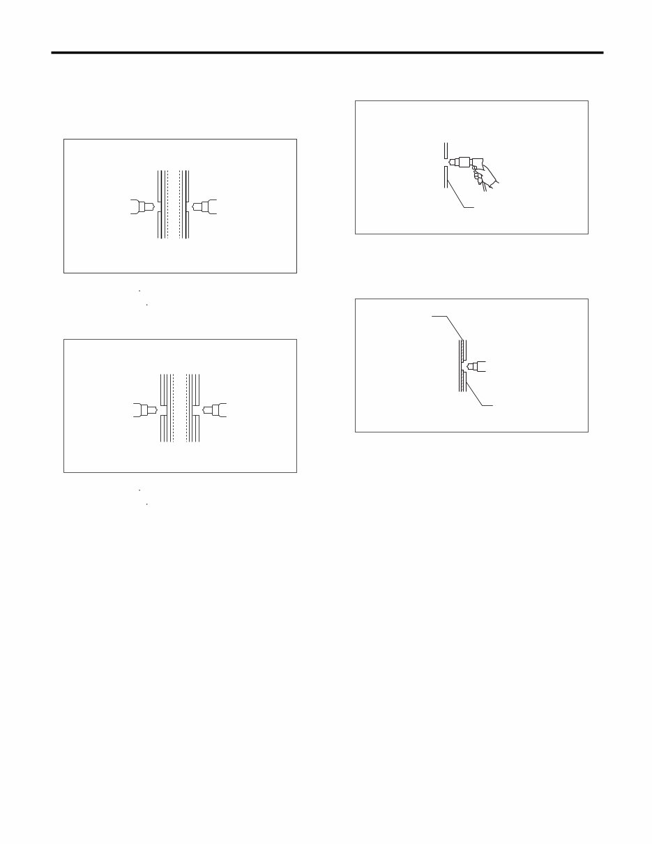
BS - 4 Foreword 3. NUMBER OF PANELS TO BE DRILLED Depending on the number of panels, drilling is done through one panel or two panels, and this number is listed together with the removal direction. (1) Drilling through one plate (2) Drilling through two plates 4. HOLE DRILLING FOR PLUG WELDING (1) Drilling of holes for plug welding in service parts (2) Drilling of holes for plug welding in service parts, matching the holes on the vehicle side (A) (Inside 1) (B) (Outside 1) (C) (Inside 2) (D) (Outside 2) (B) (A) Inside Outside BS-00651 (D) (C) Inside Outside BS-00652 (1) Service part (1) Vehicle side (2) Service part (1) (Service part) BS-00653 (1) (Service part, matching) (2) BS-00654
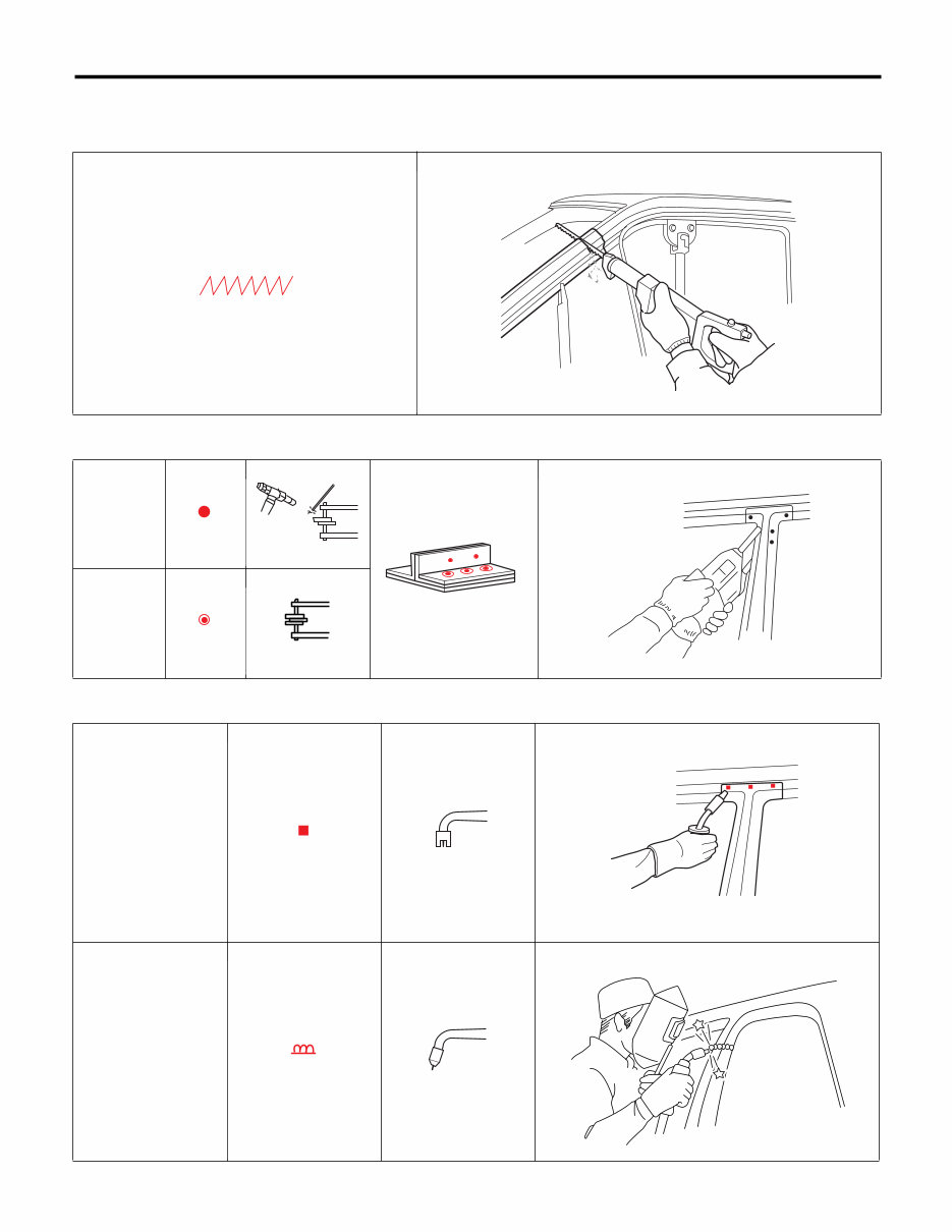
BS - 5 Foreword 5. MEANING OF SYMBOLS • Cutting • Spot welding • Carbon dioxide gas arc welding (MIG welding) Two overlap- ping parts Three or more over- lapping parts Plug welding Continuous welding BS-00352 BS-00267 BS-00655 BS-00656 BS-00657 BS-00658 BS-00659 BS-00660 BS-00661 BS-00662 BS-00663 BS-00664 BS-00665 BS-00666
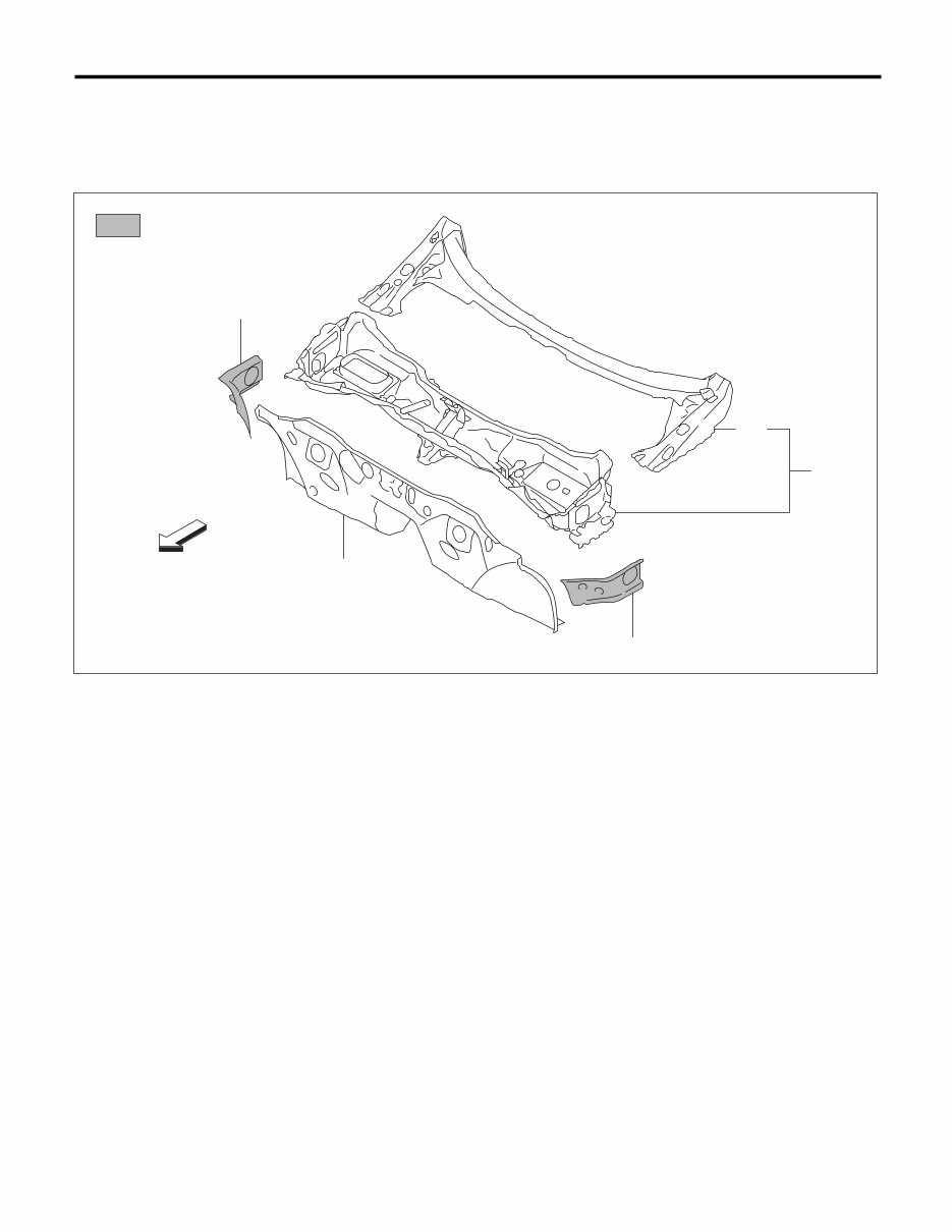
BS - 6 Panel Components 2. Panel Components A: COMPONENTS 1. TOE BOARD & FRONT PANEL (a) High-strength steel (1) Front panel and Duct (3) Toe board (4) Gusset (2) Front panel BS-03333 :(a) FRONT (4) (3) (4) (1) (2)
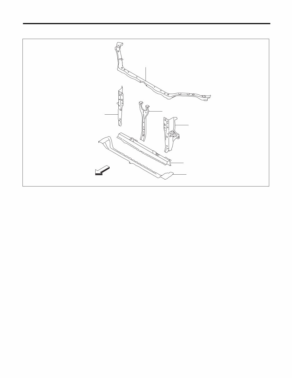
BS - 8 Panel Components 3. FRONT WHEEL APRON (a) High-strength steel (1) Front suspension bracket (5) Front wheel apron upper (9) Front wheel apron left (2) Closing plate (6) Side upper frame (10) Fender bracket left (3) Fender bracket right (7) Battery bracket (4) Front wheel apron right (8) Front tie-down BS-03115 :(a) FRONT (3) (4) (8) (2) (1) (6) (5) (7) (9) (10) (2) (1) (8) (5) (6)
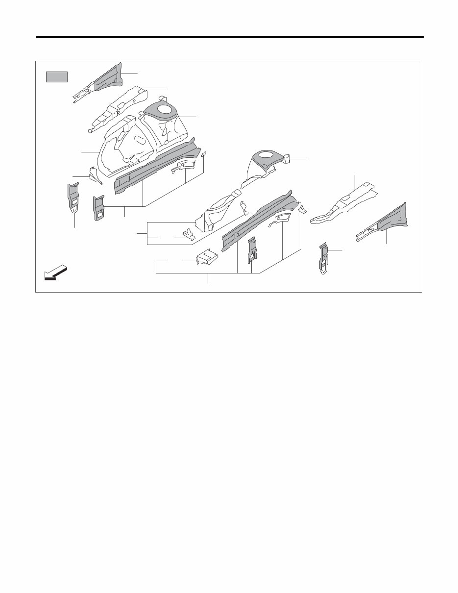
BS - 9 Panel Components 4. FRONT SIDE FRAME (a) High-strength steel (1) Front side frame front (7) Plate B (13) Toe board crossmember side (2) Bumper bracket front (8) Hook Pipe (14) Pitching stopper bracket (3) Separator (9) Front frame gusset C (15) Toe board crossmember center (4) Front frame gusset (10) Front side frame rear (16) Side frame (5) Front frame plate front (11) Toe board reinforcement (6) Plate A (12) Floor crossmember front BS-03116 FRONT :(a) (2) (3) (5) (4) (1) (7) (6) (16) (9) (8) (10) (9) (11) (4) (5) (3) (2) (1) (10) (11) (14) (13) (15) (13) (16) (12)
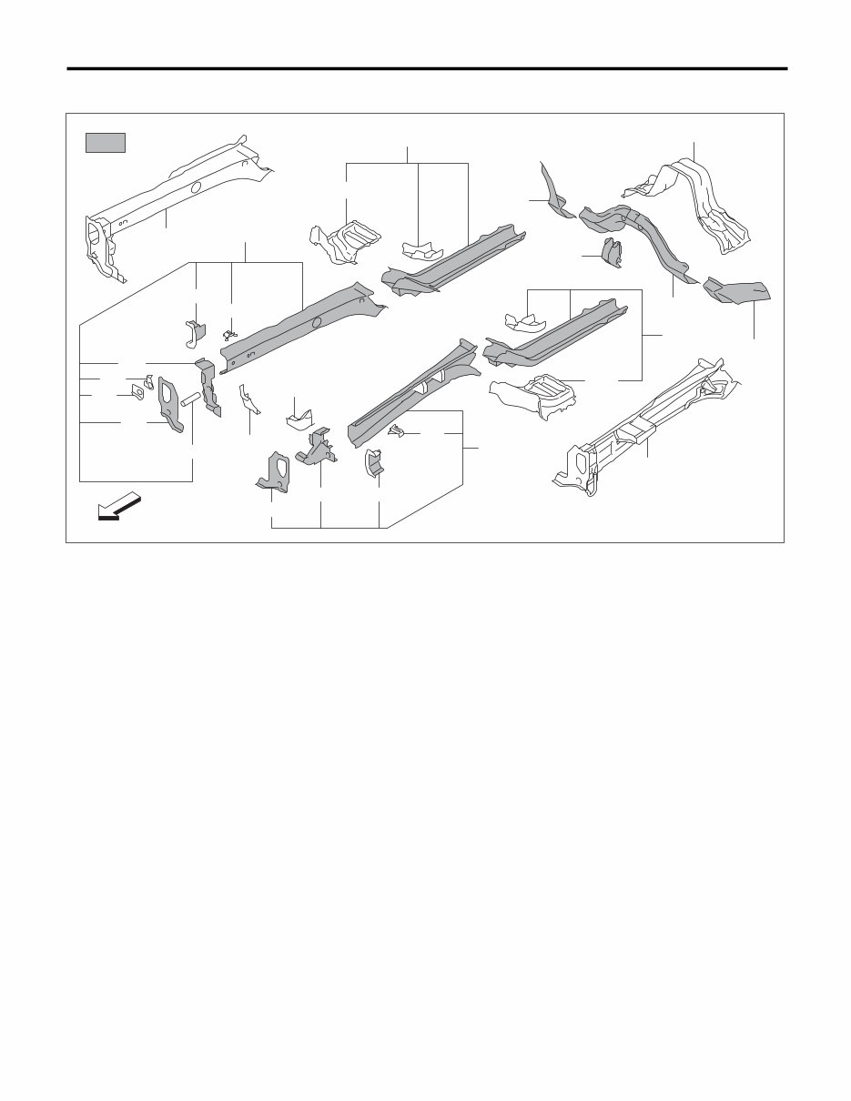
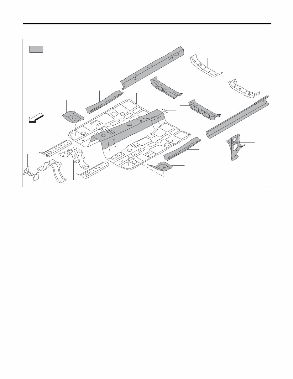
BS - 10 Panel Components 5. FRONT FLOOR PANEL (a) High-strength steel (1) Instrument panel bracket (5) Toe board reinforcement upper (9) Front pillar inner lower (2) Floor crossmember center (6) Front floor frame rear (10) Front seat crossmember rear (3) Front floor frame front (7) Front floor pan (11) Front seat crossmember front (4) Floor crossmember rear (8) Side sill inner (12) Hand brake reinforcement BS-03117 FRONT :(a) (2) (4) (3) (1) (5) (3) (6) (7) (12) (8) (11) (11) (5) (6) (10) (10) (8) (9)
This service and repair manual for the 2012 Subaru Forester (SH) provides detailed technical instructions for maintenance, diagnostics, and repair tasks. Designed to meet factory specifications, it covers essential systems with step-by-step procedures and factory-recommended maintenance schedules to ensure accurate servicing.
Key components covered include the engine, transmission, suspension, brakes, and electrical systems. The manual also features factory-authorized wiring diagrams, torque settings, and detailed parts illustrations, making it a reliable resource for routine maintenance and complex mechanical repairs on the 2012 Forester SH model.
Available in a digital format for easy access, this manual can be used on computers or mobile devices, making it practical for workshop or at-home repairs. Whether you’re a professional mechanic or a DIY enthusiast, this comprehensive service and repair manual is indispensable for keeping your Subaru Forester running reliably.
Printable: Yes Language: English Compatibility: Pretty much any electronic device, incl. PC & Mac computers, Android and Apple smartphones & tablet, etc. Requirements: Adobe Reader (free)