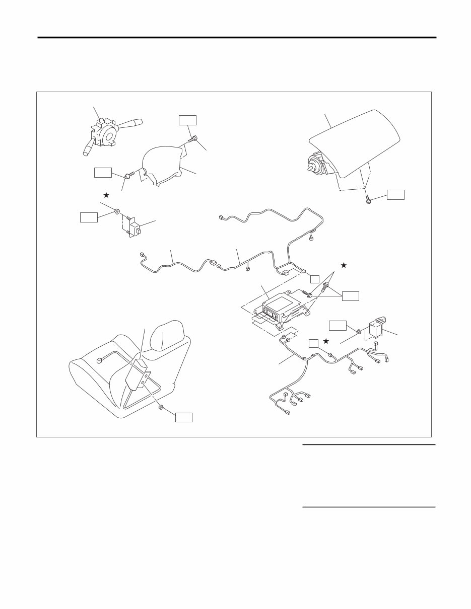
AB-2 General Description AIRBAG SYSTEM 1. General Description A: COMPONENT 1. SRS AIRBAG (1) Combination switch ASSY with roll connector (7) Wiring harness rear Tightening torque:N·m (kgf-m, ft-lb) (8) Side airbag module T1: 7.5 (0.8, 5.5) (2) TORX ® bolt T30 (9) Wiring harness center T2: 7.4 (0.75, 5.4) (3) Airbag module ASSY (Driver) (10) Wiring harness front T3: 10 (1.0, 7.2) (4) Airbag module ASSY (Passenger) (11) Front sub sensor T4: 20 (2.0, 14.5) (5) Airbag control module (12) Nut T5: 25 (2.5, 18.1) (6) Side airbag sensor (13) Bolt T3 T2 T5 T3 T4 (2) (4) (3) (1) (2) (10) (11) (12) (9) (6) (5) (8) (13) T2 T1 (7) (12) A A AB-01533
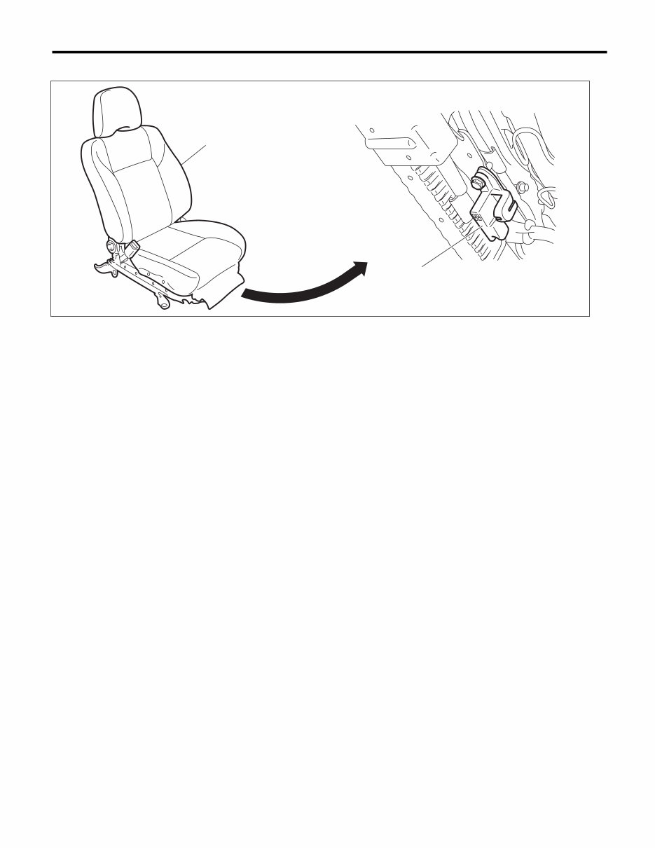
AB-3 General Description AIRBAG SYSTEM 2. SEAT POSITION SENSOR (1) Driver’s seat (2) Seat position sensor AB-01468 (1) (2)
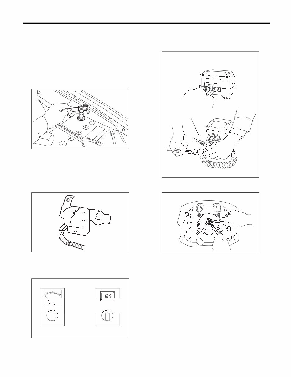
AB-4 General Description AIRBAG SYSTEM B: CAUTION • When servicing a vehicle, be sure to turn the ig- nition switch to OFF, disconnect the ground cable from battery, and wait for more than 20 seconds before starting work. • The airbag system is fitted with a backup power source. Be careful that the airbag may deploy after disconnecting the battery ground cable, if you do not wait for more than 20 seconds before starting the service of airbag system. • If the airbag warning light illuminates, repair the vehicle immediately. Be careful that the airbag or pretensioner may inflate incorrectly, or not inflate in collision without repair. • If sensors, airbag module, airbag control module, pretensioner or harness is deformed or damaged, replace with new parts. • When checking the airbag system, be sure to use a digital circuit tester. Use of an analog circuit tester may cause the airbag to activate erroneously due to a minimal current inside tester. • When checking, use a test harness (1). Damage to connector terminal cause malfunction. Do not di- rectly apply the tester probe to connector terminal of airbag. • Do not check continuity of the airbag modules for driver’s side, passenger’s side, or pretensioner. FU-00009 NG N N NG NG N N N G G G G G N N N N N N G NG G G G G N N N N N N N N N N N N G AB-01534 NG NG NG NG NG NG N NG N OK OK OK OK K O OK O AB-01535 AB-01536 (1) NG NG G G G G G N N NG G G G G G G G G N G G N N N NG N G OK OK O K OK K K O O O O O O O O O O K K O O O O O O O O O O O OK O O O O K K K K K K O O O O O O O O O O O O O O O OK OK O K K K OK K K K K O NG NG NG NG N N NG G NG NG NG NG NG N N N N N N N N N N N N N N N N N N N G G N N N N G NG G G G G G N N NG G G N N G G NG G G G G G G G G G G G G G G G G G G AB-01537
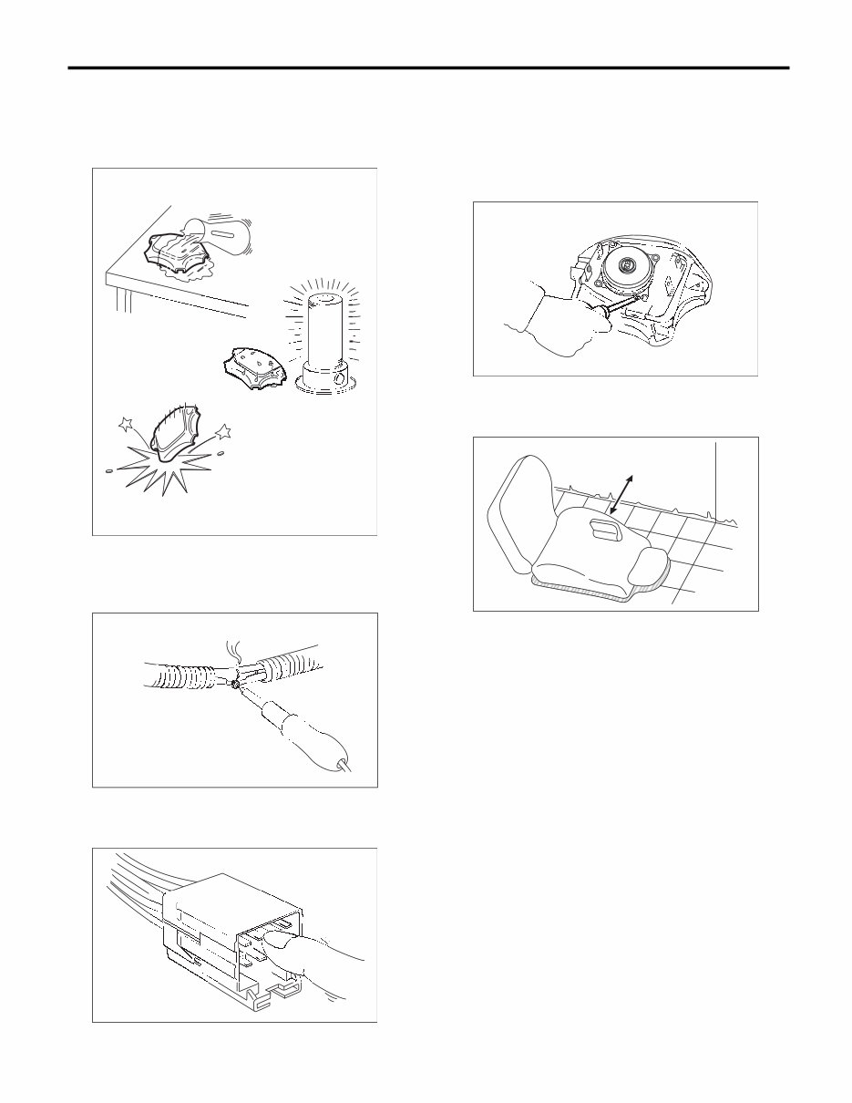
AB-5 General Description AIRBAG SYSTEM • Do not drop any parts of the airbag system, sub- ject them to high temperature over 93°C (199°F), or let water, oil or grease get on them; the internal parts may be damaged and reliability greatly low- ered. • If damage, open circuit or rust is found on airbag system wiring harness, do not use a soldering equipment to repair. Replace the faulty harness with a new genuine part. • Do not allow water or oil to come in contact with the connector terminals. Also, do not touch the con- nector terminals. • When airbag control module, front sub sensor, side airbag sensor and curtain airbag sensor are removed, do not reuse the bolts and nuts. Always use new bolts and nuts. • Either of the airbag modules for driver’s, passen- ger’s and side or the pretensioner must not be dis- assembled. • The removed front seat with airbag module must be kept at least 200 mm (8 in) away from walls and other objects. • Do not use the airbag or pretensioner parts from other vehicles. Always replace the defective parts with new parts. • Never reuse a deployed airbag and pretension- er. • When painting or performing sheet metal work on the front part of the vehicle, including the front wheel apron, front fender and front side frame, re- move the front sub sensors and wiring harness of airbag system. AB-01538 NG G G G G G G G G G G G G G G G G G G G G G G G G G G G G G G G G G G G G G G G G G G G G G G G G N N N N NG NG N N N NG G G G G G G G G G G G G G G G G G G G N G G N N G G N N N N N N N N N NG N N N N N N G G G G AB-01539 AB-01540 G G NG G G G G G G G G G G G G G G G G G G G G G G G G G G G G NG N N N N N N N N N N N N G N N N N N N N N NG N N N N G G G G G (1) 200 mm (8 in) or more AB-01541 NG NG N G G G N N N N N N N NG G G G G G G G G G G G G G G G G G G G G G G G G G G G G G G G G G G G G G G G G G G G G G N G G G G G G G G G G G G G G G G G N N N N N N N N N N N N G G G G G G G G N G G G G NG NG NG AB-00128 (1)
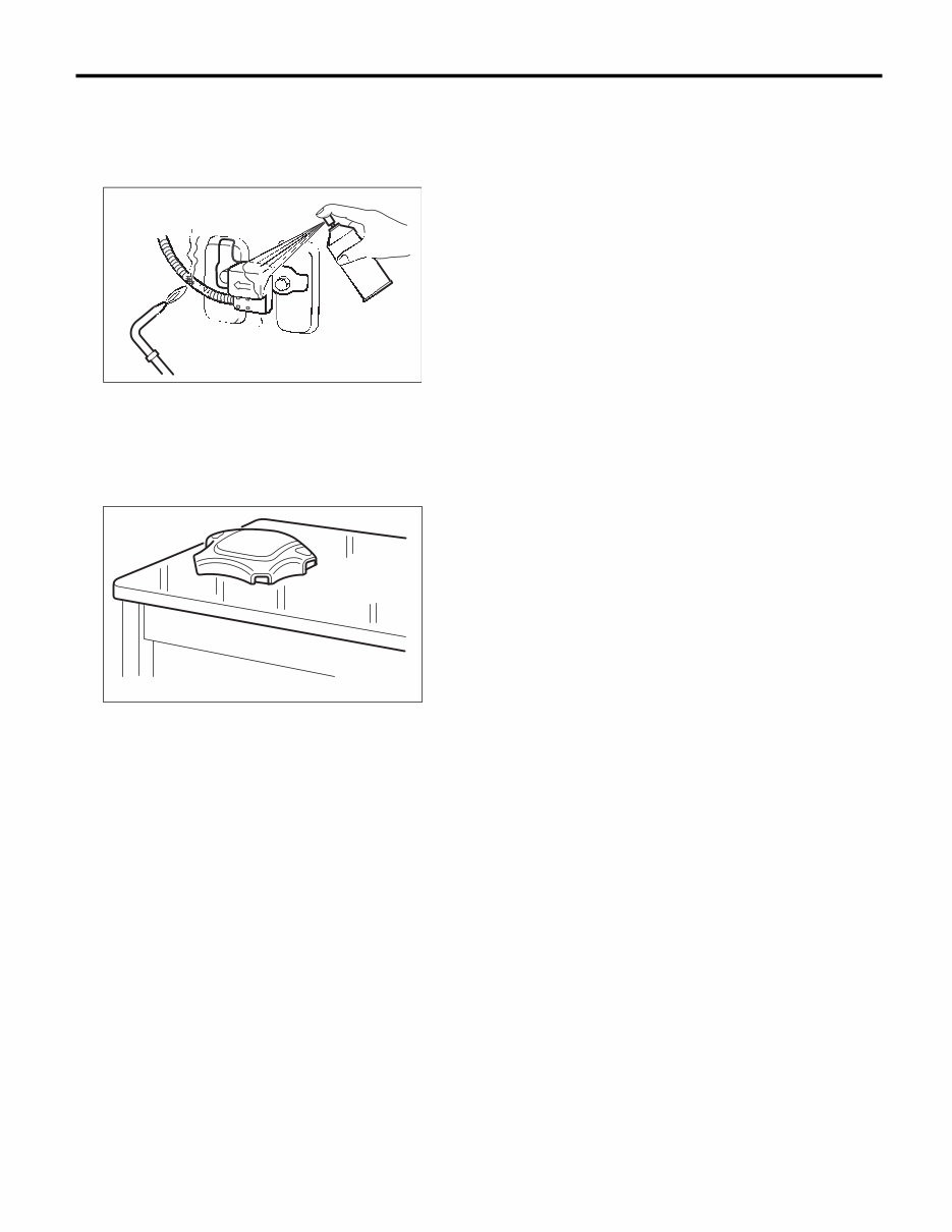
AB-6 General Description AIRBAG SYSTEM • When painting or performing sheet metal work on the side of the vehicle, including the side sill, center pillar and front and rear doors, remove the side airbag sensors and wiring harness of the air- bag system. • Do not discard an undeployed airbag module or pretensioner. • After removing the parts of airbag system, keep them with the pad facing upward on a dry, clean, and flat surface away from heat and light sources, and moisture and dust. • When airbag control module, front sub sensor and side airbag sensor are removed, do not reuse the bolts and nuts. Always use new bolts and nuts. AB-01542 NG N N NG N N N N N N N N N G G G G G G G G G N G G NG G G G G G G NG N N N N G G G G G G G N N N AB-00056
The 2007 Subaru Forester Service Repair Manual is a comprehensive guide designed to assist with repair, maintenance, rebuilding, refurbishing, or restoring the 2007 Subaru Forester. It includes complete step-by-step instructions, diagrams, illustrations, wiring schematics, and specifications for repair and troubleshooting.
This manual is tailored for both do-it-yourself enthusiasts and experienced mechanics. It provides detailed instructions along with exploded pictures and diagrams to ensure the correct and efficient completion of the required tasks.
The general index of the manual covers the following sections:
AUTOMATIC TRANSMISSION
BODY AND ELECTRICAL SECTION
Body and Exterior
Body Electrical System
Doors and Windows
Engine Electrical System
Instrument Panel
Seats, Seat Belts and Interior
Supplemental Restraint System
Clutch
Emission Control System and Vacuum Fitting
Engine
Engine and Transmission Mounting System
Engine Cooling System
Engine Lubrication System
Exhaust System
Fuel System
On-Car Services
Fuel Injection System
On-Board Diagnostics II System
GENERAL INFORMATION SECTION
Foreword
General Information
Periodic Maintenance Services
Pre-Delivery Inspection
Special Tools
Specifications
Air Conditioning System
Brakes
Heater and Ventilator
Pedal System and Control Cables
Steering System
Suspension
Wheels and Axles
Automatic Transmission and Differential
AWD System
Manual Transmission and Differential
Transmission Control System
WIRING DIAGRAM SECTION
Language: English
Printable: Yes
File Format: PDF
Compatibility: WINDOWS and MAC
Requirements: Adobe Reader
No shipping costs or waiting for a paper or CD manual to arrive in the mail. You will receive this manual instantly.