2006 Subaru Forester (SG) Service and Repair Manual
What's Included?
Lifetime Access
Fast Download Speeds
Offline Viewing
Access Contents & Bookmarks
Full Search Facility
Print one or all pages of your manual
4AT(D)(diag)-2 Basic Diagnostic Procedure AUTOMATIC TRANSMISSION (DIAGNOSTICS) 1. Basic Diagnostic Procedure A: PROCEDURE Step Check Yes No 1 CHECK PRE-INSPECTION. 1) Ask the customer when and how the trouble occurred using the interview check list. <Ref. to 4AT(D)(diag)-4, Check List for Interview.> 2) Before performing diagnosis, inspect the fol- lowing items which may influence AT problems. • General Inspection <Ref. to 4AT(D)(diag)-5, INSPECTION, General Description.> • Disconnection of harness connector • Visual check for harness damage • Oil leakage • Stall speed test <Ref. to 4AT-32, Stall Test.> • Line pressure test <Ref. to 4AT-34, Line Pres- sure Test.> • Transfer clutch pressure test <Ref. to 4AT-36, Transfer Clutch Pressure Test.> • Time lag test <Ref. to 4AT-33, Time Lag Test.> • Road test <Ref. to 4AT-31, Road Test.> • Inhibitor switch <Ref. to 4AT-47, Inhibitor Switch.> Is the unit that is thought to influence the AT problem work- ing properly? Go to step 2. Repair or replace each item. 2 CHECK AT OIL TEMP WARNING LIGHT. Turn the ignition switch to ON. Does the AT OIL TEMP warn- ing light illuminate? Go to step 4. Go to step 3. 3 CHECK AT OIL TEMP WARNING LIGHT. 1) Turn the ignition switch to OFF. 2) Repair the AT OIL TEMP warning light cir- cuit or power supply and ground line circuit. <Ref. to 4AT(D)(diag)-20, AT OIL TEMP Warn- ing Light Display.> 3) Turn the ignition switch to ON. Is the AT OIL TEMP warning light flashing? Go to step 4. Go to step 5. 4 CHECK INDICATION OF DTC. Display the DTC. NOTE: If the communication function of Subaru Select Monitor cannot be executed normally, check the communication circuit. <Ref. to 4AT(D)(di- ag)-25, COMMUNICATION FOR INITIALIZING IMPOSSIBLE, Diagnostic Procedure for Suba- ru Select Monitor Communication.> Is DTC displayed? Go to step 6. NOTE: Record all DTC. Go to step 5. 5 PERFORM GENERAL DIAGNOSTICS. 1) Inspect using “Diagnostic Procedure with- out Diagnostic Trouble Code (DTC)”. <Ref. to 4AT(D)(diag)-87, Diagnostic Procedure without Diagnostic Trouble Code (DTC).> 2) Inspect using “General Diagnostic Table”. <Ref. to 4AT(D)(diag)-90, General Diagnostic Table.> 3) Perform the Clear Memory Mode. 4) Perform the Inspection Mode. <Ref. to 4AT(D)(diag)-18, Inspection Mode.> 5) Display the DTC. Is DTC displayed? Go to step 6. Finish the diagno- sis.
4AT(D)(diag)-3 Basic Diagnostic Procedure AUTOMATIC TRANSMISSION (DIAGNOSTICS) 6 PERFORM DIAGNOSIS. 1) Inspect using the “Diagnostic Procedure with Diagnostic Trouble Code (DTC)”. <Ref. to 4AT(D)(diag)-31, Diagnostic Procedure with Diagnostic Trouble Code (DTC).> NOTE: For DTC table, refer to “List of Diagnostic Trou- ble Code (DTC)”. <Ref. to 4AT(D)(diag)-29, List of Diagnostic Trouble Code (DTC).> 2) Repair the trouble cause. 3) Perform the Clear Memory Mode. 4) Perform the Inspection Mode. <Ref. to 4AT(D)(diag)-18, Inspection Mode.> 5) Display the DTC. Is DTC displayed? Inspect using the “Diagnostic Proce- dure with Diagnos- tic Trouble Code (DTC)”. <Ref. to 4AT(D)(diag)-31, Diagnostic Proce- dure with Diagnos- tic Trouble Code (DTC).> Finish the diagno- sis. Step Check Yes No
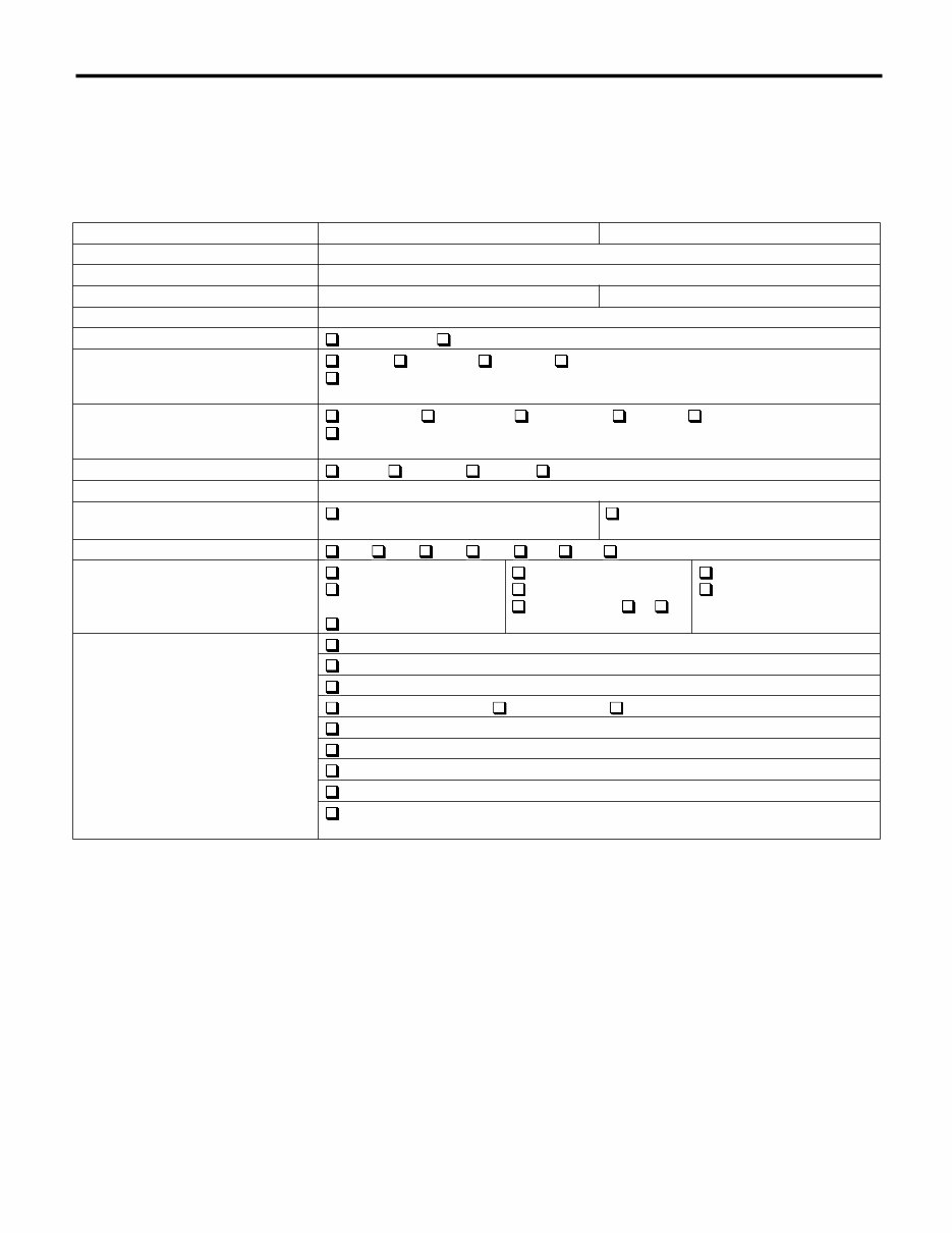
4AT(D)(diag)-4 Check List for Interview AUTOMATIC TRANSMISSION (DIAGNOSTICS) 2. Check List for Interview A: CHECK Check the following items when a problem has occurred. NOTE: Use copies of this page for interviewing customers. Customer’s name Date of purchase Date of repair Transmission model Transmission V.I.N. Odometer reading km (miles) Frequency Continuous Intermittent ( times a day) Weather Fine Cloudy Rainy Snowy Others ( ) Place Highland Suburbs Inner city Uphill Rough road Others ( ) Ambient air temperature Hot Warm Cool Cold Vehicle speed km/h (MPH) AT OIL TEMP warning light (AT diag- nostic indicator light) Blinks continuously Does not blink Select lever position P R N D 3 2 1 Driving condition Not affected When revving at a stand- still While decelerating At starting While accelerating While turning ( R/ L) While idling While cruising Symptoms No up-shift No down-shift No kick down Vehicle does not move ( Any position Particular position) Lock-up malfunction Noise or vibration Shift shock or slip Select lever does not move Others ( )
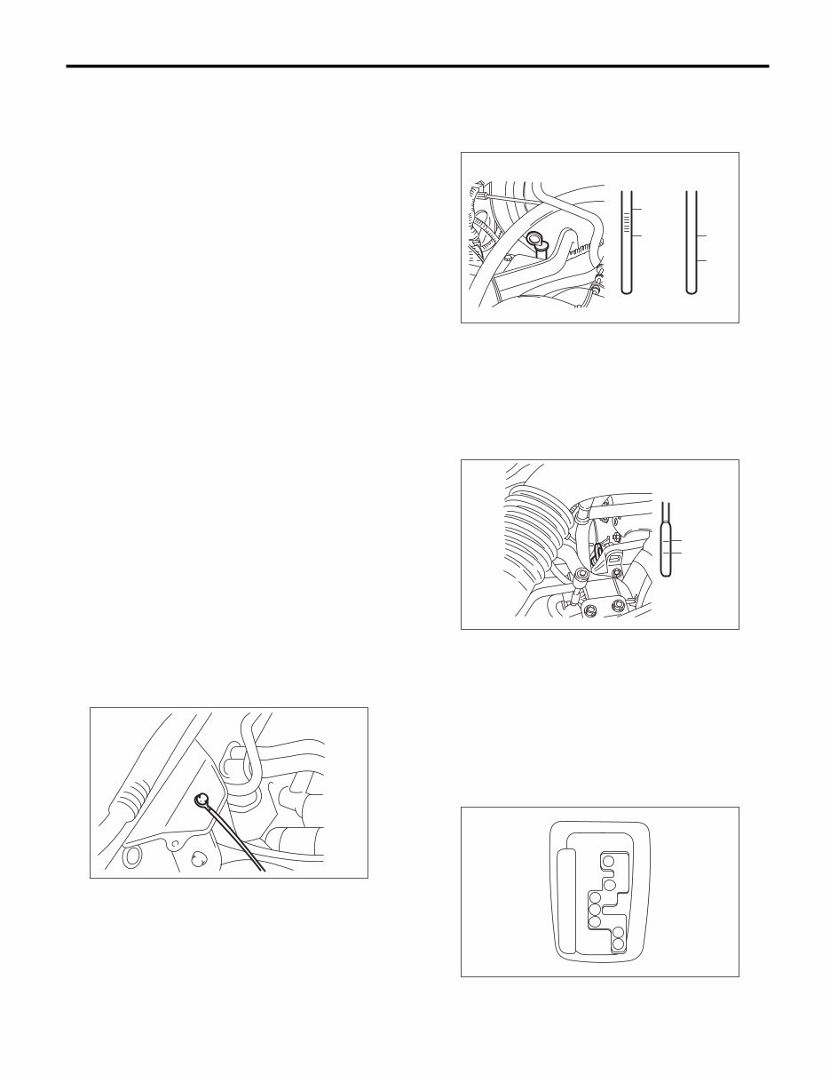
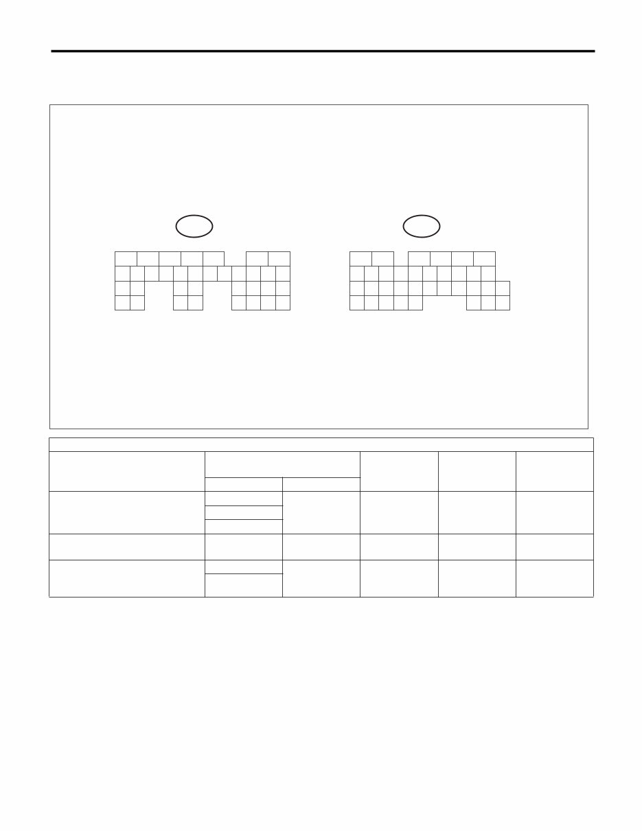
4AT(D)(diag)-5 General Description AUTOMATIC TRANSMISSION (DIAGNOSTICS) 3. General Description A: CAUTION 1. SUPPLEMENTAL RESTRAINT SYSTEM “AIRBAG” The airbag system wiring harness is routed near the TCM. CAUTION: • The airbag system wiring harnesses and con- nectors are colored yellow. Do not use an elec- tric test equipment to check these circuits. • Be careful not to damage the airbag system wiring harness when performing TCM diagnos- tics or servicing. 2. MEASUREMENT When measuring the voltage and resistance of the ECM, TCM or each sensor, use a tapered pin with a diameter of less than 0.64 mm (0.025 in) in order to avoid poor contact. Do not insert a pin of more than 0.65 mm (0.026 in) diameter. B: INSPECTION 1. BATTERY Measure the battery voltage and specific gravity of the electrolyte. Standard voltage: 12 V or more Specific gravity: 1.260 or more 2. TRANSMISSION GROUND Check that the ground terminal bolt is tightened se- curely. Chassis side Tightening torque: 13 N·m (1.3 kgf-m, 9.4 ft-lb) 3. ATF LEVEL Check that the ATF level is at the specified amount. <Ref. to 4AT-28, INSPECTION, Automatic Trans- mission Fluid.> 4. FRONT DIFFERENTIAL OIL LEVEL Check the front differential oil level is the specified amount. <Ref. to 4AT-30, INSPECTION, Differen- tial Gear Oil.> 5. OPERATION OF SELECT LEVER Check there is no noise, dragging or contact pat- tern in each select lever range. WARNING: Stop the engine while checking operation of the select lever. AT-00315 (A) Upper level (B) Lower level (A) Upper level (B) Lower level AT-00316 (B) (B) (A) (A) O F O F O L O L O O HOT COLD AT-00317 (A) (B) L F AT-00413 P R N D 3 2 1
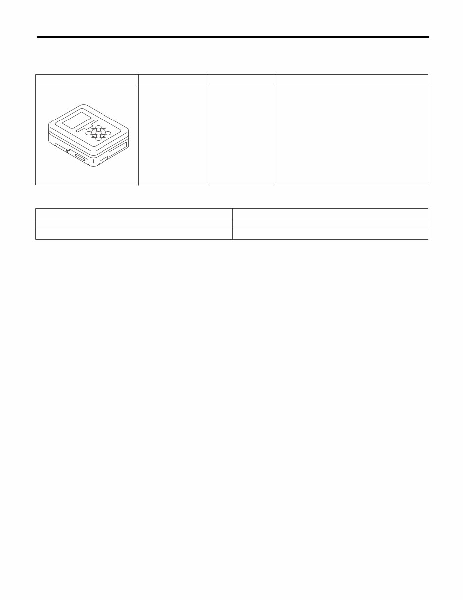
4AT(D)(diag)-6 General Description AUTOMATIC TRANSMISSION (DIAGNOSTICS) C: PREPARATION TOOL 1. SPECIAL TOOL 2. GENERAL TOOL ILLUSTRATION TOOL NUMBER DESCRIPTION REMARKS 1B020XU0 SUBARU SELECT MONITOR KIT Troubleshooting the electrical system. TOOL NAME REMARKS Circuit tester Used for measuring resistance, voltage and current. Oscilloscope Used for measuring the sensor. ST1B020XU0
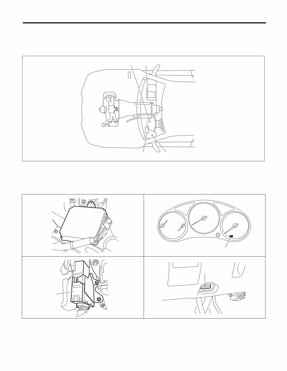
4AT(D)(diag)-7 Electrical Component Location AUTOMATIC TRANSMISSION (DIAGNOSTICS) 4. Electrical Component Location A: LOCATION 1. CONTROL MODULE (1) Engine control module (ECM) (3) Transmission control module (TCM) (4) Data link connector (2) AT OIL TEMP warning light (AT diagnostic indicator light) AT-00414 (1) (2) (3) (4) AT-00323 (1) (2) AT-00415 AT-03375 (3) (4) AT-00417
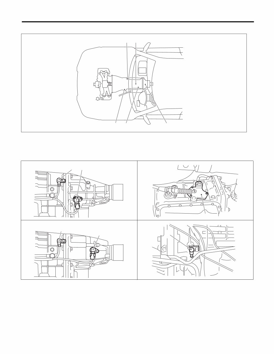
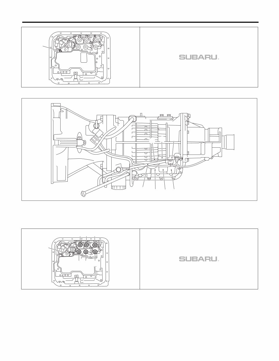
4AT(D)(diag)-8 Electrical Component Location AUTOMATIC TRANSMISSION (DIAGNOSTICS) 2. SENSOR (1) Front vehicle speed sensor (3) Rear vehicle speed sensor (5) ATF temperature sensor (2) Inhibitor switch (4) Torque converter turbine speed sensor AT-03376 (1) (2) (3) (4) (5) AT-04301 (1) (3) MODEL WITH MP-T AT-03379 (2) AT-03378 (1) (3) WITH VTD MODEL AT-03380 (4)
4AT(D)(diag)-11 Transmission Control Module (TCM) I/O Signal AUTOMATIC TRANSMISSION (DIAGNOSTICS) Inhibitor switch “P” range switch (B54) No. 14 Chassis ground Selector lever in “P” range Less than 1 — Selector lever in any other than “P” range 8 or more “R” range switch (B54) No. 13 Chassis ground Selector lever in “R” range Less than 1 — Selector lever in any other than “R” range 8 or more “N” range switch (B54) No. 11 Chassis ground Selector lever in “N” range Less than 1 — Selector lever in any other than “N” range 8 or more “D” range switch (B54) No. 10 Chassis ground Selector lever in “D” range Less than 1 — Selector lever in any other than “D” range 8 or more “3” range switch (B54) No. 8 Chassis ground Selector lever in “3” range Less than 1 — Selector lever in any other than “3” range 8 or more “2” range switch (B54) No. 7 Chassis ground Selector lever in “2” range Less than 1 — Selector lever in any other than “2” range 8 or more “1” range switch (B54) No. 19 Chassis ground Selector lever in “1” range Less than 1 — Selector lever in any other than “1” range 8 or more Brake switch (B54) No. 20 Chassis ground When brake pedal is depressed. 10.5 or more — When brake pedal is released. Less than 1 ATF temperature sensor (B54) No. 23 (B54) No. 12 ATF tempera- ture 20°C (68°F) 3.5 — 4.3 2.5 k — 7 k ATF tempera- ture 80°C (176°F) 1.0 — 2.2 300 — 800 ATF temperature sensor ground (B54) No. 12 Chassis ground — 0 Less than 1 Rear vehicle speed sensor (B54) No. 26 (B54) No. 15 Vehicle stopped 0 — Vehicle speed at least 20 km/h (12 MPH) More than 2 (AC range) Rear vehicle speed sensor ground (B54) No. 15 Chassis ground — 0 Less than 1 Check with ignition switch ON. Contents Measured terminal (Connector & Terminal No.) Measuring con- dition Voltage (V) Resistance (Ω) Positive terminal Ground terminal
Get your hands on the 2006 Subaru Forester (SG) Service and Repair Manual. These Auto Repair Manuals provide comprehensive instructions and procedures for fixing problems in your vehicle. Whether you're a professional mechanic or a DIY enthusiast, these manuals can be invaluable for immediate car repairs and the long-term maintenance of your vehicle.
With detailed technical data, diagrams, and a complete list of car parts, these manuals are designed to be user-friendly for both novice and experienced car mechanics. The step-by-step guides are accompanied by illustrations and drawings, making the repair process straightforward.
The manual covers a wide range of sections including maintenance, engine, control system, mechanical, fuel service specifications, emission control, and much more. It also includes wiring schematics and specifications to facilitate easy vehicle repair.
These repair manuals are available in .PDF format for easy access and compatibility with all versions of Windows and Mac. You can print specific pages and diagrams as needed, ensuring that you have the necessary information at hand whether you're working on your vehicle in the garage or workshop.
By having a trusty repair manual, you not only save money on car repairs but also gain the satisfaction of completing do-it-yourself projects. The manuals also provide a complete list of accessories that can enhance your engine's performance.
Experience the convenience of having all the car information you need at your fingertips. Say goodbye to relying solely on your mechanic for even the simplest car repairs. Embrace the fun and empowerment of taking care of your vehicle with these comprehensive repair manuals.
Don't miss out on the opportunity to keep your vehicle in top condition and expand your knowledge of car maintenance and repair. These Auto Repair Manuals are a valuable resource for anyone looking to take a hands-on approach to caring for their vehicle.
Maintenance
Engine
Control System
Mechanical
Fuel Service Specifications
Emission Control
Intake Exhaust Cooling
Lube
Ignition Starting Charging
Auto Transmission Clutch
Manual Transmission
Transfer Propeller Shaft
Drive Shaft
Differential
Axle Suspension
Tire & Wheel
Brake Control
Brake
Parking Brake
Steering Column
Power Steering
Air Condition
Suppl Restraint System
Seat Belt
Engine Immobilizer
Cruise Control
Wiper & Washer
Door Lock
Meter Audio/Visual
Horn
Windshield/Glass Mirror
Instrument Panel
Seat
Engine Hood/Door
Exterior & Interior
Electrical
Multiplex/Can Communication
And much more...
These manuals are designed to provide you with everything you need to maintain, service, diagnose, and repair your vehicle with ease. Take advantage of the detailed instructions, illustrations, and wiring schematics to keep your vehicle in top condition.
Compatible with all versions of Windows and Mac, these repair manuals are a must-have for anyone looking to enhance their car repair knowledge and take control of their vehicle's maintenance.
Recently Viewed
5,521,897Happy Clients
2,594,462eManuals
1,120,453Trusted Sellers
15Years in Business
Price:
Actual Price:
2006 Subaru Forester (SG) Service and Repair Manual