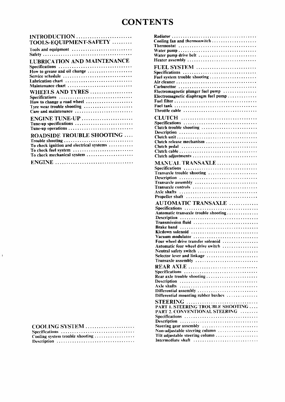
CONTENTS INTRODUCTION. ........................ 7 TOOLS-EQUIPMENT-SAFETY......... 8 Tools and equipment 8 Safety ........................................ 10 LUBRICATION AND MAINTENANCE 11 Specifications 11 How to grease and oil change 11 Service schedule 14 Lubrication chart 19 Maintenance chart 20 WHEELS AND TYRES 21 Specifications ........ • ........................ 21 How to change a road wheel 21 Tyre wear trouble shooting 23 Care and maintenance 24 ENGINE TUNE-UP. .. .................... 25 Tune-up specifications 25 Tune-up operations ............................. 25 ROADSIDE TROUBLE SHOOTING. ... 33 Trouble shooting ............................... 33 To check ignition and electrical systems 33 To check fuel system 35 To check mechanical system. .................... 36 ENGINE 38 PART 1. ENGINE MECHANICAL TROUBLE SHOOTING. ................................. 38 PART 2. OVERHEAD VALVE (OHV) ENGINE .. 41 Specifications ; ..................... 41 Description 43 Engine assembly ............................... 43 Rocker assemblies and pushrods 46 Inlet manifold 47 Engine sump and oil pump pick up ................ 48 Camshaft and cam followers 49 Cylinder heads 50 Oil pump ..................................... 53 Pistons, connecting rods and cylinder bores 54 Crankshaft and main bearings 60 Flywheel/drive plate ............................ 62 Engine mountings .............................. 63 Exhaust system ................................ 64 PART. 3 OVERHEAD CAMSHAFT (OHC) ENGINE ..................................... 66 Specifications 66 Description c • • • • • • • • • • • • • • • • • • • • • • 67 Engine assembly ............................... 68 Camshaft drive belts. ........................... 71 Camshafts, rocker arms and tappets 75 Inlet manifold 76 Cylinder heads 77 Engine sump and oil pump pick up ................ 80 Oil pump ..................................... 81 Pistons, connecting rods and cylinder bores 82 Crankshaft and main bearings 88 Flywheel/drive plate ................... 90 Engine mountings. ............................. 91 Exhaust system ................................ 92 COOLING SySTEM...................... 93 Specifications 93 Cooling system trouble shooting. ................. 93 Description 94 Radiator ...................................... 95 Cooling fan and thermoswitch .................... 97 Thermostat 98 Water pump ................................... 99 Water pump drive belt. .................... .. .. . 100 Heater assembly. .............................. 100 FUEL SYSTEM 104 Specifications 104 Fuel system trouble shooting. .................... 104 Air cleaner .................................... 106 Carburettor 107 Electromagnetic plunger fuel pump 116 Electromagnetic diaphragm fuel pump ............. 117 Fuel filter. .................................... 119 Fuel tank ..................................... 119 Throttle cable 120 CLUTCH 121 Specifications 121 Clutch trouble shooting 121 Description 122 Clutch unit. ................................... 123 Clutch release mechanism ....................... 124 Clutch pedal 125 Clutch cable. .................................. 125 Clutch adjustments ............................. 126 MANUAL TRANSAXLE .................. 127 Specifications 127 Transaxle trouble shooting 128 Description 132 Transaxle assembly 135 Transaxle controls 141 Axle shafts 148 Propeller shaft 150 AUTOMATIC TRANSAXLE 152 Specifications 152 transaxle trouble shooting. ............. 152 DescrIptIon 153 Transmission fluid 153 Brake band 154 Kicdown solenoid 155 Vacuum modulator. ............................ 155 Four wheel drive transfer solenoid 155 Automatic four wheel drive switch 156 Neutral safety switch 156 Selector lever and linkage 157 Transaxle assembly 159 REAR AXLE ............................... 162 Specifications 162 Rear axle trouble shooting. ...................... 162 Description 164 Axle shafts 165 Differential assembly. .......................... 166 Differential mounting rubber bushes 168 STEERING ................................ 170 PART 1. STEERING TROUBLE SHOOTING.... 170 PART 2. CONVENTIONAL STEERING In Specifications In Description 1n Steering gear assembly 1n Non-adjustable steering column 174 Tilt adjustable steering column. .................. 176 Intermediate shaft 178
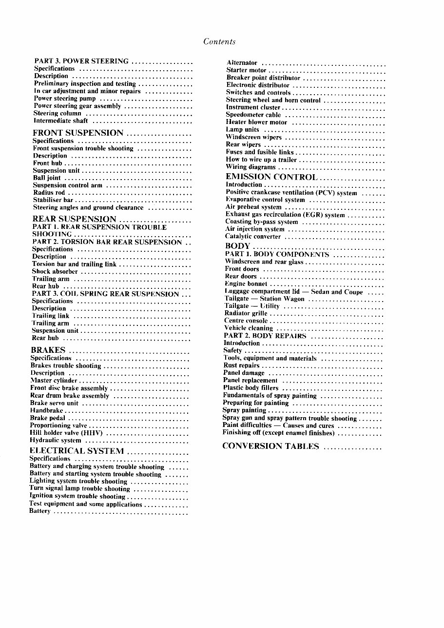
Contents .. PART 3. POWER STEERING.................. 179 Specifications 179 Description 179 Preliminary inspection and testing ................ 179 In car adjustment and minor repairs 180 Power steering pump 181 Power steering gear assembly 183 Steering column 184 Intermediate shaft 184 FRONT SUSPENSION.. .. .. .. .. .. .. . 185 Specifications 185 Front suspension trouble shooting 185 Description 186 Front hub ..................................... 187 Suspension unit. ............................... 188 Ball joint 190 Suspension control arm. ..... .. .. .. .... .. .. .. .. . 190 Radius rod .................................... 190 Stabiliser bar. ................. .. .... .. .. ...... 191 Steering angles and ground clearance 191 REAR SUSPENSION. .................... 194 PART 1. REAR SUSPENSION TROUBLE SHOOTING. ................................. 194 PART 2. TORSION BAR REAR SUSPENSION.. 195 Specifications 195 Description 195 Torsion bar and trailing link. .................... 195 Shock absorber. ............................... 196 Trailing arm 197 Rear hub 197 PART 3. COIL SPRING REAR SUSPENSION... 198 Specifications 198 Description 198 Trailing link 198 Trailing arm 198 Suspension unit. ............................... 199 Rear hub 200 BRAKES 203 Specifications 203 Brakes trouble shooting ......................... 203 Description 206 Master cylinder ................................ 206 Front disc brake assembly. ..• ................... 208 Rear drum brake assembly 212 Brake servo unit 214 Handbrake. ................................... 215 Brake pedal. .................................. 216 Proportioning valve............................. 217 Hill holder valve (HHV) 217 Hydraulic system 218 ELECTRICAL SYSTEM. ................. 219 Specifications 219 Battery and charging system trouble shooting 219 Battery and starting system trouble shooting 221 Lighting system trouble shooting 221 Turn signal lamp trouble shooting 222 Ignition system trouble shooting. ................. 223 Test equipment and some applications. ............ 223 Battery .. ..................................... 224 Alternator 225 Starter motor. ................................. 229 Breaker point distributor. ....................... 232 Electronic distributor ............. 235 Switches and controls ........................... 239 Steering wheel and horn control ............ 242 Instrument cluster. ............................. 242 Speedometer cable 244 Heater blower motor 244 Lamp units 245 Windscreen wipers. ............................ 251 Rear wipers 252 Fuses and fusible links. ......................... 253 How to wire up a trailer ......................... 254 Wiring diagrams ............................... 256 EMISSION CONTROL. .................. 272 Introduction ................................... 272 Positive crankcase ventilation (PCV) system 272 Evaporative control system 273 Air preheat system 277 Exhaust gas recirculation (EGR) system. .......... 277 Coasting by-pass system 280 Air injection system 281 Catalytic converter 282 BODy 283 PART 1. BODY COMPONENTS ............... 283 Windscreen and rear glass. ...................... 283 Front doors 283 Rear doors ................................. 286 Engine bonnet ................................. 289 Luggage compartment lid - Sedan and Coupe 290 Tailgate - Station Wagon 291 Tailgate - Utility 293 Radiator grille ................................. 294 Centre console. ................................ 294 Vehicle cleaning 294 PART 2. BODY REPAIRS ..................... 297 Introduction ................................... 297 Safety .................................. 297 Tools, equipment and materials 297 Rust repairs ................................... 302 Panel damage 305 Panel replacement 308 Plastic body fillers 309 Fundamentals of spray painting 310 Preparing for painting 313 Spray painting. ................................ 316 Spray gun and spray pattern trouble shooting. ...... 318 Paint difficulties - Causes and cures. ............ 319 Finishing off (except enamel finishes) 323 CONVERSION TABLES 325 SUPPLEMENT 327 Lubrication, maintenance and engine tune-up " 328 Overhead camshaft engine 328 Fuel system 328 Front suspension 328 Rear suspension 328 Emission control 328
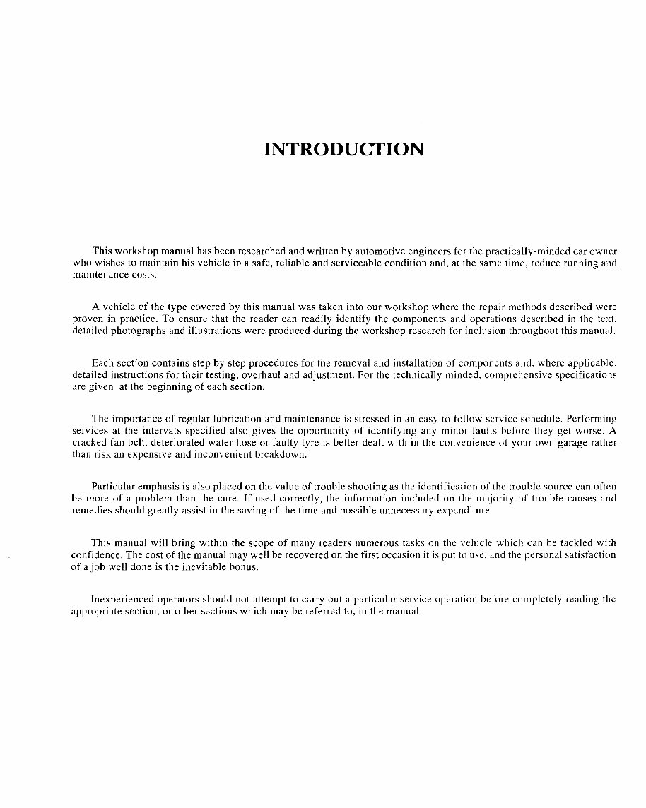
INTRODUCTION This workshop manual has been researched and written by automotive engineers for the practically-minded car owner who wishes to maintain his vehicle in a safe, reliable and serviceable condition and, at the same time, reduce running and maintenance costs. A vehicle of the type covered by this manual was taken into our workshop where the repair methods described were proven in practice. To ensure that the reader can readily identify the components and operations described in the text, detailed photographs and illustrations were produced during the workshop research for inclusion throughout this manual. Each section contains step by step procedures for the removal and installation of components and, where applicable, detailed instructions for their testing, overhaul and adjustment. For the technically minded, comprehensive specificatiol1s are given at the beginning of each section. The importance of regular lubrication and maintenance is stressed in an easy to follow service schedule. Performing services at the intervals specified also gives the opportunity of identifying any minor faults before they get worse. A cracked fan belt, deteriorated water hose or faulty tyre is better dealt with in the convenience of your own garage rather than risk an expensive and inconvenient breakdown. Particular emphasis is also placed on the value of trouble shooting as the identification of the trouble source can often be more of a problem than the cure. If used correctly, the information included on the majority of trouble causes and remedies should greatly assist in the saving of the time and possible unnecessary expenditure. This manual will bring within the scope of many readers numerous tasks on the vehicle which can be tackled with confidence. The cost of the manual may well be recovered on the first occasion it is put to usc, and the personal satisfaction of a job well done is the inevitable bonus. Inexperienced operators should not attempt to carry out a particular service operation before completely reading the appropriate section, or other sections which may be referred to, in the manual.
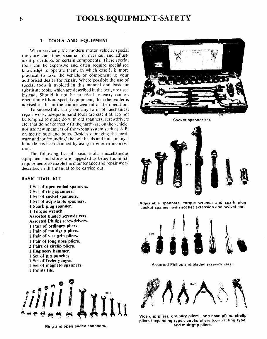
8 TOOLS-EQUIPMENT-SAFETY 1 .; I I Assorted Philips and bladed screwdrivers. Socket spanner set. BC/5 Adjustable spanners, torque wrench and spark plug socket spanner with socket extension and swivel bar. 1. TOOLS AND EQUIPMENT 1 Set of open ended spanners. 1 Set of ring spanners. 1 Set of socket spanners. 1 Set of adjustable spanners. 1 Spark plug spanner. 1 Torque wrench. Assorted bladed screwdrivers. Assorted Philips screwdrivers. 1 Pair of ordinary pliers. 1 Pair of multigrip pliers. 1 Pair of vice grip pliers. 1 Pair of long nose pliers. 2 Pairs of circlip pliers. 1 Engineers hammer. 1 Set of pin punches. 1 Set of feeler gauges. 1 Set of magneto spanners. 1 Points file. When servicing the modern motor vehicle, special tools are sometimes essential for overhaul and adjust- ment procedures on certain components. These special tools can be expensive and often require specialised knowledge to operate them, in which case it is more practical to take the vehicle or component to your authorised dealer for repair. Where possible the use of special tools is avoided in this manual and basic or substitute tools, which are described in the text, are used instead. Should it not be practical to carry out an operation without special equipment, then the reader is advised of this at the commencement of the operation. To successfully carry out any form of mechanical repair work, adequate hand tools are essential. Do not be tempted to make do with old spanners, screwdrivers etc, that do not correctly fit the hardware on the vehicle, nor use new spanners of the wrong system such as A.F. on metric nuts and 601ts. Besides damaging the hard- ware and/or 'rounding' the bolt heads and nuts, many a knuckle has been skinned by using inferior or incorrect tools. The following list of basic tools, miscellaneous equipment and stores are suggested as being the initial requirements to enable the maintenance and repair work described in this manual to be carried out. BASIC TOOL KIT " Ring and open ended spanners. Vice grip pliers, ordinary pliers, long nose pliers, circlip pliers (expanding type), circlip pliers (contracting typel and multigrip pliers.
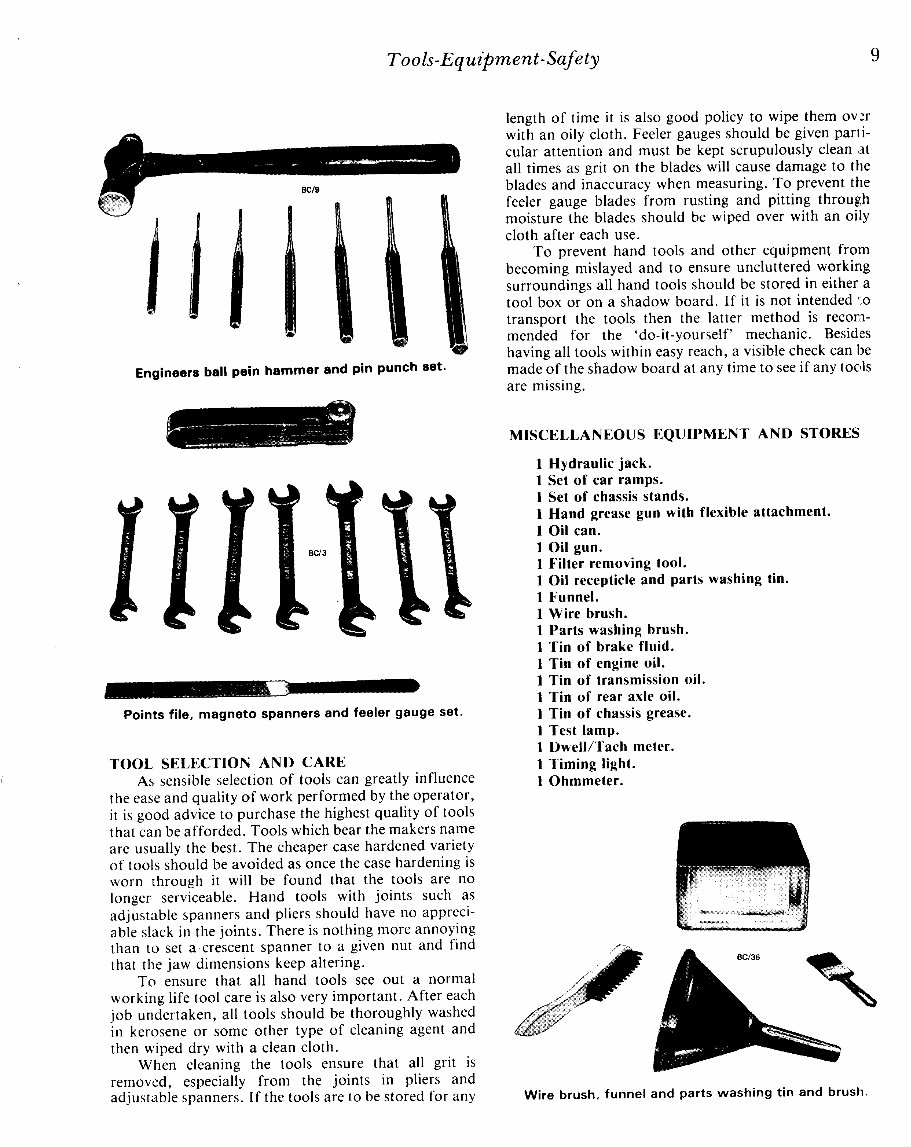
9 Tools-Eqwpment-Safety Engineers ball pein hammer and pin punch set. length of time it is also good policy to wipe them over with an oily cloth. Feeler gauges should be given parI i- cular attention and must be kept scrupulously clean at all times as grit on the blades will cause damage to the blades and inaccuracy when measuring. To prevent the feeler gauge blades from rusting and pitting through moisture the blades should be wiped over with an oily cloth after each use. To prevent hand tools and other equipment from becoming mislayed and to ensure uncluttered working surroundings all hand tools should be stored in either a tool box or on a shadow board. If it is not intended to transport the tools then the latter method is recom- mended for the 'do-it-yourself' mechanic. Besides having all tools within easy reach, a visible check can be made of the shadOW board at any time to see if any toe,ls are missing. """" -" ;" --- -" MISCELLANEOUS EQUIPMENT AND STORES Wire brush. funnel and parts washing tin and brush. 1 Hydraulic jack. 1 Set of car ramps. 1 Set of chassis stands. 1 Hand grease gun with flexible attachment. 1 Oil can. 1 Oil gun. 1 .'ilter removing tool. 1 Oil recepticle and parts washing tin. 1 .'unnel. 1 Wire brush. 1 Parts washing brush. 1 Tin of brake fluid. 1 Tin of engine oil. 1 Tin of transmission oil. 1 Tin of rear axle oil. 1 Tin of chassis grease. 1 Test lamp. 1 Dwell/Tach meter.. 1 Timing light. 1 Ohmmeter. Points file, magneto spanners and feeler gauge set. TOOL SELECTION AND CARE As sensible selection of tools can greatly influence the ease and quality of work performed by the operator, it is good advice to purchase the highest quality of tools that can be afforded. Tools which bear the makers name are usually the best. The cheaper case hardened variety of tools should be avoided as once the case hardening is worn through it will be found that the tools are no longer serviceable. Hand tools with joints such as adjustable spanners and pliers should have no appreci- able slack in the joints. There is nothing more annoying than to set a crescent spanner to a given nut and find that the jaw dimensions keep altering. To ensure that all hand tools see out a normal working life tool care is also very important. After each job undertaken, all tools should be thoroughly washed in kerosene or some other type of cleaning agent and then wiped dry with a clean cloth. When cleaning the tools ensure that all grit is removed, especially from the joints in pliers and adjustable spanners. If the tools are to be stored for any
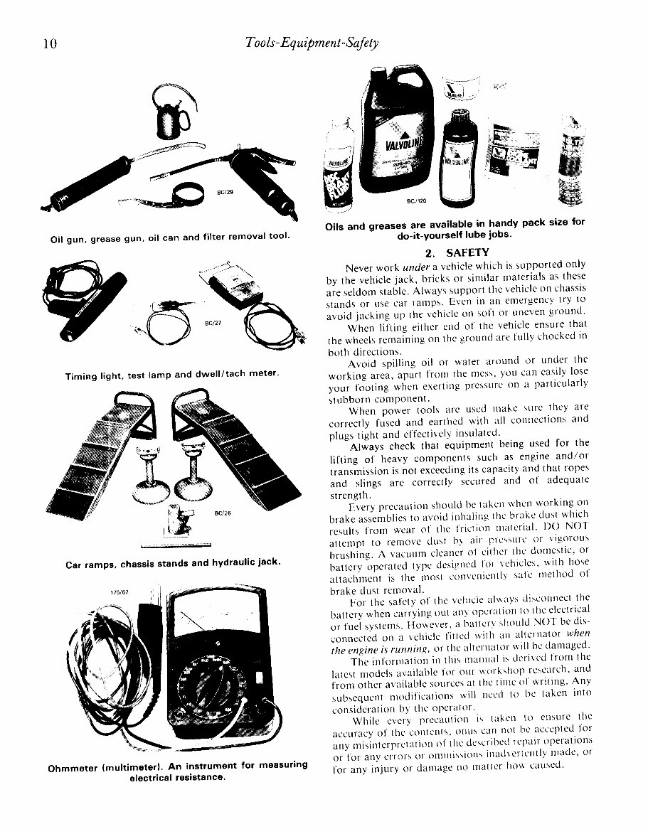
-------------_.------. 10 Too ls- Equipment-Safety Oils and greases are available in handy pack size for do-it-yourself lube jobs. 2. SAFETY Never work under a vehicle which is supported only by the vehicle jack, bricks or similar materials as these are seldom stable. Always support the vehicle on chassis stands or use car ramps. Even in an emergency try to avoid jacking up the vehicle on soft or uneven ground. When lifting either end of the vehicle ensure that the wheels remaining on the ground are fully chocked in both directions. Avoid spilling oil or water around or under the working area, apart from the mess, you can easily lose your footing when exerting pressure on a particularly stubborn component. When power tools are used make sure they are correctly fused and earthed with all connections and plugs tight and effectively insulated. Always check that equipment being used for the lifting of heavy components such as engine and/or transmission is not exceeding its capacity and that ropes and slings are correctly secured and of adequate strength. Every precaution should be taken when working on brake assemblies to avoid inhaling the brake dust which results from wear of the friction material. DO NOT attempt to remove dust by air pressure or vigorous brushing. A vacuum cleaner of either the domestic, or battery operated type designed for vehicles, with hose attachment is the most conveniently sate method of brake dust removal. For the safety of the vehicle always disconnect the battery when carrying out any operation to the electrical or fuel systems. However, a battery should NOT be dis- connected on a vehicle fitted with an alternator when the engine is running, or the alternator will be damaged. The information in this manual is derived from the latest models available for our workshop research, and from other available sources at the time of writing. Any subsequent modifications will need to be taken into consideration by the operator. While every precaution is taken to ensure the accuracy of the contents, onus can not be accepted for any misinterpretation of the described repair operations or for any errors or ommissions inadvertently made, or for any injury or damage no matter how caused. (5 \ '" ,," "Be/27 ," Car ramps. chassis stands and hydraulic jack. TimiFlg light. test lamp and dwell/tach meter. Oil gun. grease gun. oil can and filter removal tool. Ohmmeter (multimeterl. An instrument for measuring electrical resistance.
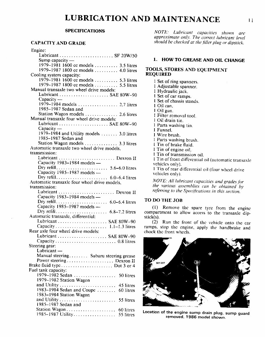
For later models refer to supplement. L UBRICA TION AND MAINTENANCE II SPECIFICATIONS CAPACITY AND GRADE Engine: Lubricant SF 20W/50 Sump capacity - 1979-1981 1600 cc models 3.5 litres 1979-1987 1800 cc models 4.0 litres Cooling system capacity: 1979-1981 1600 cc models 5.3litres 1979-1987 1800 cc models 5.51itres Manual transaxle two wheel drive models: Lubricant SAE 80W-90 Capacity- 1979-1984 models 2.7 litres 1985-1987 Sedan and Station Wagon models 2.61itres Manual transaxle four wheel drive models: Lubricant SAE 80W-90 Capacity - 1979-1984 and Utility models 3.0 litres 1985-1987 Sedan and Station Wagon models 3.31itres Automatic transaxle two wheel drive models, transmission: Lubricant. ..................... .. Dexron II Capacity 1983-1984 models - Dry refill.................... .. 5.6-6.0 litres Capacity 1985-1987 models - Dry refill.................... .. 6.0-6.4 litres Automatic transaxle four wheel drive models, transmission: Lubricant Dexron II Capacity 1983-1984 models- Dry refill.................... .. 6.0-6.4 litres Capacity 1985-1987 models - Dry refill.................... .. 6.8-7.2 litres Automatic transaxle, differential: Lubricant SAE 80W-90 Capacity.................... .. 1.1-1.31itres Rear axle four wheel drive models: Lubricant SAE 80W-90 Capacity 0.8 litres Steering gear: Lubricant - Manual steering...... .. Subaru steering grease Power steering.................. .. Dexron II Brake fluid type Dot 3 or 4 Fuel tank capacity: 1979-1982 Sedan. ............... .. 50 litres 1979-1982 Station Wagon and Utility. ..................... .. 45 litres 1983-1984 Sedan and Coupe " 601itres 1983-1984 Station Wagon and Utility. ..................... .. 55 litres 1985-1987 Sedan and Station Wagon................... .. 60 litres 1985-1987 Utility 551itres NOTE: Lubricant capacities shown are approximate only. The correct lubricant level should be checked at the/iller plug or dipstick. 1. HOW TO GREASE AND OIL CHANGE TOOLS, STORES AND EQUIPMENT REQUIRED I Set of ring spanners. 1 Adjustable spanner. 1 Hydraulic jack. 1 Set of car ramps. 1 Set of chassis stands. 1 Oil can. 1 Oil gun. 1 Filter removal tool. 1 Oil drain tin. 1 Parts washing tin. 1 Funnel. 1 Wire brush. 1 Parts washing brush. 1 Tin of brake fluid. 1 Tin of engine oil. 1 Tin of transmission oil. I Tin offront differential oil (automatic transaxle vehicles only). 1 Tin of rear differential oil (four wheel drive vehicles only). NOTE: All lubricant capacities and grades for the various assemhlies can be obtained by referring to the Specifications in this section. TO DO THE JOB (1) Remove the spare tyre from the engine compartment to allow access to the transaxle dip- stick(s). (2) Run the front of the vehicle onto the car ramps, stop the engine, apply the handbrake and chock the front wheels. location of the engine sump drain plug, sump guard removed, 1986 model shown.
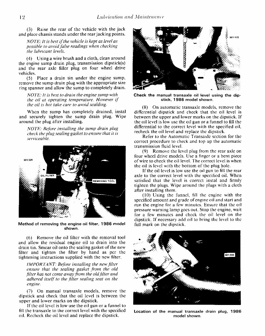
12 Lubrication and Alaintenance (3) Ralse the rear of the vehicle with the jack and place chassis stands under the rear jacking points. NOTE: It is best ifthe vehicle is kept as level as possible to avoidfalse readings when checking the lubricant levels. (4) Using a wire brush and a cloth, clean around the engine sump drain plug, transmission dipstick(s) and the rear axle filler plug on four wheel drive vehicles. (5) Place a drain tin under the engine sump, remove the sump drain plug with the appropriate size ring spanner and allow the sump to completely drain. NOTE: It is best to drain the engine sump with the oil at operating temperature. However if the oil is hot take care to avoid scalding. When the sump has completely drained, instal and securely tighten the sump drain plug. Wipe around the plug after installing. NOTE: Before installing the sump drain plug check the plug sealing gasket to ensure that it is serviceable. Method of removing the engine oil filter, 1986 model shown. (6) Remove the oil filter with the removal tool and allow the residual engine oil to drain into the drain tin. Smear oil onto the sealing gasket of the new filter and tighten the filter by hand as per the tightening instructions supplied with the new filter. IMPORTANT: Before installing the new filter ensure that the sealing gasket from the old filter has not come away from the oldfilter and adhered itself to the filter sealing seat on the engzne. (7) On manual transaxle models, remove the dipstick and check that the oil level is between the upper and lower marks on the dipstick. If the oil level is low use the oil gun or a funnel to fill the transaxle to the correct level with the specified oil. Recheck the oil level and replace the dipstick. Check the manual transaxle oil level using the dip- stick, 1986 model shown. (8) On automatic transaxle models, remove the differential dipstick and check that the oil level is between the upper and lower marks on the dipstick. If the oil level is low use the oil gun or a funnel to fill the differential to the correct level with the specified oil, recheck the oil level and replace the dipstick. Refer to the Automatic Transaxle section for the correct procedure to check and top up the automatic transmission fluid level. (9) Remove the level plug from the rear axle on four wheel drive models. Use a finger or a bent piece of wire to check the oil level. The correct level is when the oil is level with the bottom of the plug hole. If the oil level is low use the oil gun to fill the rear axle to the correct level with the specified oil. When satisfied that the level is correct instal and firmly tighten the plugs. Wipe around the plugs with a cloth after installing them. (10) Using the funnel, fill the engine with the specified amount and grade of engine oil and start and run the engine for a few minutes. Ensure that the oil pressure warning lamp goes out. Stop the engine, wait for a few minutes and check the oil level on the dipstick. If necessary add oil to bring the level to the full mark on the dipstick. Location of the manual transaxle drain plug, 1986 model shown.
This service and repair manual for the 1985-1996 Subaru BRAT provides thorough technical information for maintaining and repairing this compact utility vehicle. Covering all key systems, it includes detailed troubleshooting procedures, routine maintenance guidelines, torque specifications, and step-by-step instructions for mechanical and electrical repairs.
Designed to meet the needs of DIY enthusiasts and professional mechanics, the manual offers detailed wiring diagrams, factory specifications, and diagnostic procedures specific to the Subaru BRAT models produced from 1985 to 1996. Whether you’re working on the engine, drivetrain, suspension, or electrical systems, this manual ensures precise and reliable servicing.
Available in a digital format, this manual is accessible on computers or mobile devices, making it easy to use in a workshop or garage. Whether performing basic maintenance or more complex repairs, this service and repair manual is a critical resource for keeping your Subaru BRAT in top condition.
Printable: Yes Language: English Compatibility: Pretty much any electronic device, incl. PC & Mac computers, Android and Apple smartphones & tablet, etc. Requirements: Adobe Reader (free)