

CHANGED BY
EFFECTIVE DATE
AFFECTED VIN
GENERAL INFORMATION
DI ENG SM - 2004.4
GENERAL INFORMATION
00 SECTION DI0A
Table of Contents
CLEANNESS ....................................... DI0A-3
STRUCTURE ...................................... DI0A-8
ENGINE CONTROLS ....................... DI0A-11
ECU related components .............. DI0A-11
Engine and sensors ..................... DI0A-12
Electrical components and
pre heating system ...................... DI0A-13
INTAKE SYSTEM ............................. DI0A-14
Intake air flow chart ...................... DI0A-15
INTAKE SYSTEM ............................. DI0A-16
Exhaust air flow chart ................... DI0A-17
LUBRICATION SYSTEM .................. DI0A-18
COOLING SYSTEM ......................... DI0A-19
Coolant flow chart ........................ DI0A-20
FUEL SYSTEM ................................. DI0A-21
Fuel supply system ...................... DI0A-22
GENERAL SPECIFICATIONS ........... DI0A-23
Vehicle specifications ................... DI0A-23
Maintenance ................................ DI0A-26
VEHICLE IDENTIFICATION .............. DI0A-28
HOW TO USE AND MAINTAIN WORKSHOP
MANUAL ........................................... DI0A-30
Consists of workshop manual ...... DI0A-30
Manual description ...................... DI0A-30
Guidelines for service work
safety ........................................... DI0A-31
Lifting points ................................. DI0A-36
Tightening torque of standard
bolts .............................................. DI0A-37
DI0A-3
CHANGED BY
EFFECTIVE DATE
AFFECTED VIN
GENERAL INFORMATION
DI ENG SM - 2004.4
The fuel system for DI engine consists of transfer (low pressure) line and high pressure line. Its highest pressure
reaches over 1600 bar. Some components in injector and HP pump are machined at the micrometer 100 µm of
preciseness. The pressure regulation and injector operation are done by electric source from engine ECU.
Accordingly, if the internal valve is stucked due to foreign materials, injector remains open. Even in this case, the
HP pump still operates to supply high pressurized fuel. This increases the pressure to combustion chamber (over
250 bar) and may cause fatal damage to engine.
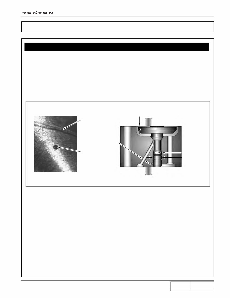
You can compare the thickness of injector nozzle hole and hair as shown in below figure (left side). The right side
figure shows the clearance between internal operating elements.
Cleanness of DI Engine Fuel System and Service Procedures
The core elements of fuel system has very high preciseness that is easily affected by dust or very small foreign
material. Therefore, make sure to keep the preliminary works and job procedures in next pages. If not, lots of
system problems and claims may arise.
CLEANNESS
Y220_0A035
Hair
Nozzle hole
Valve actuator lift: 0.028 mm
Diameter: 0.40 mm
Operating
clearance:
0.002 mm
Diameter:
2.0 mm
DI0A-4
CHANGED BY
EFFECTIVE DATE
AFFECTED VIN
GENERAL INFORMATION
DI ENG SM - 2004.4
1. Always keep the workshop and lift clean (especially, from dust).
2. Always keep the tools clean (from oil or foreign materials).
3. Wear a clean vinyl apron to prevent the fuzz, dust and foreign materials from getting into fuel system. Wash
your hands and do not wear working gloves.
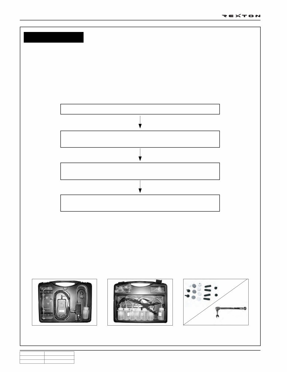
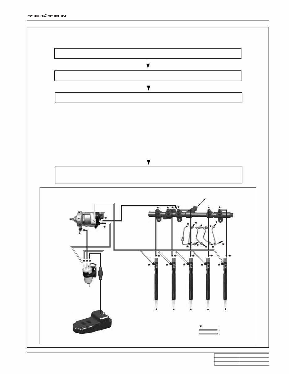
4. Follow the below procedures before starting service works for fuel system.
Job procedures
Carefully listen the symptoms and problems from customer.
Visually check the leaks and vehicle appearance on the wiring harnesses
and connectors in engine compartment.
Perform the diagnosis proceee with Scan-i
(refer to “DIAGNOSIS” section in this manual).
Locate the fault. If the cause is from fuel system (from priming pump to
injector, including return line), follow the step 1 through step 3 above.
5. If the problem is from HP pump, fuel supply line or injector, prepare the clean special tools and sealing caps
to perform the diagnosis for DI engine fuel system in “DIAGNOSIS” section in this manual. At this point,
thoroughly clean the related area in engine compartment.
Notice
Clean the engine compartment before starting service works.
Tool kit for high pressure line Took kit for low pressure line Removal tool box and cap kits
DI0A-5
CHANGED BY
EFFECTIVE DATE
AFFECTED VIN
GENERAL INFORMATION
DI ENG SM - 2004.4
6. Follow the job procedures. If you find a defective component, replace it with new one.
Y220_0A039
Fuel pressure sensor
Common rail
Injection
pipe
Injector
High pressure pump
IMV valve
Transfer pump and high
pressure pump
Fuel temperature sensor
Fuel tank
Fuel filter
Priming
pump
Water separator
Water detection sensor
Disconnect the negative battery cable.
Plug the disconnected parts with sealing caps, and remove the caps immediately
before replacing the components.
Once disconnected, the fuel pipes between HP pump and fuel rail and between fuel rail
and each injector should be replaced with new ones. The pipes should be tightened to
specified tightening torques during installation. Over or under torques out of specified
range may cause damages and leaks at connections. Once installed, the pipes have been
deformed according to the force during installtion, therefore they are not reusable.
The copper washer on injector should be replaced with new one. The injector holder bolt
should be tightened to specified tightening torque as well. If not, the injection point may be
deviated from correct position, and it may cause engine disorder.
Supply line
Return line
Cap position
Use special tools and torque wrench to perform the correct works.
For safety reasons: check pressure is low before opening the HP systems (pipes)
DI0A-6
CHANGED BY
EFFECTIVE DATE
AFFECTED VIN
GENERAL INFORMATION
DI ENG SM - 2004.4
7. Plug the removed components with clean and
undamaged sealing caps and store it into the box to
keep the conditions when it was installed.
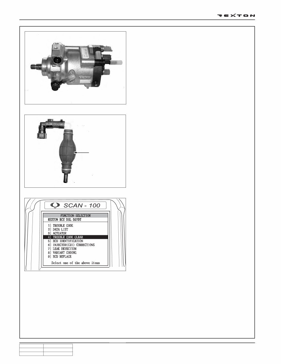
8. Clear the high pressure offset value by Scan-100 after
replacing the high pressure pump.
9. To supply the fuel to transfer line of HP pump press
the priming pump until it becomes hard.
10. Check the installed components again and connect
the negative battery cable. Start the engine and check
the operating status.
11. With Scan-i, check if there are current faults and erase
the history faults.
Note
For details, refer to “DI10 Diagnosis teable”.
Y220_0A040
Y220_0A041
Y220_0A042
Priming pump
Warning
Do not crank engine before having filled pump.
DI0A-7
CHANGED BY
EFFECTIVE DATE
AFFECTED VIN
GENERAL INFORMATION
DI ENG SM - 2004.4
SYSTEM SUPPLEMENT AND REMEDY AGAINST WATER IN FUEL
As mentioned above, some gas stations supply fuel with
excessive than specified water. In the conventional IDI
engine, excessive water in the fuel only causes dropping
engine power or engine hunting. However, fuel system in
the DI engine consists of precise components so water in
the fuel can cause malfunctions of HP pump due to poor
lubrication of pump caused by poor coating film during high
speed pumping and bacterization (under long period parking).
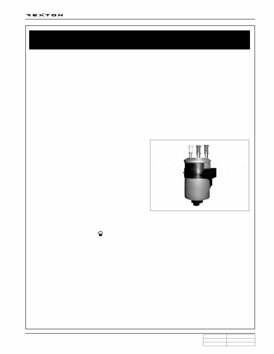
To prevent problems can be caused by excessive water in
fuel, water separator is installed inside of fuel filter. When
fuel is passing filter, water that has relatively bigger specific
gravity is accumulated on the bottom of the filter.
SYSTEM SUPPLEMENT AGAINST PARAFFIN SEPARATION.
In case of Diesel fuel, paraffin, one of the elements, can be separated from fuel during winter and then can stick on
the fuel filter blocking fuel flow and causing difficult starting finally. Oil companies supply summer fuel and winter
fuel by differentiating mixing ratio of kerosene and other elements by region and season. However, above phenomenon
can be happened if stations have poor facilities or sell improper fuel for the season.
In case of DI engine, purity of fuel is very important factor to keep internal preciseness of HP pump and injector.
Accordingly, more dense mesh than conventional fuel filter is used. To prevent fuel filter internal clogging due to
paraffin separation, SYMC is using fuel line that high pressure and temperature fuel injected by injector returns
through fuel filter to have an effect of built-in heater (see fuel system).
DI Engine and Its Expected Problems and Remedies Can be Caused
by Water in Fuel
Y220_0A041
If water in the separator on the fuel filter exceeds a certain level, it will be supplied to HP pump with fuel, so the
engine ECU turns on warning light ( ) on the meter cluster and buzzer if water level is higher than a certain level.
Due to engine layout, a customer cannot easily drain water from fuel filter directly, so if a customer checks in to
change engine oil, be sure to perform water drain from fuel filter. (See fuel system for details.)
DI0A-8
CHANGED BY
EFFECTIVE DATE
AFFECTED VIN
GENERAL INFORMATION
DI ENG SM - 2004.4
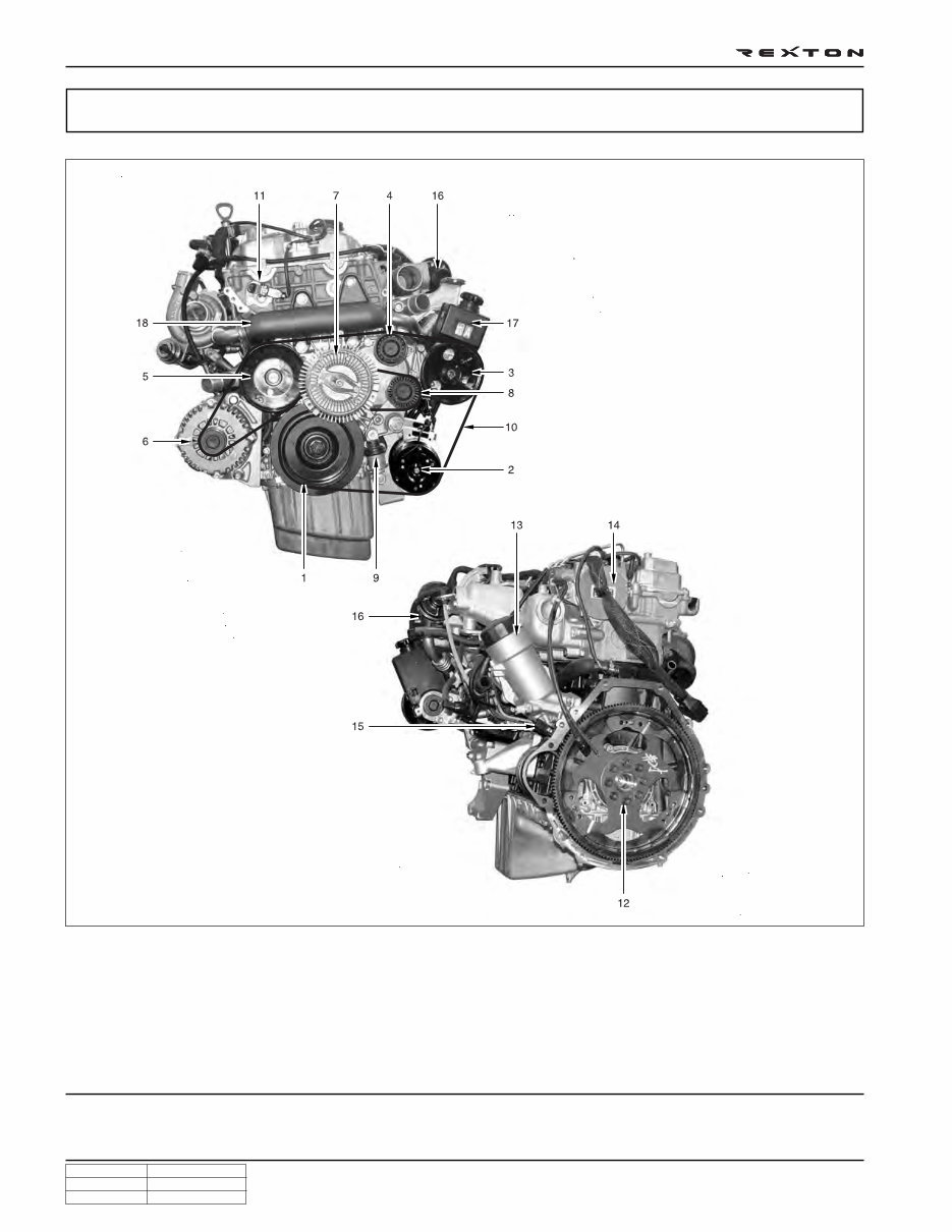
Front view
Rear view
Y220_0A001
STRUCTURE
1. TVD (Torsional Vibration Damper)
2. Air conditioner compressor
3. Power steering pump pulley
4. Idle pulley
5. Water pump pulley
6. Alternator
7. Cooling fan pulley & viscos clutch
8. Aut tensioner pulley
9. Auto tensioner
10. Poly-groove belt
11. Cam position sensor
12. Drive plate (M/T: DMF)
13. Oil filter housing
14. Vacuum pump
15. Crank position sensor
16. EGR valve
17. Power steering pump
18. EGR center pipe
DI0A-9
CHANGED BY
EFFECTIVE DATE
AFFECTED VIN
GENERAL INFORMATION
DI ENG SM - 2004.4
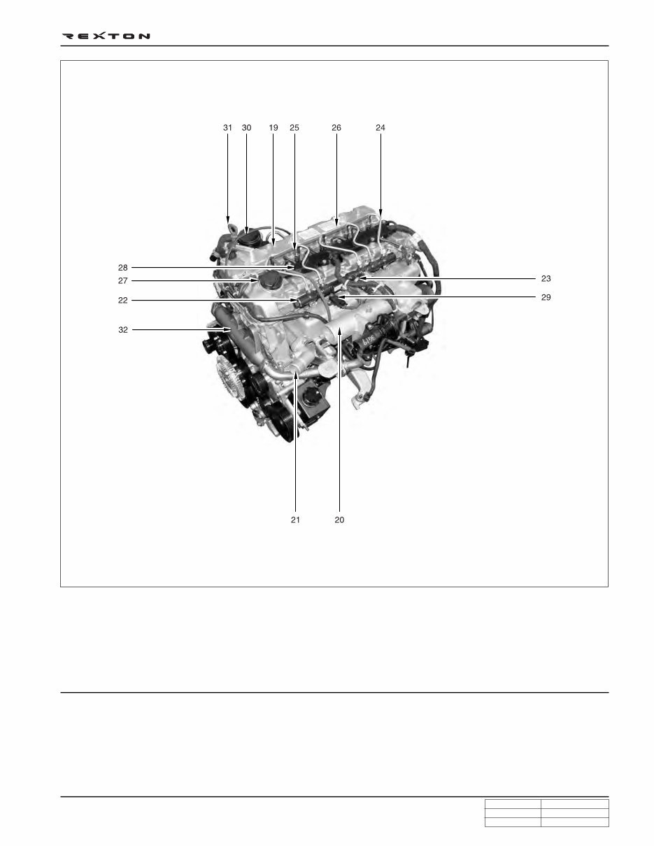
Top view
Y220_0A002
19. Cylinder head cover
20. Intake manifold
21. Water outlet port
22. Common rail
23. Fuel pressure sensor
24. Fuel pipe
25. Injector
26. Fuel return line
27. Oil filler cap
28. Glow plug
29. Booster pressure sensor
30. Oil separator
31. Oil dipstic
32. EGR center pipe
DI0A-10
CHANGED BY
EFFECTIVE DATE
AFFECTED VIN
GENERAL INFORMATION
DI ENG SM - 2004.4
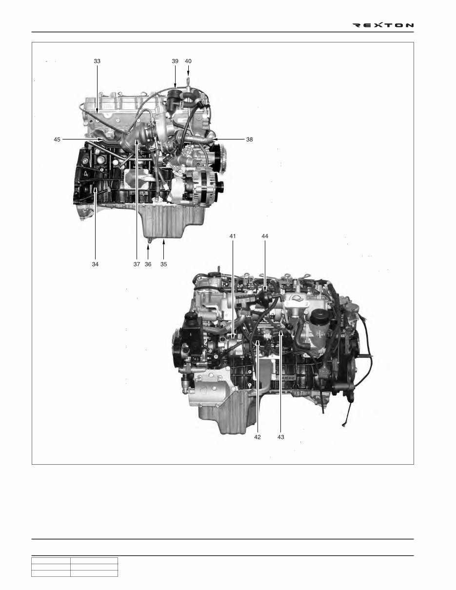
Right side view
Left side view
Y220_0A003
33. Cylinder head
34. Cylinder block
35. Oil pan
36. Drain plug
37. Turbocharger
38. EGR - RH pipe
39. Oil separator
40. Oil dipstic
41. HP pump
42. Turbocharger vacuum modulator
43. EGR valve vacuum modulator
44. EGR valve
45. Exhaust manifold
DI0A-11
CHANGED BY
EFFECTIVE DATE
AFFECTED VIN
GENERAL INFORMATION
DI ENG SM - 2004.4
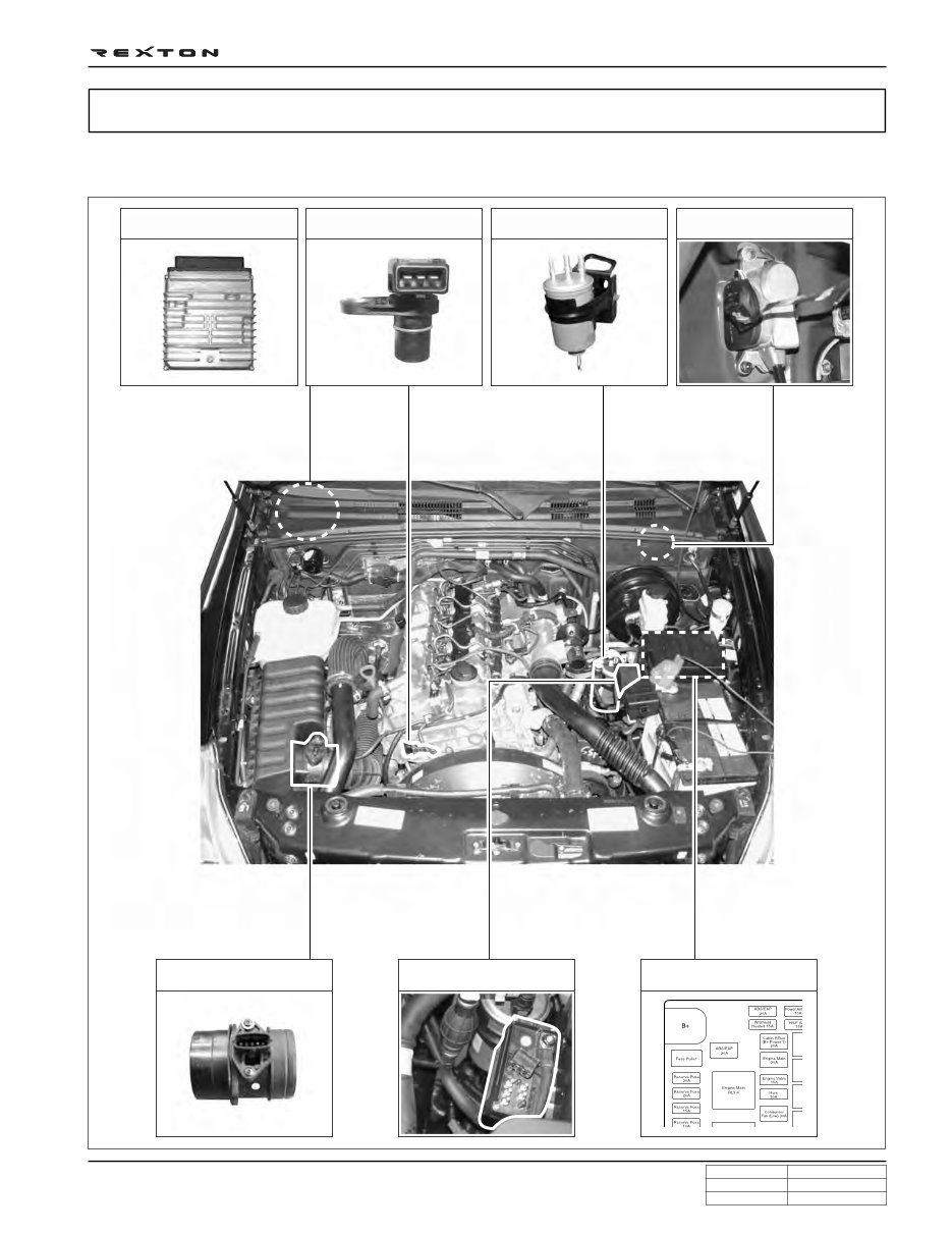
HFM sensor/intake air
temperature sensor
Pre heating time relay Main relay
ECU/barometric sensor Cam position sensor
Fuel filter
(water detection sensor)
Accelerator pedal sensor
ECU RELATED COMPONENTS
ENGINE CONTROLS
Y220_0A004
You're Reading a Preview
What's Included?
 Lifetime Access
Fast Download Speeds
Online & Offline Access
Access PDF Contents & Bookmarks
Full Search Facility
Print one or all pages of your manual
$35.99
2001-2006 SsangYong Rexton Service & Repair Manual
Viewed 13 Times Today

What's Included?
Lifetime Access
Fast Download Speeds
Online & Offline Access
Access PDF Contents & Bookmarks
Full Search Facility
Print one or all pages of your manual
$35.99

Secure transaction
What's Included?
Lifetime Access
Fast Download Speeds
Online & Offline Access
Access PDF Contents & Bookmarks
Full Search Facility
Print one or all pages of your manual
Description
- Complete service and repair manual for the SsangYong Rexton, covering production years 2001-2006, with all styles included.
- Contains detailed illustrations and step-by-step instructions, making it suitable for both professional mechanics and DIY enthusiasts.
- Printable format allows for easy access to the required information in the garage or workshop.
- Includes detailed sub-steps, notes, cautions, warnings, and numbered instructions for each repair procedure.
- Comprehensive troubleshooting and electrical service procedures combined with detailed wiring diagrams for ease of use.
- File format: .PDF (Windows & Mac & Linux).
- Total Pages: 2,000 pages.
- Product is instantly accessible without any restrictions.
Direct Preview Link: SsangYong Rexton 2001-2006 Preview


