

2012-2015 Skoda Octavia III Service & Repair Manual
What's Included?
Fast Download Speeds
Offline Viewing
Access Contents & Bookmarks
Full Search Facility
Print one or all pages of your manual
Workshop Manual
Octavia III 2013 ➤
Octavia III 2014 ➤
1.2/63; 77 kW TSI engine
Engine ID
CJZB CJZA
Edition 11.2014
Service
Service Department. Technical Information

List of Workshop Manual Repair GroupsList of Workshop Manual
Repair GroupsList of Workshop Manual Repair Groups
Repair Group
00 - Technical data
10 - Removing and installing engine
13 - Crankshaft group
15 - Cylinder head, valve gear
17 - Lubrication
19 - Cooling
20 - Fuel supply system
21 - Turbocharging/supercharging
24 - Mixture preparation - injection
26 - Exhaust system
28 - Ignition system
Service

Contents
00 - Technical data . . . . . . . . . . . . . . . . . . . . . . . . . . . . . . . . . . . . . . . . . . . . . . . . . . . . 1
1 Identification . . . . . . . . . . . . . . . . . . . . . . . . . . . . . . . . . . . . . . . . . . . . . . . . . . . . . . . . . . . . 1
1.1 Engine number, engine data . . . . . . . . . . . . . . . . . . . . . . . . . . . . . . . . . . . . . . . . . . . . . . . . 1
2 Safety instructions . . . . . . . . . . . . . . . . . . . . . . . . . . . . . . . . . . . . . . . . . . . . . . . . . . . . . . . . 2
2.1 Safety precautions when working on fuel supply system . . . . . . . . . . . . . . . . . . . . . . . . . . 2
2.2 Safety measures for working on vehicles with start/stop system . . . . . . . . . . . . . . . . . . . . 3
2.3 Safety precautions during road tests in which testing and measuring equipment is used . . 4
2.4 Safety precautions when working on cooling system . . . . . . . . . . . . . . . . . . . . . . . . . . . . . . 4
2.5 Safety precautions when working on the injection system . . . . . . . . . . . . . . . . . . . . . . . . . . 5
2.6 Safety precautions when working on ignition system . . . . . . . . . . . . . . . . . . . . . . . . . . . . . . 6
3 Repair instructions . . . . . . . . . . . . . . . . . . . . . . . . . . . . . . . . . . . . . . . . . . . . . . . . . . . . . . . . 7
3.1 Rules of cleanliness . . . . . . . . . . . . . . . . . . . . . . . . . . . . . . . . . . . . . . . . . . . . . . . . . . . . . . 7
3.2 Foreign bodies in the engine . . . . . . . . . . . . . . . . . . . . . . . . . . . . . . . . . . . . . . . . . . . . . . . . 7
3.3 Contact corrosion . . . . . . . . . . . . . . . . . . . . . . . . . . . . . . . . . . . . . . . . . . . . . . . . . . . . . . . . 7
3.4 Cable routing and securing . . . . . . . . . . . . . . . . . . . . . . . . . . . . . . . . . . . . . . . . . . . . . . . . 8
3.5 Assembly of radiators and capacitors . . . . . . . . . . . . . . . . . . . . . . . . . . . . . . . . . . . . . . . . 8
3.6 Additional instructions when undertaking assembly work on the air-conditioning system . . 8
3.7 General instructions for charge air system . . . . . . . . . . . . . . . . . . . . . . . . . . . . . . . . . . . . . . 8
3.8 General notes on the ignition system . . . . . . . . . . . . . . . . . . . . . . . . . . . . . . . . . . . . . . . . . . 9
3.9 General notes on the injection system . . . . . . . . . . . . . . . . . . . . . . . . . . . . . . . . . . . . . . . . 9
3.10 Reduce pressure in the high-pressure system . . . . . . . . . . . . . . . . . . . . . . . . . . . . . . . . . . 10
10 - Removing and installing engine . . . . . . . . . . . . . . . . . . . . . . . . . . . . . . . . . . . . . . 11
1 Removing and installing engine . . . . . . . . . . . . . . . . . . . . . . . . . . . . . . . . . . . . . . . . . . . . . . 11
1.1 Removing engine . . . . . . . . . . . . . . . . . . . . . . . . . . . . . . . . . . . . . . . . . . . . . . . . . . . . . . . . 11
1.2 Securing the engine to the assembly stand . . . . . . . . . . . . . . . . . . . . . . . . . . . . . . . . . . . . 21
1.3 Installing engine . . . . . . . . . . . . . . . . . . . . . . . . . . . . . . . . . . . . . . . . . . . . . . . . . . . . . . . . . . 22
2 Assembly bracket . . . . . . . . . . . . . . . . . . . . . . . . . . . . . . . . . . . . . . . . . . . . . . . . . . . . . . . . 26
2.1 Unit mounting - summary of components . . . . . . . . . . . . . . . . . . . . . . . . . . . . . . . . . . . . . . 26
2.2 Removing and installing engine mount . . . . . . . . . . . . . . . . . . . . . . . . . . . . . . . . . . . . . . . . 28
2.3 Removing and installing gearbox mount . . . . . . . . . . . . . . . . . . . . . . . . . . . . . . . . . . . . . . 28
2.4 Check assembly bracket setting . . . . . . . . . . . . . . . . . . . . . . . . . . . . . . . . . . . . . . . . . . . . . . 31
2.5 Adjusting the assembly bracket . . . . . . . . . . . . . . . . . . . . . . . . . . . . . . . . . . . . . . . . . . . . . . 31
13 - Crankshaft group . . . . . . . . . . . . . . . . . . . . . . . . . . . . . . . . . . . . . . . . . . . . . . . . . . 34
1 Cylinder block (pulley end) . . . . . . . . . . . . . . . . . . . . . . . . . . . . . . . . . . . . . . . . . . . . . . . . . . 34
1.1 V-ribbed belt - Summary of components . . . . . . . . . . . . . . . . . . . . . . . . . . . . . . . . . . . . . . 34
1.2 Removing and installing poly V-belt . . . . . . . . . . . . . . . . . . . . . . . . . . . . . . . . . . . . . . . . . . 37
1.3 Removing and installing tensioning device for V-ribbed belt . . . . . . . . . . . . . . . . . . . . . . . . 39
1.4 Removing and installing ribbed belt pulley . . . . . . . . . . . . . . . . . . . . . . . . . . . . . . . . . . . . . . 40
1.5 Removing and installing engine support . . . . . . . . . . . . . . . . . . . . . . . . . . . . . . . . . . . . . . 41
1.6 Renewing crankshaft oil seal - belt pulley end . . . . . . . . . . . . . . . . . . . . . . . . . . . . . . . . . . 44
2 Cylinder block, gearbox end . . . . . . . . . . . . . . . . . . . . . . . . . . . . . . . . . . . . . . . . . . . . . . . . 47
2.1 Gearbox side cylinder block - Summary of components . . . . . . . . . . . . . . . . . . . . . . . . . . 47
2.2 Removing and installing flywheel . . . . . . . . . . . . . . . . . . . . . . . . . . . . . . . . . . . . . . . . . . . . 48
2.3 Removing and installing sealing flange on gearbox side . . . . . . . . . . . . . . . . . . . . . . . . . . 49
3 Crankshaft . . . . . . . . . . . . . . . . . . . . . . . . . . . . . . . . . . . . . . . . . . . . . . . . . . . . . . . . . . . . . . 57
3.1 Crankshaft mass . . . . . . . . . . . . . . . . . . . . . . . . . . . . . . . . . . . . . . . . . . . . . . . . . . . . . . . . 57
3.2 Measuring axial play of crankshaft . . . . . . . . . . . . . . . . . . . . . . . . . . . . . . . . . . . . . . . . . . . . 57
3.3 Replace needle bearing for crankshaft . . . . . . . . . . . . . . . . . . . . . . . . . . . . . . . . . . . . . . . . 57
4 Pistons and conrods . . . . . . . . . . . . . . . . . . . . . . . . . . . . . . . . . . . . . . . . . . . . . . . . . . . . . . 59
4.1 Assembly overview - piston and conrod . . . . . . . . . . . . . . . . . . . . . . . . . . . . . . . . . . . . . . . . 59
Octavia III 2013 ➤ , Octavia III 2014 ➤
1.2/63; 77 kW TSI engine - Edition 11.2014
Contents i

4.2 Separating new conrod . . . . . . . . . . . . . . . . . . . . . . . . . . . . . . . . . . . . . . . . . . . . . . . . . . . . 61
4.3 Removing and installing the piston . . . . . . . . . . . . . . . . . . . . . . . . . . . . . . . . . . . . . . . . . . . . 61
4.4 Checking piston and cylinder bore . . . . . . . . . . . . . . . . . . . . . . . . . . . . . . . . . . . . . . . . . . . . 63
4.5 Removing and installing oil injection nozzles . . . . . . . . . . . . . . . . . . . . . . . . . . . . . . . . . . . . 64
15 - Cylinder head, valve gear . . . . . . . . . . . . . . . . . . . . . . . . . . . . . . . . . . . . . . . . . . 66
1 Cylinder head . . . . . . . . . . . . . . . . . . . . . . . . . . . . . . . . . . . . . . . . . . . . . . . . . . . . . . . . . . . . 66
1.1 Summary of components - cylinder head . . . . . . . . . . . . . . . . . . . . . . . . . . . . . . . . . . . . . . 66
1.2 Summary of components - camshaft housing . . . . . . . . . . . . . . . . . . . . . . . . . . . . . . . . . . 68
1.3 Removing and installing cylinder head . . . . . . . . . . . . . . . . . . . . . . . . . . . . . . . . . . . . . . . . 69
1.4 Removing and installing camshaft housing . . . . . . . . . . . . . . . . . . . . . . . . . . . . . . . . . . . . 73
1.5 Checking compression . . . . . . . . . . . . . . . . . . . . . . . . . . . . . . . . . . . . . . . . . . . . . . . . . . . . 77
2 Toothed belt drive . . . . . . . . . . . . . . . . . . . . . . . . . . . . . . . . . . . . . . . . . . . . . . . . . . . . . . . . 79
2.1 Summary of components - toothed belt guard . . . . . . . . . . . . . . . . . . . . . . . . . . . . . . . . . . 79
2.2 Summary of components - toothed belt . . . . . . . . . . . . . . . . . . . . . . . . . . . . . . . . . . . . . . . . 80
2.3 Checking valve timing . . . . . . . . . . . . . . . . . . . . . . . . . . . . . . . . . . . . . . . . . . . . . . . . . . . . 81
2.4 Remove the toothed belt from the camshaft . . . . . . . . . . . . . . . . . . . . . . . . . . . . . . . . . . . . 86
2.5 Removing and installing toothed belt . . . . . . . . . . . . . . . . . . . . . . . . . . . . . . . . . . . . . . . . . . 99
3 Valve gear . . . . . . . . . . . . . . . . . . . . . . . . . . . . . . . . . . . . . . . . . . . . . . . . . . . . . . . . . . . . . . 113
3.1 Assembly overview - valve gear . . . . . . . . . . . . . . . . . . . . . . . . . . . . . . . . . . . . . . . . . . . . . . 113
3.2 Measuring axial play of camshaft . . . . . . . . . . . . . . . . . . . . . . . . . . . . . . . . . . . . . . . . . . . . 114
3.3 Removing and installing camshaft control . . . . . . . . . . . . . . . . . . . . . . . . . . . . . . . . . . . . . . 114
3.4 Removing and installing camshaft oil seal . . . . . . . . . . . . . . . . . . . . . . . . . . . . . . . . . . . . . . 115
3.5 Removing and installing N205 the camshaft adjustment valve 1 . . . . . . . . . . . . . . . . . . . . 119
3.6 Removing and installing valve stem seal . . . . . . . . . . . . . . . . . . . . . . . . . . . . . . . . . . . . . . 119
4 Inlet and exhaust valves . . . . . . . . . . . . . . . . . . . . . . . . . . . . . . . . . . . . . . . . . . . . . . . . . . . . 125
4.1 Checking valve guides . . . . . . . . . . . . . . . . . . . . . . . . . . . . . . . . . . . . . . . . . . . . . . . . . . . . 125
4.2 Testing valves . . . . . . . . . . . . . . . . . . . . . . . . . . . . . . . . . . . . . . . . . . . . . . . . . . . . . . . . . . 125
4.3 Valve dimensions . . . . . . . . . . . . . . . . . . . . . . . . . . . . . . . . . . . . . . . . . . . . . . . . . . . . . . . . 125
17 - Lubrication . . . . . . . . . . . . . . . . . . . . . . . . . . . . . . . . . . . . . . . . . . . . . . . . . . . . . . 126
1 Lubrication system . . . . . . . . . . . . . . . . . . . . . . . . . . . . . . . . . . . . . . . . . . . . . . . . . . . . . . . . 126
1.1 Oil sump and oil pump - Summary of components . . . . . . . . . . . . . . . . . . . . . . . . . . . . . . 126
1.2 Removing and installing oil sump . . . . . . . . . . . . . . . . . . . . . . . . . . . . . . . . . . . . . . . . . . . . 128
1.3 Removing and installing oil pump . . . . . . . . . . . . . . . . . . . . . . . . . . . . . . . . . . . . . . . . . . . . 131
1.4 Removing and installing oil level and oil temperature sender G266 . . . . . . . . . . . . . . . . . . 134
2 Engine oil cooler . . . . . . . . . . . . . . . . . . . . . . . . . . . . . . . . . . . . . . . . . . . . . . . . . . . . . . . . . . 135
2.1 Summary of components - engine oil cooler . . . . . . . . . . . . . . . . . . . . . . . . . . . . . . . . . . . . 135
2.2 Removing and installing engine oil cooler . . . . . . . . . . . . . . . . . . . . . . . . . . . . . . . . . . . . . . 135
3 Crankcase ventilation . . . . . . . . . . . . . . . . . . . . . . . . . . . . . . . . . . . . . . . . . . . . . . . . . . . . . . 137
3.1 Summary of components - crankcase ventilation . . . . . . . . . . . . . . . . . . . . . . . . . . . . . . . . 137
3.2 Removing and installing oil separator . . . . . . . . . . . . . . . . . . . . . . . . . . . . . . . . . . . . . . . . 137
4 Oil filter, oil pressure switch . . . . . . . . . . . . . . . . . . . . . . . . . . . . . . . . . . . . . . . . . . . . . . . . 141
4.1 Summary of components - oil filter/oil pressure switch . . . . . . . . . . . . . . . . . . . . . . . . . . . . 141
4.2 Removing and installing oil pressure switch for reduced oil pressure F378 . . . . . . . . . . . . 141
4.3 Checking oil pressure and oil pressure switch . . . . . . . . . . . . . . . . . . . . . . . . . . . . . . . . . . 142
4.4 Removing and installing oil filter housing . . . . . . . . . . . . . . . . . . . . . . . . . . . . . . . . . . . . . . 143
19 - Cooling . . . . . . . . . . . . . . . . . . . . . . . . . . . . . . . . . . . . . . . . . . . . . . . . . . . . . . . . . . 144
1 Cooling system, coolant . . . . . . . . . . . . . . . . . . . . . . . . . . . . . . . . . . . . . . . . . . . . . . . . . . . . 144
1.1 Coolant hose schematic diagram . . . . . . . . . . . . . . . . . . . . . . . . . . . . . . . . . . . . . . . . . . . . 144
1.2 Draining and filling coolant . . . . . . . . . . . . . . . . . . . . . . . . . . . . . . . . . . . . . . . . . . . . . . . . . . 147
1.3 Checking cooling system for leaks . . . . . . . . . . . . . . . . . . . . . . . . . . . . . . . . . . . . . . . . . . . . 151
2 Coolant pump, regulation of cooling system . . . . . . . . . . . . . . . . . . . . . . . . . . . . . . . . . . . . 154
2.1 Summary of components - coolant pump/coolant thermostat . . . . . . . . . . . . . . . . . . . . . . 154
Octavia III 2013 ➤ , Octavia III 2014 ➤
1.2/63; 77 kW TSI engine - Edition 11.2014
ii Contents

2.2 Summary of components - electric coolant pump . . . . . . . . . . . . . . . . . . . . . . . . . . . . . . . . 157
2.3 Summary of components - coolant temperature sender . . . . . . . . . . . . . . . . . . . . . . . . . . 158
2.4 Removing and installing coolant pump . . . . . . . . . . . . . . . . . . . . . . . . . . . . . . . . . . . . . . . . 158
2.5 Removing and installing toothed belt pulley for coolant pump . . . . . . . . . . . . . . . . . . . . . . 162
2.6 Removing and installing electric coolant pump . . . . . . . . . . . . . . . . . . . . . . . . . . . . . . . . . . 163
2.7 Removing and installing thermostat . . . . . . . . . . . . . . . . . . . . . . . . . . . . . . . . . . . . . . . . . . 164
2.8 Removing and installing coolant temperature sender G62 . . . . . . . . . . . . . . . . . . . . . . . . 167
2.9 Removing and installing coolant temperature sender at radiator outlet G83 . . . . . . . . . . 168
3 Parts of cooling system engine side . . . . . . . . . . . . . . . . . . . . . . . . . . . . . . . . . . . . . . . . . . 170
3.1 Summary of components . . . . . . . . . . . . . . . . . . . . . . . . . . . . . . . . . . . . . . . . . . . . . . . . . . 170
3.2 Removing and installing coolant pipe . . . . . . . . . . . . . . . . . . . . . . . . . . . . . . . . . . . . . . . . . . 170
4 Radiator and radiator fan . . . . . . . . . . . . . . . . . . . . . . . . . . . . . . . . . . . . . . . . . . . . . . . . . . 173
4.1 Radiator version 1 - Summary of components . . . . . . . . . . . . . . . . . . . . . . . . . . . . . . . . . . 173
4.2 Radiator version 2 - Summary of components . . . . . . . . . . . . . . . . . . . . . . . . . . . . . . . . . . 175
4.3 Radiator version 3 - Summary of components . . . . . . . . . . . . . . . . . . . . . . . . . . . . . . . . . . 176
4.4 Fan shroud with a radiator fan - Summary of components . . . . . . . . . . . . . . . . . . . . . . . . 178
4.5 Fan shroud with two radiator fans - Summary of components . . . . . . . . . . . . . . . . . . . . . . 179
4.6 Removing and installing radiator . . . . . . . . . . . . . . . . . . . . . . . . . . . . . . . . . . . . . . . . . . . . 179
4.7 Removing and installing fan shroud for radiator fan . . . . . . . . . . . . . . . . . . . . . . . . . . . . . . 182
4.8 Removing and installing radiator fan V7 . . . . . . . . . . . . . . . . . . . . . . . . . . . . . . . . . . . . . . 184
4.9 Removing and installing radiator fan 2 V177 . . . . . . . . . . . . . . . . . . . . . . . . . . . . . . . . . . . . 185
20 - Fuel supply system . . . . . . . . . . . . . . . . . . . . . . . . . . . . . . . . . . . . . . . . . . . . . . . . 186
1 Fuel tank and fuel delivery unit . . . . . . . . . . . . . . . . . . . . . . . . . . . . . . . . . . . . . . . . . . . . . . 186
1.1 Fuel tank - Summary of components . . . . . . . . . . . . . . . . . . . . . . . . . . . . . . . . . . . . . . . . . . 186
1.2 Extract fuel from the fuel tank . . . . . . . . . . . . . . . . . . . . . . . . . . . . . . . . . . . . . . . . . . . . . . . . 189
1.3 Removing and installing the fuel tank . . . . . . . . . . . . . . . . . . . . . . . . . . . . . . . . . . . . . . . . . . 195
1.4 Summary of components - fuel delivery unit and sender for fuel gauge display . . . . . . . . 200
1.5 Fuel delivery unit with sender for fuel gauge display . . . . . . . . . . . . . . . . . . . . . . . . . . . . . . 201
1.6 Removing and installing the sender for fuel gauge display G . . . . . . . . . . . . . . . . . . . . . . 204
1.7 Checking fuel pump . . . . . . . . . . . . . . . . . . . . . . . . . . . . . . . . . . . . . . . . . . . . . . . . . . . . . . 205
1.8 Removing and installing fuel pump control unit J538 . . . . . . . . . . . . . . . . . . . . . . . . . . . . 210
2 Separating push-on couplings . . . . . . . . . . . . . . . . . . . . . . . . . . . . . . . . . . . . . . . . . . . . . . 211
3 Accelerator pedal . . . . . . . . . . . . . . . . . . . . . . . . . . . . . . . . . . . . . . . . . . . . . . . . . . . . . . . . 215
3.1 Assembly overview - accelerator module . . . . . . . . . . . . . . . . . . . . . . . . . . . . . . . . . . . . . . 215
3.2 Removing and installing accelerator module . . . . . . . . . . . . . . . . . . . . . . . . . . . . . . . . . . . . 216
3.3 Disconnect connector for accelerator pedal module and fit on . . . . . . . . . . . . . . . . . . . . . . 216
4 Activated charcoal filter system . . . . . . . . . . . . . . . . . . . . . . . . . . . . . . . . . . . . . . . . . . . . . . 218
4.1 Assembly overview - activated charcoal filter system . . . . . . . . . . . . . . . . . . . . . . . . . . . . 218
4.2 Removing and installing activated charcoal filter . . . . . . . . . . . . . . . . . . . . . . . . . . . . . . . . 218
4.3 Checking the fuel tank venting . . . . . . . . . . . . . . . . . . . . . . . . . . . . . . . . . . . . . . . . . . . . . . 219
21 - Turbocharging/supercharging . . . . . . . . . . . . . . . . . . . . . . . . . . . . . . . . . . . . . . . . 221
1 Exhaust gas turbocharger . . . . . . . . . . . . . . . . . . . . . . . . . . . . . . . . . . . . . . . . . . . . . . . . . . 221
1.1 Summary of components - exhaust gas turbocharger . . . . . . . . . . . . . . . . . . . . . . . . . . . . 221
1.2 Removing and installing exhaust gas turbocharger . . . . . . . . . . . . . . . . . . . . . . . . . . . . . . 223
1.3 Removing and installing charge pressure regulator V465 . . . . . . . . . . . . . . . . . . . . . . . . . . 227
2 Charge-air system . . . . . . . . . . . . . . . . . . . . . . . . . . . . . . . . . . . . . . . . . . . . . . . . . . . . . . . . 228
2.1 Summary of components - charge air system . . . . . . . . . . . . . . . . . . . . . . . . . . . . . . . . . . 228
2.2 Removing and installing charge pressure sender GX26 . . . . . . . . . . . . . . . . . . . . . . . . . . 229
2.3 Removing and installing charge air cooler . . . . . . . . . . . . . . . . . . . . . . . . . . . . . . . . . . . . . . 230
2.4 Checking the charge-air system for leak tightness . . . . . . . . . . . . . . . . . . . . . . . . . . . . . . . . 232
24 - Mixture preparation - injection . . . . . . . . . . . . . . . . . . . . . . . . . . . . . . . . . . . . . . . . 234
1 Injection system . . . . . . . . . . . . . . . . . . . . . . . . . . . . . . . . . . . . . . . . . . . . . . . . . . . . . . . . . . 234
Octavia III 2013 ➤ , Octavia III 2014 ➤
1.2/63; 77 kW TSI engine - Edition 11.2014
Contents iii

1.1 Injection system - Fitting location of the injection system . . . . . . . . . . . . . . . . . . . . . . . . . . 234
2 Air filter . . . . . . . . . . . . . . . . . . . . . . . . . . . . . . . . . . . . . . . . . . . . . . . . . . . . . . . . . . . . . . . . 238
2.1 Assembly overview - air filter housing . . . . . . . . . . . . . . . . . . . . . . . . . . . . . . . . . . . . . . . . 238
2.2 Removing and installing air filter housing . . . . . . . . . . . . . . . . . . . . . . . . . . . . . . . . . . . . . . 239
3 Intake manifold . . . . . . . . . . . . . . . . . . . . . . . . . . . . . . . . . . . . . . . . . . . . . . . . . . . . . . . . . . 240
3.1 Assembly overview - intake manifold . . . . . . . . . . . . . . . . . . . . . . . . . . . . . . . . . . . . . . . . . . 240
3.2 Removing and installing intake manifold . . . . . . . . . . . . . . . . . . . . . . . . . . . . . . . . . . . . . . 241
3.3 Removing and installing the throttle valve control unit GX3 . . . . . . . . . . . . . . . . . . . . . . . . 244
3.4 Clean throttle valve control unit GX3 . . . . . . . . . . . . . . . . . . . . . . . . . . . . . . . . . . . . . . . . . . 246
4 Injectors . . . . . . . . . . . . . . . . . . . . . . . . . . . . . . . . . . . . . . . . . . . . . . . . . . . . . . . . . . . . . . . . 248
4.1 Assembly overview - fuel rail with injectors . . . . . . . . . . . . . . . . . . . . . . . . . . . . . . . . . . . . 248
4.2 Removing and installing the fuel distributor . . . . . . . . . . . . . . . . . . . . . . . . . . . . . . . . . . . . 249
4.3 Removing and installing injectors . . . . . . . . . . . . . . . . . . . . . . . . . . . . . . . . . . . . . . . . . . . . 250
4.4 Clean injection valves . . . . . . . . . . . . . . . . . . . . . . . . . . . . . . . . . . . . . . . . . . . . . . . . . . . . . . 255
5 Senders and sensors . . . . . . . . . . . . . . . . . . . . . . . . . . . . . . . . . . . . . . . . . . . . . . . . . . . . . . 257
5.1 Removing and installing intake manifold pressure sender GX9 . . . . . . . . . . . . . . . . . . . . 257
5.2 Removing and installing fuel pressure sender G247 . . . . . . . . . . . . . . . . . . . . . . . . . . . . . . 257
5.3 Check fuel pressure sender G247 . . . . . . . . . . . . . . . . . . . . . . . . . . . . . . . . . . . . . . . . . . . . 258
6 High pressure pump . . . . . . . . . . . . . . . . . . . . . . . . . . . . . . . . . . . . . . . . . . . . . . . . . . . . . . 261
6.1 Summary of components - high pressure pump . . . . . . . . . . . . . . . . . . . . . . . . . . . . . . . . 261
6.2 Removing and installing the high pressure pump . . . . . . . . . . . . . . . . . . . . . . . . . . . . . . . . 262
6.3 Removing and installing high pressure pipe . . . . . . . . . . . . . . . . . . . . . . . . . . . . . . . . . . . . 263
7 Lambda probe . . . . . . . . . . . . . . . . . . . . . . . . . . . . . . . . . . . . . . . . . . . . . . . . . . . . . . . . . . 265
7.1 Summary of components - lambda probe . . . . . . . . . . . . . . . . . . . . . . . . . . . . . . . . . . . . . . 265
7.2 Removing and installing lambda probe GX10 / GX7 . . . . . . . . . . . . . . . . . . . . . . . . . . . . . . 266
8 Engine control unit . . . . . . . . . . . . . . . . . . . . . . . . . . . . . . . . . . . . . . . . . . . . . . . . . . . . . . . . 268
8.1 Removing and installing engine control unit J623 without protective housing . . . . . . . . . . 268
8.2 Removing and installing engine control unit J623 , engine control unit with protective
housing . . . . . . . . . . . . . . . . . . . . . . . . . . . . . . . . . . . . . . . . . . . . . . . . . . . . . . . . . . . . . . . . 268
26 - Exhaust system . . . . . . . . . . . . . . . . . . . . . . . . . . . . . . . . . . . . . . . . . . . . . . . . . . 272
1 Removing and installing exhaust system . . . . . . . . . . . . . . . . . . . . . . . . . . . . . . . . . . . . . . 272
1.1 Catalytic converter and component parts - Summary of components . . . . . . . . . . . . . . . . 272
1.2 Middle and rear silencer - Summary of components . . . . . . . . . . . . . . . . . . . . . . . . . . . . . . 274
1.3 Removing and installing catalytic converter with pre-exhaust pipe . . . . . . . . . . . . . . . . . . 275
1.4 Removing and installing or replacing the middle and rear silencer . . . . . . . . . . . . . . . . . . 277
1.5 Aligning exhaust system free of stress . . . . . . . . . . . . . . . . . . . . . . . . . . . . . . . . . . . . . . . . 279
1.6 Align exhaust tailpipe . . . . . . . . . . . . . . . . . . . . . . . . . . . . . . . . . . . . . . . . . . . . . . . . . . . . . . 279
1.7 Inspecting the exhaust system for leak tightness . . . . . . . . . . . . . . . . . . . . . . . . . . . . . . . . 280
28 - Ignition system . . . . . . . . . . . . . . . . . . . . . . . . . . . . . . . . . . . . . . . . . . . . . . . . . . . . 281
1 Ignition system . . . . . . . . . . . . . . . . . . . . . . . . . . . . . . . . . . . . . . . . . . . . . . . . . . . . . . . . . . 281
1.1 Assembly overview - ignition system . . . . . . . . . . . . . . . . . . . . . . . . . . . . . . . . . . . . . . . . . . 281
1.2 Removing and installing ignition coils with output stage . . . . . . . . . . . . . . . . . . . . . . . . . . 282
1.3 Removing and installing knock sensor 1 G61 . . . . . . . . . . . . . . . . . . . . . . . . . . . . . . . . . . 283
1.4 Removing and installing Hall sender G40 . . . . . . . . . . . . . . . . . . . . . . . . . . . . . . . . . . . . . . 284
1.5 Removing and installing engine speed sender G28 . . . . . . . . . . . . . . . . . . . . . . . . . . . . . . 284
Octavia III 2013 ➤ , Octavia III 2014 ➤
1.2/63; 77 kW TSI engine - Edition 11.2014
iv Contents
00 – Technical data
1 Identification
(SRL000738; Edition 11.2014)
⇒ “1.1 Engine number, engine data”, page 1
1.1 Engine number, engine data
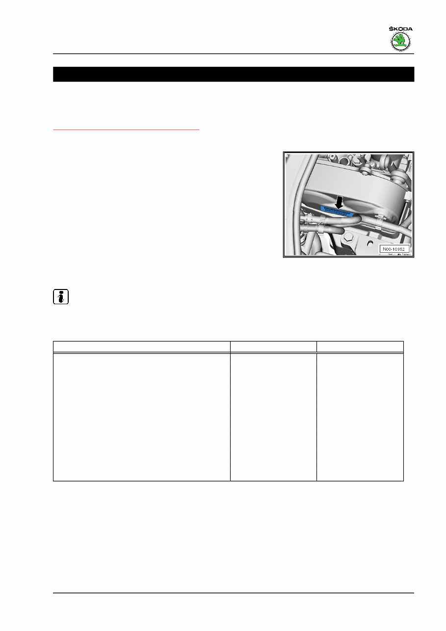
“The engine identification characters” and the “serial number” are
located on the sticker -arrow- at the top timing belt guard.
The “engine identification characters” and “serial numbers” are
also indicated on the engine above the engine connection with
the gearbox, on the vehicle data sticker and on the engine control
unit.
♦ Starting with the letter “C”, new four digit engine codes have
been introduced.
♦ The first 3 digits of the engine identification characters refer to
the displacement and the mechanical construction of the en‐
gine. They are type-punched on the cylinder block including
the serial number.
♦ The 4th digit refers to the output and torque of the engine and
depends upon the engine - J623- control unit.
Note
Fitting locations of vehicle data sticker ⇒ Maintenance ; Booklet
Octavia III .
Engine codes CJZA CJZB
Manufactured 01.2013 ► 11.2012 ►
Emission standards EU5 EU5
Capacity
cm
3
1197 1197
Output kW at rpm 77/4500-5500 63/4300-5300
Torque Nm at rpm 175/1400-4000 160/1400-3500
Bore ∅ mm 71.0 71.0
Stroke mm 75.6 75.6
Compression ratio 10.5 10.5
Cylinder/valves per cylinder 4 / 4 4 / 4
RON min. 95 unleaded 95 unleaded
Ignition system, fuel injection Motronic MED17 Motronic MED17
Firing order 1-3-4-2 1-3-4-2
Octavia III 2013 ➤ , Octavia III 2014 ➤
1.2/63; 77 kW TSI engine - Edition 11.2014
1. Identification 1
2 Safety instructions
⇒ “2.1 Safety precautions when working on fuel supply system”,
page 2
⇒ “2.2 Safety measures for working on vehicles with start/stop
system”, page 3
⇒ “2.3 Safety precautions during road tests in which testing and
measuring equipment is used”, page 4
⇒ “2.4 Safety precautions when working on cooling system”, page
4
⇒ “2.5 Safety precautions when working on the injection system”,
page 5
⇒ “2.6 Safety precautions when working on ignition system”, page
6
2.1 Safety precautions when working on
fuel supply system
WARNING
Fuel under high pressure creates a risk of injury.
Leaking fuel creates a fire hazard.
♦ The fuel system is under pressure! Before opening the
high-pressure system, the fuel pressure must be reduced
to residual pressure
⇒ “3.10 Reduce pressure in the high-pressure system”,
page 10 .
♦ The safety measures for the pressure reduction in the high
pressure system must be observed.
♦ To reduce the residual pressure (about 0.7 MPa or 7 bar),
the connection point must be opened »immediately« after
the pressure has been reduced. Place a cleaning cloth
around the connection point.
♦ Wear protective gloves.
♦ Wear safety goggles.
♦ Fuel pump is activated by switching on ignition and via driver
door contact switch. Before opening the fuel system and for
reasons of safety, if the battery is not disconnected, the con‐
nector must be disconnected from the fuel pump.
♦ Take out fuse for fuel pump control unit - J538- ⇒ Current flow
diagrams, Electrical fault finding and Fitting locations.
Caution
There is a risk of destruction of electronic components when
disconnecting the battery.
♦ Observe notes on procedure for disconnecting the battery.
Disconnect the battery only when the ⇒ Electrical System; Rep.
gr. 27 battery is disconnected.
Octavia III 2013 ➤ , Octavia III 2014 ➤
1.2/63; 77 kW TSI engine - Edition 11.2014
2 Rep. gr.00 - Technical data
Caution
When undertaking all assembly work, particularly in the engine
compartment due to its cramped construction, please observe
the following:
♦ Route all the various lines (e.g. for fuel, hydraulics, acti‐
vated charcoal filter system, coolant and refrigerant, brake
fluid and vacuum) and electrical wiring in their original po‐
sitions.
♦ Ensure that there is adequate free access to all moving or
hot components.
♦ Clean connection points and their environment thoroughly with
engine or brake cleaner and dry the cleaned area thoroughly
before loosening.
♦ Open closed lines and connections immediately with suitable
screen caps.
♦ Place removed parts on a clean surface and cover. Use only
lint-free cloths!
♦ Only install clean parts: Remove spare parts from their wrap‐
ping immediately before fitting. Do not use any parts which
have been stored unwrapped (e.g. in tool boxes etc.).
♦ When the system is open: Do not work with compressed air.
Avoid moving the vehicle.
♦ Protect electrical plug connections from dirt and moisture and
only connect them when dry.
♦ The extraction hose of an exhaust extraction system which is
switched on, must be positioned close to the assembly open‐
ing of the fuel tank in order to extract the released fuel vapours,
even before the work is commenced. If no exhaust extraction
system is available, a radial fan (motor not in air flow of fan)
with a delivery volume of more than 15 m
3
/h must be used.
♦ Prevent skin contact with fuel!
♦ Wear fuel-resistant gloves!
2.2 Safety measures for working on vehi‐
cles with start/stop system
When working on vehicles with start/stop system, please observe
the following:
WARNING
There is risk of injury from automatic engine starting on vehi‐
cles with start/stop system.
♦ In vehicles with an activated start-stop system (indicated
by a message in the dash panel insert), the engine can
start automatically if necessary.
♦ It is therefore necessary to ensure that the start-stop sys‐
tem is deactivated when carrying out work on the vehicle
(switch ignition off, if required switch ignition on again).
Octavia III 2013 ➤ , Octavia III 2014 ➤
1.2/63; 77 kW TSI engine - Edition 11.2014
2. Safety instructions 3
2.3 Safety precautions during road tests in
which testing and measuring equipment
is used
Note the following if testers and measuring instruments must be
used during a road test:
WARNING
There is a risk of accident from deflection and insufficient se‐
curing of testers and measuring instruments.
There is also a hazard from the release of the passenger airbag
in the event of an accident.
• Using testers and measuring instruments during driving
operation creates a risk of deflection.
• Increased risk of injury from unsecured testers and meas‐
uring instruments must be prevented.
♦ Testers and measuring instruments must always be se‐
cured on the rear seat using a seat belt and by a 2nd
person on the rear seat.
2.4 Safety precautions when working on
cooling system
WARNING
Steam may escape when expansion tank is opened.
♦ Wear eye protection and protective clothing to avoid eye
injuries and scalding.
♦ Cover cap with cloth and open carefully.
Caution
When undertaking all assembly work, particularly in the engine
compartment due to its cramped construction, please observe
the following:
♦ Route all the various lines (e.g. for fuel, hydraulics, acti‐
vated charcoal filter system, coolant and refrigerant, brake
fluid and vacuum) and electrical wiring in their original po‐
sitions.
♦ To avoid damage to lines, ensure sufficient clearance from
all moving or hot components.
Octavia III 2013 ➤ , Octavia III 2014 ➤
1.2/63; 77 kW TSI engine - Edition 11.2014
4 Rep. gr.00 - Technical data
You're Reading a Preview
What's Included?
Fast Download Speeds
Offline Viewing
Access Contents & Bookmarks
Full Search Facility
Print one or all pages of your manual
$41.99
Viewed 11 Times Today


Secure transaction
What's Included?
Fast Download Speeds
Offline Viewing
Access Contents & Bookmarks
Full Search Facility
Print one or all pages of your manual
$41.99
The 2012-2015 Skoda Octavia III OEM Service & Repair Manual is a comprehensive guide for owners of Skoda Octavia III models. Whether you own a 2012, 2013, 2014, or 2015 model, this manual provides all the necessary technical information to properly maintain and repair your vehicle.
- Covers all Skoda Octavia III models from 2012 to 2015
- Features detailed step-by-step instructions for various maintenance tasks
- Includes comprehensive information on the engine, transmission, electrical system, and more
- Contains clear diagrams, illustrations, and photographs to assist with repairs
- Helps you save money by performing your own maintenance and repairs
- Ensures your Skoda Octavia III remains in optimal condition for peak performance
Whether you are a skilled mechanic or simply want to better understand your vehicle, the 2012-2015 Skoda Octavia III OEM Service & Repair Manual is an invaluable resource. Get your copy today and take control of your car's maintenance and repairs.


