

2023 SEAT Leon Cupra Download Service & Repair Manual
What's Included?
Fast Download Speeds
Online & Offline Access
Access PDF Contents & Bookmarks
Full Search Facility
Print one or all pages of your manual
Protected by copyright. Copying for private or commercial purposes, in part or in whole, is not
permitted unless authorised by SEAT S.A. SEAT S.A does not guarantee or accept any liability with
respect to the correctness of information in this document. Copyright by SEAT S.A.
Workshop Manual
Ateca 2017 ➤, Ateca 2021 ➤,
Cupra Ateca 2021 ➤, Cupra Leon 2020 ➤,
Cupra Leon Sportstourer 2020 ➤,
León 2013 ➤, León 2020 ➤,
León Sportstourer 2013 ➤,
León Sportstourer 2020 ➤,
Tarraco 2019 ➤, Toledo 2013 ➤
4-cylinder petrol engine (1.4 l direct injection, 4 V,
turbocharger, EA211)
Engine ID
CMB
A
CHP
A
CXS
A
CZC
A
CZE
A
CZD
A
DJKA
Edition 01.2023
Service
Service Department. Technical Information
Protected by copyright. Copying for private or commercial purposes, in part or in whole, is not
permitted unless authorised by SEAT S.A. SEAT S.A does not guarantee or accept any liability with
respect to the correctness of information in this document. Copyright by SEAT S.A.
List of Workshop Manual Repair Groups
Repair Group
00 - Technical data
10 - Removing and installing engine
13 - Crankshaft group
15 - Cylinder head, valve gear
17 - Lubrication
19 - Cooling
21 - Turbocharging/supercharging
24 - Mixture preparation - injection
26 - Exhaust system
28 - Ignition system
Technical information should always be available to the foremen and mechanics, because their
careful and constant adherence to the instructions is essential to ensure vehicle road-worthiness
and safety. In addition, the normal basic safety precautions for working on motor vehicles must, as
a matter of course, be observed.
Service
All rights reserved.
No reproduction without prior agreement from publisher.
Copyright © 2023 Seat S.A D3E804FD631
Protected by copyright. Copying for private or commercial purposes, in part or in whole, is not
permitted unless authorised by SEAT S.A. SEAT S.A does not guarantee or accept any liability with
respect to the correctness of information in this document. Copyright by SEAT S.A.
Contents
00 - Technical data . . . . . . . . . . . . . . . . . . . . . . . . . . . . . . . . . . . . . . . . . . . . . . . . . . . . 1
1 Safety information . . . . . . . . . . . . . . . . . . . . . . . . . . . . . . . . . . . . . . . . . . . . . . . . . . . . . . . . 1
1.1 Safety regulations for working on fuel supply . . . . . . . . . . . . . . . . . . . . . . . . . . . . . . . . . . . . 1
1.2 Safety measures when working on vehicles with start/stop system . . . . . . . . . . . . . . . . . . 1
1.3 Safety precautions when using testers and measuring instruments during a road test . . . . 2
1.4 Safety precautions when working on the cooling system . . . . . . . . . . . . . . . . . . . . . . . . . . 2
1.5 Safety precautions when working on ignition system . . . . . . . . . . . . . . . . . . . . . . . . . . . . . . 2
1.6 Safety precautions when working on exhaust system . . . . . . . . . . . . . . . . . . . . . . . . . . . . 3
2 Identification . . . . . . . . . . . . . . . . . . . . . . . . . . . . . . . . . . . . . . . . . . . . . . . . . . . . . . . . . . . . 4
2.1 Engine number, engine data . . . . . . . . . . . . . . . . . . . . . . . . . . . . . . . . . . . . . . . . . . . . . . . . 4
3 Repair notes . . . . . . . . . . . . . . . . . . . . . . . . . . . . . . . . . . . . . . . . . . . . . . . . . . . . . . . . . . . . 6
3.1 Rules for cleanliness . . . . . . . . . . . . . . . . . . . . . . . . . . . . . . . . . . . . . . . . . . . . . . . . . . . . . . 6
3.2 Foreign objects in engine . . . . . . . . . . . . . . . . . . . . . . . . . . . . . . . . . . . . . . . . . . . . . . . . . . 6
3.3 Contact corrosion . . . . . . . . . . . . . . . . . . . . . . . . . . . . . . . . . . . . . . . . . . . . . . . . . . . . . . . . 6
3.4 Routing and attachment of lines . . . . . . . . . . . . . . . . . . . . . . . . . . . . . . . . . . . . . . . . . . . . . . 6
3.5 Fitting radiator and condensers . . . . . . . . . . . . . . . . . . . . . . . . . . . . . . . . . . . . . . . . . . . . . . 7
10 - Removing and installing engine . . . . . . . . . . . . . . . . . . . . . . . . . . . . . . . . . . . . . . 8
1 Removing and installing engine . . . . . . . . . . . . . . . . . . . . . . . . . . . . . . . . . . . . . . . . . . . . . . 8
1.1 Removing engine . . . . . . . . . . . . . . . . . . . . . . . . . . . . . . . . . . . . . . . . . . . . . . . . . . . . . . . . 8
1.2 Separating engine and gearbox . . . . . . . . . . . . . . . . . . . . . . . . . . . . . . . . . . . . . . . . . . . . . . 22
1.3 Securing engine to engine and gearbox support . . . . . . . . . . . . . . . . . . . . . . . . . . . . . . . . 24
1.4 Installing engine . . . . . . . . . . . . . . . . . . . . . . . . . . . . . . . . . . . . . . . . . . . . . . . . . . . . . . . . . . 26
2 Assembly mountings . . . . . . . . . . . . . . . . . . . . . . . . . . . . . . . . . . . . . . . . . . . . . . . . . . . . . . 31
2.1 Assembly overview - assembly mountings . . . . . . . . . . . . . . . . . . . . . . . . . . . . . . . . . . . . . . 31
2.2 Removing and installing motor mounting . . . . . . . . . . . . . . . . . . . . . . . . . . . . . . . . . . . . . . 37
2.3 Removing and installing gearbox mounting . . . . . . . . . . . . . . . . . . . . . . . . . . . . . . . . . . . . 39
2.4 Removing and installing pendulum support . . . . . . . . . . . . . . . . . . . . . . . . . . . . . . . . . . . . 42
2.5 Supporting engine in installation position . . . . . . . . . . . . . . . . . . . . . . . . . . . . . . . . . . . . . . 44
2.6 Checking adjustment of assembly mountings (engine and gearbox mountings) . . . . . . . . 60
2.7 Adjusting assembly mountings . . . . . . . . . . . . . . . . . . . . . . . . . . . . . . . . . . . . . . . . . . . . . . 61
13 - Crankshaft group . . . . . . . . . . . . . . . . . . . . . . . . . . . . . . . . . . . . . . . . . . . . . . . . . . 65
1 Cylinder block (pulley end) . . . . . . . . . . . . . . . . . . . . . . . . . . . . . . . . . . . . . . . . . . . . . . . . . . 65
1.1 Assembly overview - poly V-belt drive . . . . . . . . . . . . . . . . . . . . . . . . . . . . . . . . . . . . . . . . 65
1.2 Assembly overview - sealing flange, belt pulley end . . . . . . . . . . . . . . . . . . . . . . . . . . . . . . 69
1.3 Removing and installing poly V-belt . . . . . . . . . . . . . . . . . . . . . . . . . . . . . . . . . . . . . . . . . . 71
1.4 Removing and installing tensioner for poly V-belt . . . . . . . . . . . . . . . . . . . . . . . . . . . . . . . . 75
1.5 Removing and installing vibration damper . . . . . . . . . . . . . . . . . . . . . . . . . . . . . . . . . . . . . . 77
1.6 Removing and installing engine support . . . . . . . . . . . . . . . . . . . . . . . . . . . . . . . . . . . . . . 80
1.7 Renewing crankshaft oil seal - belt pulley end . . . . . . . . . . . . . . . . . . . . . . . . . . . . . . . . . . 83
1.8 Removing and installing sealing flange - pulley end . . . . . . . . . . . . . . . . . . . . . . . . . . . . . . 86
2 Cylinder block, gearbox end . . . . . . . . . . . . . . . . . . . . . . . . . . . . . . . . . . . . . . . . . . . . . . . . 90
2.1 Assembly overview - cylinder block, gearbox end . . . . . . . . . . . . . . . . . . . . . . . . . . . . . . . . 90
2.2 Removing and installing flywheel . . . . . . . . . . . . . . . . . . . . . . . . . . . . . . . . . . . . . . . . . . . . 91
2.3 Removing and installing sealing flange on gearbox side . . . . . . . . . . . . . . . . . . . . . . . . . . 93
3 Crankshaft . . . . . . . . . . . . . . . . . . . . . . . . . . . . . . . . . . . . . . . . . . . . . . . . . . . . . . . . . . . . . . 105
3.1 Renewing needle bearing in crankshaft . . . . . . . . . . . . . . . . . . . . . . . . . . . . . . . . . . . . . . . . 105
3.2 Crankshaft dimensions . . . . . . . . . . . . . . . . . . . . . . . . . . . . . . . . . . . . . . . . . . . . . . . . . . . . 108
3.3 Measuring axial clearance of crankshaft . . . . . . . . . . . . . . . . . . . . . . . . . . . . . . . . . . . . . . 108
4 Pistons and conrods . . . . . . . . . . . . . . . . . . . . . . . . . . . . . . . . . . . . . . . . . . . . . . . . . . . . . . 110
4.1 Assembly overview - pistons and conrods . . . . . . . . . . . . . . . . . . . . . . . . . . . . . . . . . . . . . . 110
Ateca 2017 ➤, Ateca 2021 ➤, Cupra Ateca 2021 ➤, Cupra Leon 2020 ➤, Cupra Leon S ...
4-cylinder petrol engine (1.4 l direct injection, 4 V, turbocharger, EA211) - Edition 01.2023
Contents i
Protected by copyright. Copying for private or commercial purposes, in part or in whole, is not
permitted unless authorised by SEAT S.A. SEAT S.A does not guarantee or accept any liability with
respect to the correctness of information in this document. Copyright by SEAT S.A.
4.2 Removing and installing pistons . . . . . . . . . . . . . . . . . . . . . . . . . . . . . . . . . . . . . . . . . . . . . . 112
4.3 Removing and installing oil spray jets . . . . . . . . . . . . . . . . . . . . . . . . . . . . . . . . . . . . . . . . 114
4.4 Checking pistons and cylinder bores . . . . . . . . . . . . . . . . . . . . . . . . . . . . . . . . . . . . . . . . . . 115
4.5 Checking radial clearance of conrods . . . . . . . . . . . . . . . . . . . . . . . . . . . . . . . . . . . . . . . . 117
4.6 Separating new conrod . . . . . . . . . . . . . . . . . . . . . . . . . . . . . . . . . . . . . . . . . . . . . . . . . . . . 118
4.7 Setting piston to TDC position . . . . . . . . . . . . . . . . . . . . . . . . . . . . . . . . . . . . . . . . . . . . . . 118
15 - Cylinder head, valve gear . . . . . . . . . . . . . . . . . . . . . . . . . . . . . . . . . . . . . . . . . . 124
1 Cylinder head . . . . . . . . . . . . . . . . . . . . . . . . . . . . . . . . . . . . . . . . . . . . . . . . . . . . . . . . . . . . 124
1.1 Assembly overview - cylinder head . . . . . . . . . . . . . . . . . . . . . . . . . . . . . . . . . . . . . . . . . . 124
1.2 Assembly overview - camshaft housing . . . . . . . . . . . . . . . . . . . . . . . . . . . . . . . . . . . . . . . . 126
1.3 Removing and installing cylinder head . . . . . . . . . . . . . . . . . . . . . . . . . . . . . . . . . . . . . . . . 134
1.4 Removing and installing camshaft housing . . . . . . . . . . . . . . . . . . . . . . . . . . . . . . . . . . . . 140
1.5 Checking compression . . . . . . . . . . . . . . . . . . . . . . . . . . . . . . . . . . . . . . . . . . . . . . . . . . . . 146
2 Toothed belt drive . . . . . . . . . . . . . . . . . . . . . . . . . . . . . . . . . . . . . . . . . . . . . . . . . . . . . . . . 148
2.1 Assembly overview - toothed belt guard . . . . . . . . . . . . . . . . . . . . . . . . . . . . . . . . . . . . . . 148
2.2 Assembly overview - toothed belt . . . . . . . . . . . . . . . . . . . . . . . . . . . . . . . . . . . . . . . . . . . . 149
2.3 Removing and installing toothed belt guard . . . . . . . . . . . . . . . . . . . . . . . . . . . . . . . . . . . . 153
2.4 Preassembling and installing valve timing tool . . . . . . . . . . . . . . . . . . . . . . . . . . . . . . . . . . 154
2.5 Removing and installing toothed belt . . . . . . . . . . . . . . . . . . . . . . . . . . . . . . . . . . . . . . . . . . 166
2.6 Checking valve timing . . . . . . . . . . . . . . . . . . . . . . . . . . . . . . . . . . . . . . . . . . . . . . . . . . . . 175
2.7 Adjusting valve timing . . . . . . . . . . . . . . . . . . . . . . . . . . . . . . . . . . . . . . . . . . . . . . . . . . . . . . 179
2.8 Removing toothed belt from camshaft . . . . . . . . . . . . . . . . . . . . . . . . . . . . . . . . . . . . . . . . 201
3 Valve gear . . . . . . . . . . . . . . . . . . . . . . . . . . . . . . . . . . . . . . . . . . . . . . . . . . . . . . . . . . . . . . 212
3.1 Assembly overview - valve gear . . . . . . . . . . . . . . . . . . . . . . . . . . . . . . . . . . . . . . . . . . . . . . 212
3.2 Measuring axial play of camshaft . . . . . . . . . . . . . . . . . . . . . . . . . . . . . . . . . . . . . . . . . . . . 215
3.3 Removing and installing camshaft oil seal . . . . . . . . . . . . . . . . . . . . . . . . . . . . . . . . . . . . . . 216
3.4 Removing and installing camshaft adjuster . . . . . . . . . . . . . . . . . . . . . . . . . . . . . . . . . . . . 228
3.5 Removing and installing cam actuators . . . . . . . . . . . . . . . . . . . . . . . . . . . . . . . . . . . . . . . . 244
3.6 Removing and installing inlet camshaft control valve 1 N205 . . . . . . . . . . . . . . . . . . . . . . 246
3.7 Removing and installing exhaust camshaft control valve 1 N318 . . . . . . . . . . . . . . . . . . . . 248
3.8 Removing and installing valve stem seals . . . . . . . . . . . . . . . . . . . . . . . . . . . . . . . . . . . . . . 248
3.9 Removing and installing toothed belt pulley . . . . . . . . . . . . . . . . . . . . . . . . . . . . . . . . . . . . 262
4 Inlet and exhaust valves . . . . . . . . . . . . . . . . . . . . . . . . . . . . . . . . . . . . . . . . . . . . . . . . . . . . 266
4.1 Checking valve guides . . . . . . . . . . . . . . . . . . . . . . . . . . . . . . . . . . . . . . . . . . . . . . . . . . . . 266
4.2 Checking valves . . . . . . . . . . . . . . . . . . . . . . . . . . . . . . . . . . . . . . . . . . . . . . . . . . . . . . . . . . 267
4.3 Valve dimensions . . . . . . . . . . . . . . . . . . . . . . . . . . . . . . . . . . . . . . . . . . . . . . . . . . . . . . . . 267
17 - Lubrication . . . . . . . . . . . . . . . . . . . . . . . . . . . . . . . . . . . . . . . . . . . . . . . . . . . . . . 268
1 Sump, oil pump . . . . . . . . . . . . . . . . . . . . . . . . . . . . . . . . . . . . . . . . . . . . . . . . . . . . . . . . . . 268
1.1 Assembly overview - sump, oil pump . . . . . . . . . . . . . . . . . . . . . . . . . . . . . . . . . . . . . . . . . . 268
1.2 Engine oil . . . . . . . . . . . . . . . . . . . . . . . . . . . . . . . . . . . . . . . . . . . . . . . . . . . . . . . . . . . . . . 272
1.3 Removing and installing lower part of sump . . . . . . . . . . . . . . . . . . . . . . . . . . . . . . . . . . . . 272
1.4 Removing and installing upper part of sump . . . . . . . . . . . . . . . . . . . . . . . . . . . . . . . . . . . . 279
1.5 Removing and installing oil pump . . . . . . . . . . . . . . . . . . . . . . . . . . . . . . . . . . . . . . . . . . . . 284
1.6 Removing and installing oil level and oil temperature sender G266 . . . . . . . . . . . . . . . . . . 286
2 Engine oil cooler . . . . . . . . . . . . . . . . . . . . . . . . . . . . . . . . . . . . . . . . . . . . . . . . . . . . . . . . . . 287
2.1 Assembly overview - engine oil cooler . . . . . . . . . . . . . . . . . . . . . . . . . . . . . . . . . . . . . . . . 287
2.2 Removing and installing engine oil cooler . . . . . . . . . . . . . . . . . . . . . . . . . . . . . . . . . . . . . . 288
3 Crankcase ventilation . . . . . . . . . . . . . . . . . . . . . . . . . . . . . . . . . . . . . . . . . . . . . . . . . . . . . . 289
3.1 Assembly overview - crankcase breather system . . . . . . . . . . . . . . . . . . . . . . . . . . . . . . . . 289
3.2 Removing and installing oil separator . . . . . . . . . . . . . . . . . . . . . . . . . . . . . . . . . . . . . . . . 290
4 Oil filter, oil pressure switch . . . . . . . . . . . . . . . . . . . . . . . . . . . . . . . . . . . . . . . . . . . . . . . . 294
4.1 Assembly overview - oil filter housing, oil pressure switch . . . . . . . . . . . . . . . . . . . . . . . . . . 294
4.2 Removing and installing oil pressure switch F1 . . . . . . . . . . . . . . . . . . . . . . . . . . . . . . . . . . 296
Ateca 2017 ➤, Ateca 2021 ➤, Cupra Ateca 2021 ➤, Cupra Leon 2020 ➤, Cupra Leon S ...
4-cylinder petrol engine (1.4 l direct injection, 4 V, turbocharger, EA211) - Edition 01.2023
ii Contents
Protected by copyright. Copying for private or commercial purposes, in part or in whole, is not
permitted unless authorised by SEAT S.A. SEAT S.A does not guarantee or accept any liability with
respect to the correctness of information in this document. Copyright by SEAT S.A.
4.3 Removing and installing oil pressure switch for reduced oil pressure F378 . . . . . . . . . . . . 298
4.4 Removing and installing oil pressure regulating valve N428 . . . . . . . . . . . . . . . . . . . . . . . . 300
4.5 Checking oil pressure . . . . . . . . . . . . . . . . . . . . . . . . . . . . . . . . . . . . . . . . . . . . . . . . . . . . . . 301
19 - Cooling . . . . . . . . . . . . . . . . . . . . . . . . . . . . . . . . . . . . . . . . . . . . . . . . . . . . . . . . . . 304
1 Cooling system/coolant . . . . . . . . . . . . . . . . . . . . . . . . . . . . . . . . . . . . . . . . . . . . . . . . . . . . 304
1.1 Connection diagram - coolant hoses . . . . . . . . . . . . . . . . . . . . . . . . . . . . . . . . . . . . . . . . . . 304
1.2 Checking cooling system for leaks . . . . . . . . . . . . . . . . . . . . . . . . . . . . . . . . . . . . . . . . . . . . 307
1.3 Draining and adding coolant . . . . . . . . . . . . . . . . . . . . . . . . . . . . . . . . . . . . . . . . . . . . . . . . 314
2 Coolant pump, thermostat . . . . . . . . . . . . . . . . . . . . . . . . . . . . . . . . . . . . . . . . . . . . . . . . . . 323
2.1 Assembly overview - coolant pump, thermostat . . . . . . . . . . . . . . . . . . . . . . . . . . . . . . . . . . 323
2.2 Assembly overview - electric coolant pump . . . . . . . . . . . . . . . . . . . . . . . . . . . . . . . . . . . . 326
2.3 Assembly overview - coolant temperature sender . . . . . . . . . . . . . . . . . . . . . . . . . . . . . . . . 327
2.4 Removing and installing electric coolant pump . . . . . . . . . . . . . . . . . . . . . . . . . . . . . . . . . . 329
2.5 Removing and installing coolant pump . . . . . . . . . . . . . . . . . . . . . . . . . . . . . . . . . . . . . . . . 331
2.6 Removing and installing thermostat . . . . . . . . . . . . . . . . . . . . . . . . . . . . . . . . . . . . . . . . . . 337
2.7 Removing and installing toothed belt pulley for coolant pump . . . . . . . . . . . . . . . . . . . . . . 341
2.8 Removing and installing coolant temperature sender G62 . . . . . . . . . . . . . . . . . . . . . . . . 347
2.9 Removing and installing radiator outlet coolant temperature sender G83 . . . . . . . . . . . . . . 348
3 Coolant pipes . . . . . . . . . . . . . . . . . . . . . . . . . . . . . . . . . . . . . . . . . . . . . . . . . . . . . . . . . . . . 349
3.1 Assembly overview - coolant pipes . . . . . . . . . . . . . . . . . . . . . . . . . . . . . . . . . . . . . . . . . . 349
3.2 Removing and installing coolant pipes . . . . . . . . . . . . . . . . . . . . . . . . . . . . . . . . . . . . . . . . 349
4 Radiator, radiator fan . . . . . . . . . . . . . . . . . . . . . . . . . . . . . . . . . . . . . . . . . . . . . . . . . . . . . . 354
4.1 Assembly overview - radiator/radiator fan . . . . . . . . . . . . . . . . . . . . . . . . . . . . . . . . . . . . . . 354
4.2 Assembly overview - radiator cowl and radiator fan . . . . . . . . . . . . . . . . . . . . . . . . . . . . . . 358
4.3 Removing and installing radiator . . . . . . . . . . . . . . . . . . . . . . . . . . . . . . . . . . . . . . . . . . . . 360
4.4 Removing and installing water radiator for charge air cooling circuit . . . . . . . . . . . . . . . . . . 372
4.5 Removing and installing radiator cowl . . . . . . . . . . . . . . . . . . . . . . . . . . . . . . . . . . . . . . . . 376
4.6 Removing and installing radiator fan . . . . . . . . . . . . . . . . . . . . . . . . . . . . . . . . . . . . . . . . . . 378
21 - Turbocharging/supercharging . . . . . . . . . . . . . . . . . . . . . . . . . . . . . . . . . . . . . . . . 381
1 Turbocharger . . . . . . . . . . . . . . . . . . . . . . . . . . . . . . . . . . . . . . . . . . . . . . . . . . . . . . . . . . . . 381
1.1 Assembly overview - turbocharger . . . . . . . . . . . . . . . . . . . . . . . . . . . . . . . . . . . . . . . . . . . . 381
1.2 Removing and installing turbocharger . . . . . . . . . . . . . . . . . . . . . . . . . . . . . . . . . . . . . . . . 385
1.3 Removing and installing charge pressure positioner V465 . . . . . . . . . . . . . . . . . . . . . . . . 391
1.4 Removing and installing connection for turbocharger . . . . . . . . . . . . . . . . . . . . . . . . . . . . 394
2 Charge air system . . . . . . . . . . . . . . . . . . . . . . . . . . . . . . . . . . . . . . . . . . . . . . . . . . . . . . . . 397
2.1 Assembly overview - charge air system . . . . . . . . . . . . . . . . . . . . . . . . . . . . . . . . . . . . . . . . 397
2.2 Removing and installing charge air cooler . . . . . . . . . . . . . . . . . . . . . . . . . . . . . . . . . . . . . . 400
2.3 Removing and installing charge air pressure sender GX26 . . . . . . . . . . . . . . . . . . . . . . . . 403
2.4 Checking charge air system for leaks . . . . . . . . . . . . . . . . . . . . . . . . . . . . . . . . . . . . . . . . 404
2.5 Removing and installing air intake pipe . . . . . . . . . . . . . . . . . . . . . . . . . . . . . . . . . . . . . . . . 406
24 - Mixture preparation - injection . . . . . . . . . . . . . . . . . . . . . . . . . . . . . . . . . . . . . . . . 409
1 Injection system . . . . . . . . . . . . . . . . . . . . . . . . . . . . . . . . . . . . . . . . . . . . . . . . . . . . . . . . . . 409
1.1 Overview of fitting locations - injection system . . . . . . . . . . . . . . . . . . . . . . . . . . . . . . . . . . 409
2 Injectors . . . . . . . . . . . . . . . . . . . . . . . . . . . . . . . . . . . . . . . . . . . . . . . . . . . . . . . . . . . . . . . . 414
2.1 Assembly overview - fuel rail with injectors . . . . . . . . . . . . . . . . . . . . . . . . . . . . . . . . . . . . 414
2.2 Removing and installing fuel rail . . . . . . . . . . . . . . . . . . . . . . . . . . . . . . . . . . . . . . . . . . . . . . 418
2.3 Removing and installing injectors . . . . . . . . . . . . . . . . . . . . . . . . . . . . . . . . . . . . . . . . . . . . 419
2.4 Cleaning injectors . . . . . . . . . . . . . . . . . . . . . . . . . . . . . . . . . . . . . . . . . . . . . . . . . . . . . . . . 433
3 Air filter . . . . . . . . . . . . . . . . . . . . . . . . . . . . . . . . . . . . . . . . . . . . . . . . . . . . . . . . . . . . . . . . 435
3.1 Assembly overview - air filter housing . . . . . . . . . . . . . . . . . . . . . . . . . . . . . . . . . . . . . . . . 435
3.2 Removing and installing air filter housing . . . . . . . . . . . . . . . . . . . . . . . . . . . . . . . . . . . . . . 436
3.3 Removing and installing air guide on lock carrier . . . . . . . . . . . . . . . . . . . . . . . . . . . . . . . . 437
Ateca 2017 ➤, Ateca 2021 ➤, Cupra Ateca 2021 ➤, Cupra Leon 2020 ➤, Cupra Leon S ...
4-cylinder petrol engine (1.4 l direct injection, 4 V, turbocharger, EA211) - Edition 01.2023
Contents iii
Protected by copyright. Copying for private or commercial purposes, in part or in whole, is not
permitted unless authorised by SEAT S.A. SEAT S.A does not guarantee or accept any liability with
respect to the correctness of information in this document. Copyright by SEAT S.A.
3.4 Removing and installing resonator for intake air . . . . . . . . . . . . . . . . . . . . . . . . . . . . . . . . 439
4 Intake manifold . . . . . . . . . . . . . . . . . . . . . . . . . . . . . . . . . . . . . . . . . . . . . . . . . . . . . . . . . . 441
4.1 Assembly overview - intake manifold . . . . . . . . . . . . . . . . . . . . . . . . . . . . . . . . . . . . . . . . . . 441
4.2 Removing and installing intake manifold . . . . . . . . . . . . . . . . . . . . . . . . . . . . . . . . . . . . . . 444
4.3 Removing and installing throttle valve module GX3 . . . . . . . . . . . . . . . . . . . . . . . . . . . . . . 449
4.4 Cleaning throttle valve module GX3 . . . . . . . . . . . . . . . . . . . . . . . . . . . . . . . . . . . . . . . . . . 450
5 Senders and sensors . . . . . . . . . . . . . . . . . . . . . . . . . . . . . . . . . . . . . . . . . . . . . . . . . . . . . . 452
5.1 Removing and installing fuel pressure sender G247 . . . . . . . . . . . . . . . . . . . . . . . . . . . . . . 452
5.2 Checking fuel pressure sender G247 . . . . . . . . . . . . . . . . . . . . . . . . . . . . . . . . . . . . . . . . . . 453
5.3 Removing and installing intake manifold sender GX9 . . . . . . . . . . . . . . . . . . . . . . . . . . . . 457
5.4 Removing and installing exhaust gas pressure sensor 1 G450 . . . . . . . . . . . . . . . . . . . . . . 457
6 Engine control unit . . . . . . . . . . . . . . . . . . . . . . . . . . . . . . . . . . . . . . . . . . . . . . . . . . . . . . . . 460
6.1 Assembly overview - engine control unit J623 . . . . . . . . . . . . . . . . . . . . . . . . . . . . . . . . . . 460
6.2 Removing and installing engine control unit J623 . . . . . . . . . . . . . . . . . . . . . . . . . . . . . . . . 461
7 High-pressure pump . . . . . . . . . . . . . . . . . . . . . . . . . . . . . . . . . . . . . . . . . . . . . . . . . . . . . . 469
7.1 Assembly overview - high-pressure pump . . . . . . . . . . . . . . . . . . . . . . . . . . . . . . . . . . . . . . 469
7.2 Removing and installing high-pressure pump . . . . . . . . . . . . . . . . . . . . . . . . . . . . . . . . . . 474
7.3 Removing and installing high-pressure pipe . . . . . . . . . . . . . . . . . . . . . . . . . . . . . . . . . . . . 476
8 Lambda probe . . . . . . . . . . . . . . . . . . . . . . . . . . . . . . . . . . . . . . . . . . . . . . . . . . . . . . . . . . 478
8.1 Assembly overview - Lambda probe . . . . . . . . . . . . . . . . . . . . . . . . . . . . . . . . . . . . . . . . . . 478
8.2 Removing and installing Lambda probe . . . . . . . . . . . . . . . . . . . . . . . . . . . . . . . . . . . . . . . . 479
26 - Exhaust system . . . . . . . . . . . . . . . . . . . . . . . . . . . . . . . . . . . . . . . . . . . . . . . . . . 481
1 Exhaust pipes and silencers . . . . . . . . . . . . . . . . . . . . . . . . . . . . . . . . . . . . . . . . . . . . . . . . 481
1.1 Assembly overview - silencers . . . . . . . . . . . . . . . . . . . . . . . . . . . . . . . . . . . . . . . . . . . . . . 481
1.2 Removing and installing silencer . . . . . . . . . . . . . . . . . . . . . . . . . . . . . . . . . . . . . . . . . . . . 493
1.3 Separating exhaust pipes from silencers . . . . . . . . . . . . . . . . . . . . . . . . . . . . . . . . . . . . . . 507
1.4 Installation position of clamp . . . . . . . . . . . . . . . . . . . . . . . . . . . . . . . . . . . . . . . . . . . . . . . . 511
1.5 Aligning exhaust system free of stress . . . . . . . . . . . . . . . . . . . . . . . . . . . . . . . . . . . . . . . . 512
1.6 Checking exhaust system for leaks . . . . . . . . . . . . . . . . . . . . . . . . . . . . . . . . . . . . . . . . . . 512
2 Exhaust gas cleaning . . . . . . . . . . . . . . . . . . . . . . . . . . . . . . . . . . . . . . . . . . . . . . . . . . . . . . 513
2.1 Assembly overview - emission control . . . . . . . . . . . . . . . . . . . . . . . . . . . . . . . . . . . . . . . . 513
2.2 Removing and installing catalytic converter . . . . . . . . . . . . . . . . . . . . . . . . . . . . . . . . . . . . 517
2.3 Removing and installing exhaust flap control unit J883 . . . . . . . . . . . . . . . . . . . . . . . . . . . . 525
28 - Ignition system . . . . . . . . . . . . . . . . . . . . . . . . . . . . . . . . . . . . . . . . . . . . . . . . . . . . 526
1 Ignition system . . . . . . . . . . . . . . . . . . . . . . . . . . . . . . . . . . . . . . . . . . . . . . . . . . . . . . . . . . 526
1.1 Assembly overview - ignition system . . . . . . . . . . . . . . . . . . . . . . . . . . . . . . . . . . . . . . . . . . 526
1.2 Removing and installing ignition coils with output stage . . . . . . . . . . . . . . . . . . . . . . . . . . 528
1.3 Knock sensor 1 G61 . . . . . . . . . . . . . . . . . . . . . . . . . . . . . . . . . . . . . . . . . . . . . . . . . . . . . . 531
1.4 Removing and installing Hall sender . . . . . . . . . . . . . . . . . . . . . . . . . . . . . . . . . . . . . . . . . . 532
1.5 Removing and installing engine speed sender G28 . . . . . . . . . . . . . . . . . . . . . . . . . . . . . . 533
Ateca 2017 ➤, Ateca 2021 ➤, Cupra Ateca 2021 ➤, Cupra Leon 2020 ➤, Cupra Leon S ...
4-cylinder petrol engine (1.4 l direct injection, 4 V, turbocharger, EA211) - Edition 01.2023
iv Contents
Protected by copyright. Copying for private or commercial purposes, in part or in whole, is not
permitted unless authorised by SEAT S.A. SEAT S.A does not guarantee or accept any liability with
respect to the correctness of information in this document. Copyright by SEAT S.A.
00 – Technical data
1 Safety information
(ERL005540; Edition 01.2023)
⇒ r1.1 egulations for working on fuel supply”, page 1
⇒ m1.2 easures when working on vehicles with start/stop sys‐
tem”, page 1
⇒ p1.3 recautions when using testers and measuring instru‐
ments during a road test”, page 2
⇒ p1.4 recautions when working on the cooling system”, page
2
⇒ p1.5 recautions when working on ignition system”, page 2
⇒ p1.6 recautions when working on exhaust system”, page 3
1.1 Safety regulations for working on fuel supply
Risk of injury from highly pressurised fuel.
The fuel system is pressurised. Injury possible due to fuel which
may spurt out.
Before opening the fuel system:
– Wear protective goggles.
– Wear protective gloves.
– To release pressure, wrap a clean cloth around the connec‐
tion and carefully loosen the connection.
Danger of fire caused by escaping fuel
When the battery is connected and the driver door opens, the
door contact switch activates the fuel pump. Escaping fuel can
ignite and cause a fire.
– Disconnect voltage supply to fuel pump before opening the
fuel system.
1.2 Safety measures when working on vehicles with start/stop system
Risk of injury from motor starting unexpectedly
If the vehicle’s start/stop system is activated, the engine can
start unexpectedly. A message in the dash panel insert indi‐
cates whether the start/stop system is activated.
– Deactivate start/stop system by switching off the ignition.
Ateca 2017 ➤, Ateca 2021 ➤, Cupra Ateca 2021 ➤, Cupra Leon 2020 ➤, Cupra Leon S ...
4-cylinder petrol engine (1.4 l direct injection, 4 V, turbocharger, EA211) - Edition 01.2023
1. Safety information 1
Protected by copyright. Copying for private or commercial purposes, in part or in whole, is not
permitted unless authorised by SEAT S.A. SEAT S.A does not guarantee or accept any liability with
respect to the correctness of information in this document. Copyright by SEAT S.A.
1.3 Safety precautions when using testers and measuring instruments during
a road test
There is a risk of injury due to unsafe test and measuring equip‐
ment.
When the front passenger airbag is deployed in an accident, in‐
sufficiently secured testing and measuring instruments become
dangerous projectiles.
– Secure test and measuring instruments on the rear seat.
Or
– Have a second person operate the testing and measuring
instruments on the rear seat.
1.4 Safety precautions when working on the cooling system
Danger of scalding by hot coolant
On a warm motor, the cooling system is under high pressure.
Hot steam/hot coolant can escape - risk of scalding.
– Wear protective gloves.
– Wear protective goggles.
– To relieve pressure, cover the cap of the coolant expansion
tank with cloths, and open it carefully.
1.5 Safety precautions when working on ignition system
Risk of injury due to electric shock
The ignition system is under high voltage when the engine is
running. Touching the ignition system may result in an electric
shock.
– Do not touch or disconnect ignition cables when the engine
is running or being turned at starter speed.
WARNING
Risk of damage to components
Connecting or disconnecting electric cables or washing the
engine while it is running may damage components.
– Switch off the ignition before connecting or disconnecting
electric cables.
– Switch off the ignition before washing the engine.
Ateca 2017 ➤, Ateca 2021 ➤, Cupra Ateca 2021 ➤, Cupra Leon 2020 ➤, Cupra Leon S ...
4-cylinder petrol engine (1.4 l direct injection, 4 V, turbocharger, EA211) - Edition 01.2023
2 Rep. gr.00 - Technical data
Protected by copyright. Copying for private or commercial purposes, in part or in whole, is not
permitted unless authorised by SEAT S.A. SEAT S.A does not guarantee or accept any liability with
respect to the correctness of information in this document. Copyright by SEAT S.A.
1.6 Safety precautions when working on
exhaust system
CAUTION
Risk of poisoning due to chemical substances
Exhaust gas temperature senders may contain chemical sub‐
stances. There is a risk of poisoning or injuries to respiratory
system.
– Never open an exhaust gas temperature sender by cutting,
sawing or any other means.
CAUTION
Risk of injury due to hot condensate and particles in the ex‐
haust system.
The exhaust system could contain hot condensate and/or par‐
ticles. There is a risk of injury to the eyes, skin and respiratory
system, as well as poisoning.
– Always wear protective gloves and eye protection when
cutting the exhaust system.
– When cutting, use an extraction system or otherwise en‐
sure sufficient ventilation.
There is a danger of the damper element becoming damaged.
Do not allow the flexible joint to bend by more than 10°.
Do not subject the decoupling element to tensile force.
Do not damage wire mesh on decoupling element.
Ateca 2017 ➤, Ateca 2021 ➤, Cupra Ateca 2021 ➤, Cupra Leon 2020 ➤, Cupra Leon S ...
4-cylinder petrol engine (1.4 l direct injection, 4 V, turbocharger, EA211) - Edition 01.2023
1. Safety information 3
Protected by copyright. Copying for private or commercial purposes, in part or in whole, is not
permitted unless authorised by SEAT S.A. SEAT S.A does not guarantee or accept any liability with
respect to the correctness of information in this document. Copyright by SEAT S.A.
2 Identification
⇒ n2.1 umber, engine data”, page 4
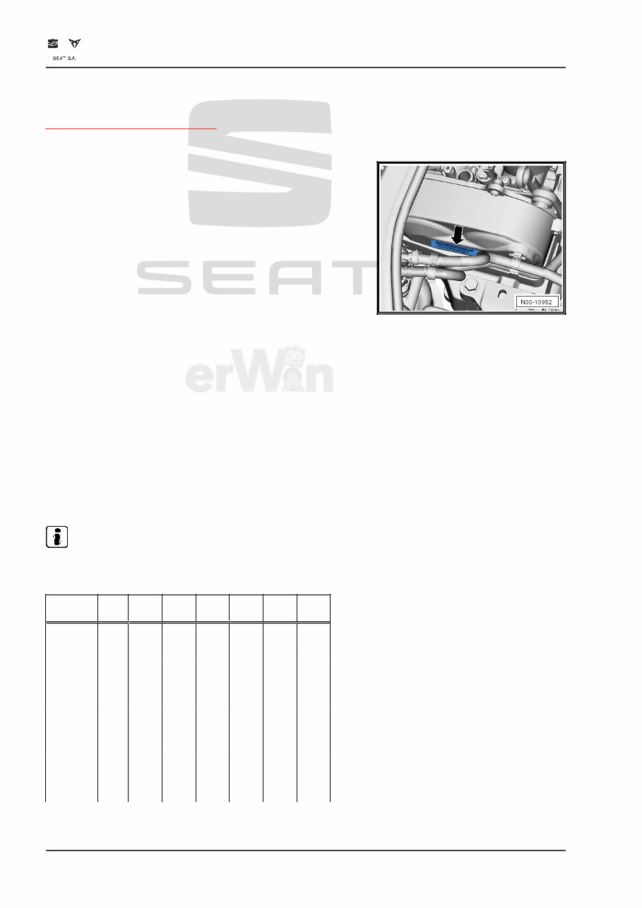
2.1 Engine number, engine data
The engine code is also on the vehicle data sticker and on the
crankcase above the gearbox.
The engine number consists of up to 9 characters (alphanumer‐
ic). The first 3 letter part makes up the “engine code”. The sec‐
ond 6-character part makes up the “serial number”. If more than
999,999 engines were produced with the same code letters, the
first of the six digits is replaced by a letter.
Vehicles with four digit engine codes
Four-place engine codes are being introduced, starting with let‐
ter “C”. The first 3 places show the mechanical design of engine
and are stamped on the engine as previously. The fourth digit
indicates the output and the torque of the engine. The engine
performance depends on the engine control unit -J623-. The
four-digit engine code can be found on the identification plate,
the vehicle data sticker and on the engine control unit.
Note
The fitting locations for the vehicle data stickers may be found
in the ⇒ Maintenance; Booklet ; documentation.
Engine
code
CHP
A
CMB
A
CXS
A
CZC
A
CZE
A
CZD
A
DJKA
Exhaust
emission
standard
EU5 EU5 EU5 EU6 EU6 EU6 EU6A
G
Dis‐
plac
eme
nt
cm
3
1395 1395 1395 1395 1395 1395 1395
Pow
er
kW
at
rpm
103/
4500
-600
0
90/50
00-60
00
90/50
00-60
00
92/50
00-60
00
110/5
000-6
000
110/5
000-6
000
110/5
000
Tor‐
que
Nm
at
rpm
250/
1500
-350
0
200/1
400
to
4000
200/1
400
to
4000
200/1
400
to
4000
250/1
500-3
500
250/1
500-3
500
250/1
500
to
4000
Ateca 2017 ➤, Ateca 2021 ➤, Cupra Ateca 2021 ➤, Cupra Leon 2020 ➤, Cupra Leon S ...
4-cylinder petrol engine (1.4 l direct injection, 4 V, turbocharger, EA211) - Edition 01.2023
4 Rep. gr.00 - Technical data
You're Reading a Preview
What's Included?
Fast Download Speeds
Online & Offline Access
Access PDF Contents & Bookmarks
Full Search Facility
Print one or all pages of your manual
$52.99
Viewed 71 Times Today


Secure transaction
What's Included?
Fast Download Speeds
Online & Offline Access
Access PDF Contents & Bookmarks
Full Search Facility
Print one or all pages of your manual
$52.99
The 2023 SEAT Leon Cupra Service & Repair Manual is a detailed guide for both professional mechanics and DIY enthusiasts. This manual provides step-by-step instructions, troubleshooting charts, exploded-view illustrations, wiring diagrams, and clear images to help you maintain and repair your vehicle.
- Suitable for both professionals and DIYers
- Manufacturer-sourced procedures ensure accuracy and reliability
- Easy to navigate and use, with digital copies available for convenient access
- Contains detailed information on engine, transmission, basic maintenance, suspension, starting and charging, steering, fuel, supplemental restraint, cooling, braking, HVAC, electric, exhaust, and more
- Printer-friendly format makes it easy to print out specific pages or sections
- Compatible with all computers and electronic devices
This manual is designed to help you maintain and repair your SEAT Leon Cupra, ensuring it remains in top condition. Whether you're a professional mechanic or a DIY enthusiast, this guide has everything you need to get the job done right.


