

2005 Scion xA Service & Repair Manual
What's Included?
Fast Download Speeds
Offline Viewing
Access Contents & Bookmarks
Full Search Facility
Print one or all pages of your manual
INTRODUCTION – REPAIR INSTRUCTION
IN–21
IN
VEHICLE LIFT AND SUPPORT
LOCATIONS
1. NOTICE ABOUT VEHICLE CONDITION WHEN
JACKING UP VEHICLE
(a) The vehicle must be unloaded before jacking up /
lifting up the vehicle. Never jack up / lift up a heavily
loaded vehicle.
(b) When removing heavy parts such as the engine and
transmission, the center of gravity of the vehicle
may shift. To stabilize the vehicle, place a balance
weight in a location where it will not roll or shift, or
use a mission jack to hold the jacking support.
2. NOTICE FOR USING 4 POST LIFT
(a) Follow the safety procedures outlined in the lift
instruction manual.
(b) Use precautionary measures to prevent the free
wheel beam from damaging tires or wheels.
(c) Use wheel chocks to secure the vehicle.
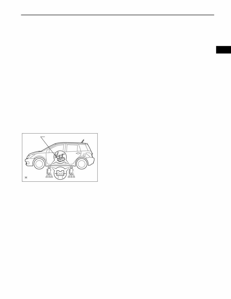
3. NOTICE FOR USING JACK AND SAFETY STAND
(a) Work on a level surface. Use wheel chocks at all
times.
(b) Use safety stands with rubber attachments as
shown in the illustration.
(c) Set the jack and safety stands to the specified
locations of the vehicle accurately.
(d) When jacking up the vehicle, first release the
parking brake and move the shift lever to N.
(e) When jacking up the entire vehicle:
• When jacking up the front wheels first, make sure
wheel chocks are behind the rear wheels.
• When jacking up the rear wheels first, make sure
wheel chocks are in front of the front wheels.
(f) When jacking up only the front or rear wheels of the
vehicle:
• Before jacking up the front wheels, place wheel
chocks on both sides of the rear wheels.
• Before jacking up the rear wheels, place wheel
chocks on both sides of the front wheels.
(g) When lowering a vehicle that only has its front or
rear wheels jacked up:
• Before lowering the front wheels, make sure
wheel chocks are in front of the rear wheels.
• Before lowering the rear wheels, make sure
wheel chocks are behind the front wheels.
Rubber Attachment
D100678E01
IN–22
INTRODUCTION – REPAIR INSTRUCTION
IN
(h) It is extremely dangerous to perform any work on a
vehicle raised on a jack alone, even for work that
can be finished quickly. Safety stands must be used
to support it.
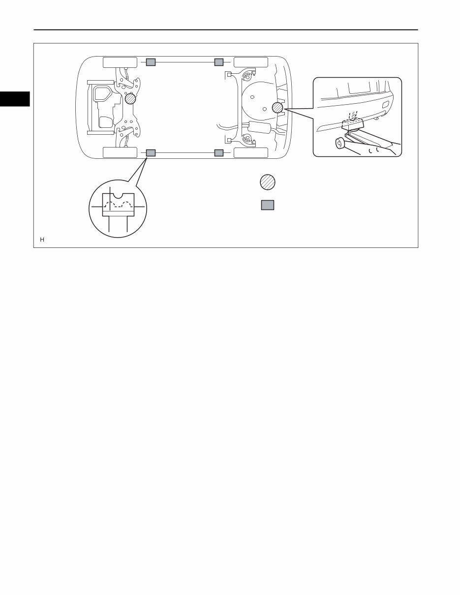
4. NOTICE FOR USING SWING ARM TYPE LIFT
(a) Follow safety procedures outlined in its instruction
manual.
(b) Use a swing arm equipped with a rubber
attachment, as shown in the illustration.
(c) When using the lift, make sure that the vehicle is
stabilized so that it will not tilt while work is being
performed. Stabilize the vehicle by adjusting the lift
arm's length and vehicle's position.
: Jack position
: Support position, pantograph
jack position
D100679E01
INTRODUCTION – REPAIR INSTRUCTION
IN–23
IN
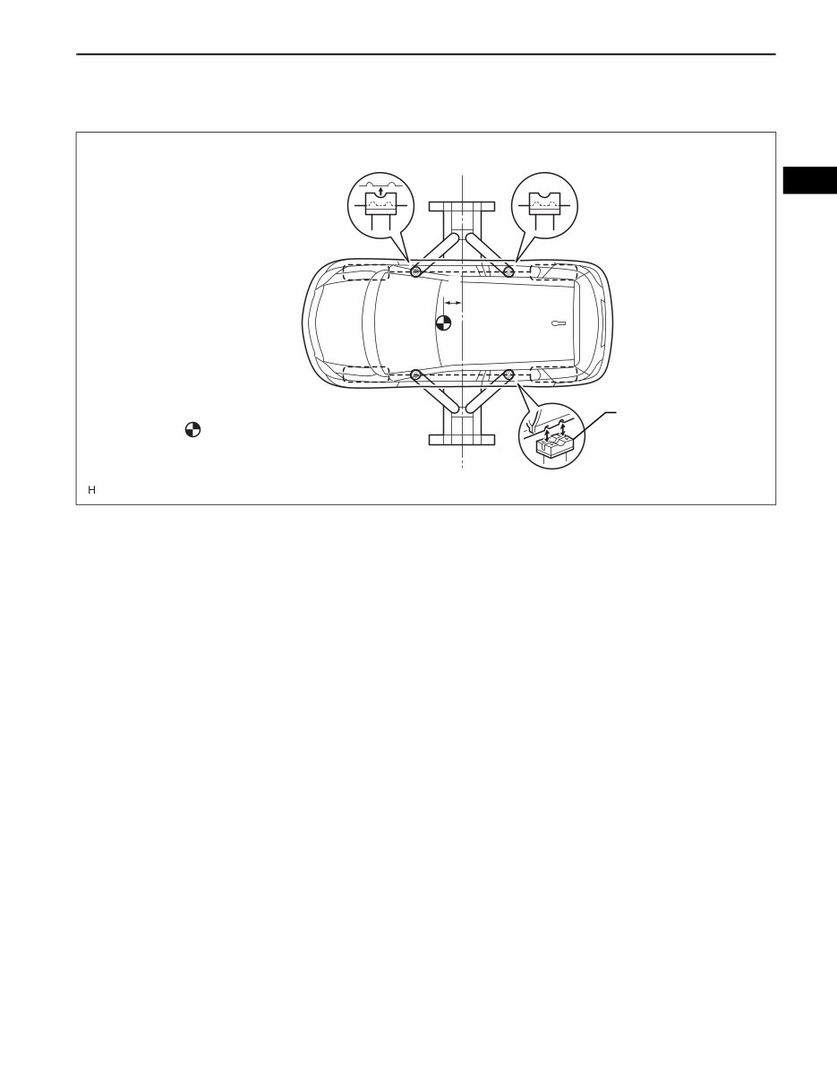
(d) When using the lift, its center should be as close to
the vehicle's center of gravity as possible (length of
"L" in the illustration should be as short as possible).
(e) Set the vehicle on the lift as level as possible. Then
match the groove of the cradle to the rigid rack
support location.
(f) Be sure to lock the swing arms before lifting and
during work (if equipped with arm locks).
(g) Lift the vehicle up off the ground. Stand at a safe
distance and shake the vehicle to check its stability.
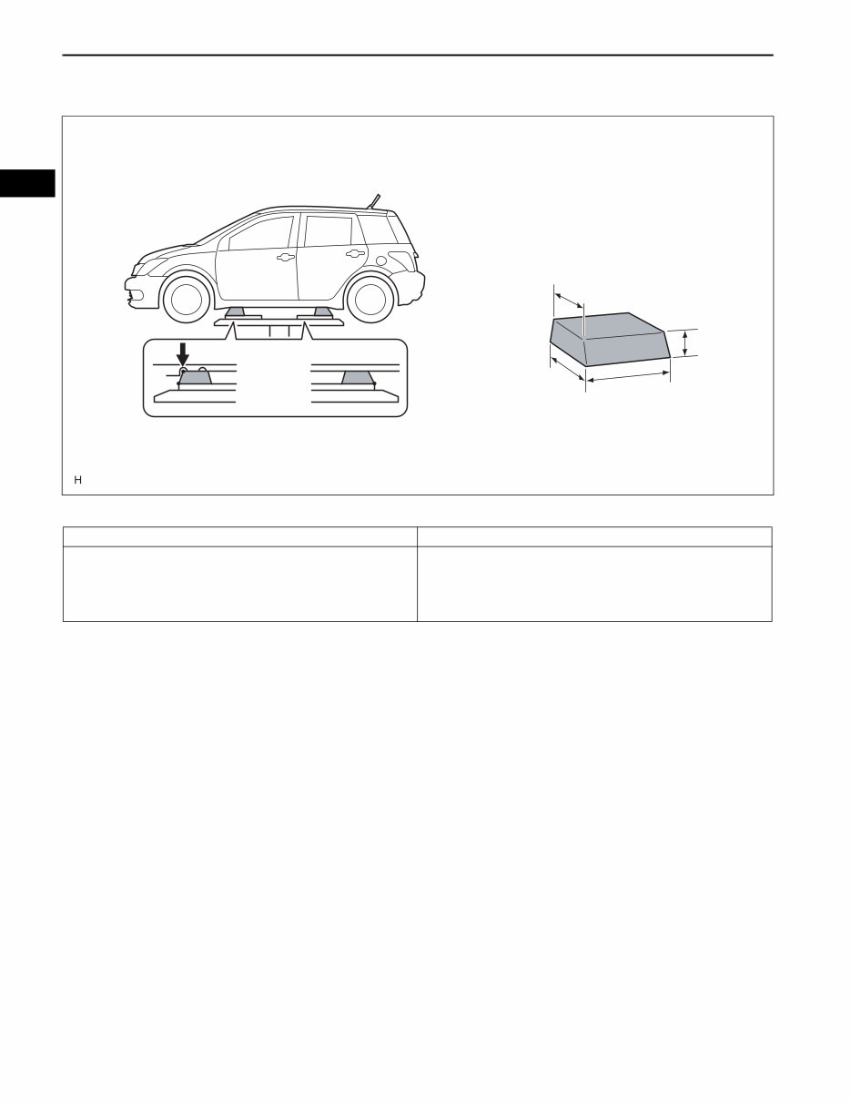
5. NOTICE FOR USING PLATE TYPE LIFT
(a) Follow safety procedures outlined in its instruction
manual.
(b) Use plate lift attachments (rubber lifting blocks) on
top of the plate surface.
: Center of vehicle gravity
(unloaded condition)
Rubber Attachment
Center of Lift
L
D100680E01
IN–24
INTRODUCTION – REPAIR INSTRUCTION
IN
(c) Refer to the illustration below to determine how to
properly set the vehicle.
HINT:
(d) Use the lift to raise the vehicle up off the ground,
and shake it to make sure that it is stable.
Attachment
Attachment Dimensions
85 mm (3.35 in.)
100 mm (3.94 in.)
200 mm (7.87 in.)
70 mm
(2.76 in.)
B
A
C
D100687E01
Right and left set position Place the vehicle over the center of the lift.
Front and rear set position Place the attachments at the ends of the rubber plate surface, under
the vehicle lift pad (A and C in the illustration). Raise the plate slightly
and reposition the vehicle so the top of the attachment (B in the
illustration) is aligned with the front side notch in the vehicle rocker
flange.

INTRODUCTION – REPAIR INSTRUCTION
IN–25
IN
INITIALIZATION
1. RESET SLIDING ROOF DRIVE GEAR (MOTOR)
NOTICE:
The sliding roof drive gear (motor) must be reset
(pulse sensor's location must be set) when one of
the following occurs: 1) the battery cable has been
disconnected, 2) the drive gear connector is
connected/disconnected, or 3) the sliding roof is
replaced or installed/removed. If the drive gear is not
reset, the AUTO function will not operate.
(a) The sliding roof AUTO operation and the jam
protection function may not operate normally if the
battery cable is disconnected/reconnected, or the
battery is replaced or recharged. Initialize the sliding
roof system using the method below.
(1) Turn the ignition switch ON.
(2) Fully open the sliding roof.
(3) Press and hold the sliding roof motor switch on
the SLIDE/OPEN side for 2 seconds or more.
The sliding roof control ECU built into the drive
gear will memorize the position of the sliding
roof. Initialization is now complete.
HINT:
If the battery cable is disconnected, the sliding
roof control ECU may not detect the position of
the roof glass. If the sliding roof AUTO operation
is still disabled even after the drive gear has
been initialized, the Hall IC may be
malfunctioning. The Hall IC is built into the drive
gear and detects the roof glass position. If the
result is not as specified, replace the drive gear
assembly (sliding roof control ECU).
System Name
Sliding Roof System
IN–34
INTRODUCTION – HOW TO TROUBLESHOOT ECU CONTROLLED SYSTEMS
IN
ELECTRONIC CIRCUIT INSPECTION
PROCEDURE
1. BASIC INSPECTION
(a) WHEN MEASURING RESISTANCE OF
ELECTRONIC PARTS
(1) Unless otherwise stated, all resistance
measurements should be made at an ambient
temperature of 20°C (68°F). Resistance
measurements may be inaccurate if measured
at high temperatures, i.e. immediately after the
vehicle has been running. Measurements should
be made after the engine has cooled down.
(b) HANDLING CONNECTORS
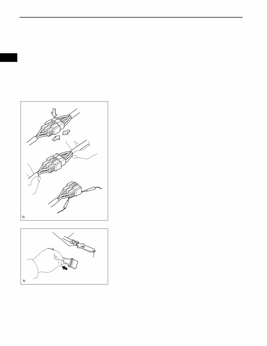
(1) When disconnecting a connector, first squeeze
the mating halves tightly together to release the
lock, and then press the lock claw and separate
the connector.
(2) When disconnecting a connector, do not pull on
the harnesses. Grasp the connector directly and
separate it.
(3) Before connecting a connector, check that there
are no deformed, damaged, loose or missing
terminals.
(4) When connecting a connector, press firmly until
it locks with a "click" sound.
(5) If checking a connector with a TOYOTA
electrical tester, check the connector from the
backside (harness side) using a mini test lead.
NOTICE:
• As a waterproof connector cannot be
checked from the backside, check it by
connecting a sub-harness.
• Do not damage the terminals by moving
the inserted tester needle.
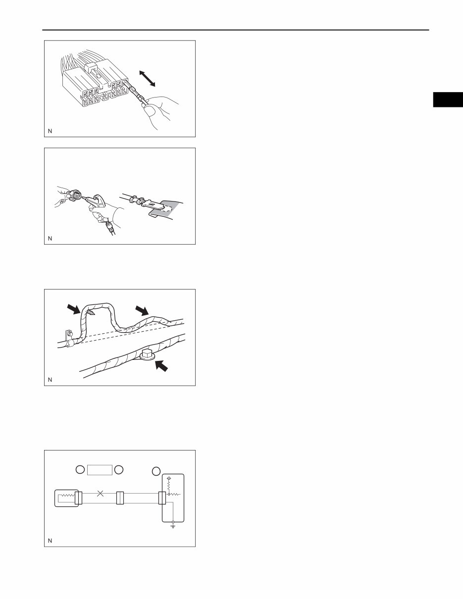
(c) CHECKING CONNECTORS
(1) Checking when a connector is connected:
Squeeze the connector together to confirm that
they are fully connected and locked.
(2) Checking when a connector is disconnected:
Check by pulling the wire harness lightly from
the backside of the connector. Look for
unlatched terminals, missing terminals, loose
crimps or broken conductor wires. Check
visually for corrosion, metallic or foreign matter
and water, and bent, rusted, overheated,
contaminated, or deformed terminals.
INCORRECT
INCORRECT
CORRECT
D100803E01
Core Wire
Terminal
Deformation
Pull Lightly
Looseness of
Crimping
D100734E01
INTRODUCTION – HOW TO TROUBLESHOOT ECU CONTROLLED SYSTEMS
IN–35
IN
(3) Checking the contact pressure of the terminal:
Prepare a spare male terminal. Insert it into a
female terminal, and check for ample tension
when inserting and after full engagement.
NOTICE:
When testing a gold-plated female terminal,
always use a gold-plated male terminal.
(d) REPAIR METHOD OF CONNECTOR TERMINAL
(1) If there is any foreign matter on the terminal,
clean the contact point using an air gun or cloth.
Never rub the contact point using sandpaper as
the plating may come off.
(2) If there is abnormal contact pressure, replace
the female terminal. If the male terminal is gold-
plated (gold color), use a gold-plated female
terminal; if it is silver-plated (silver color), use a
silver-plated female terminal.
(3) Damaged, deformed, or corroded terminals
should be replaced. If the terminal does not lock
into the housing, the housing may have to be
replaced.
(e) HANDLING OF WIRE HARNESS
(1) If removing a wire harness, check the wiring and
clamping before proceeding so that it can be
restored in the same way.
(2) Never twist, pull or slacken the wire harness
more than necessary.
(3) The wire harness should never come into
contact with a high temperature part, or rotating,
moving, vibrating or sharp-edged parts. Avoid
contact with panel edges, screw tips and other
sharp items.
(4) When installing parts, never pinch the wire
harness.
(5) Never cut or break the cover of the wire harness.
If it is cut or broken, replace it or repair it with
vinyl tape.
2. CHECK FOR OPEN CIRCUIT
(a) For an open circuit in the wire harness in Fig. 1,
check the resistance or voltage, as described below.
D100735
INCORRECT CORRECT
D100736E01
INCORRECT INCORRECT
INCORRECT
D100784E01
Fig. 1
OPEN C B
A
ECU
SENSOR
1
2
1
2
1
2
1
2
D100785E01
IN–36
INTRODUCTION – HOW TO TROUBLESHOOT ECU CONTROLLED SYSTEMS
IN
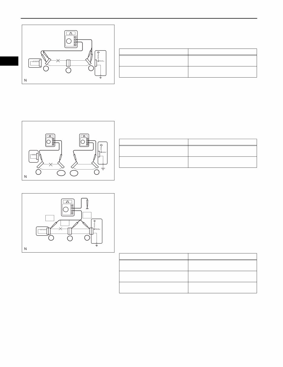
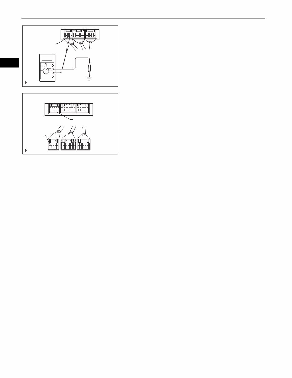
(b) Check the resistance.
(1) Disconnect connectors A and C, and measure
the resistance between them.
Standard resistance (Fig. 2)
HINT:
Measure the resistance while lightly shaking the
wire harness vertically and horizontally.
If the results match the examples above, an
open circuit exists between terminal 1 of
connector A and terminal 1 of connector C.
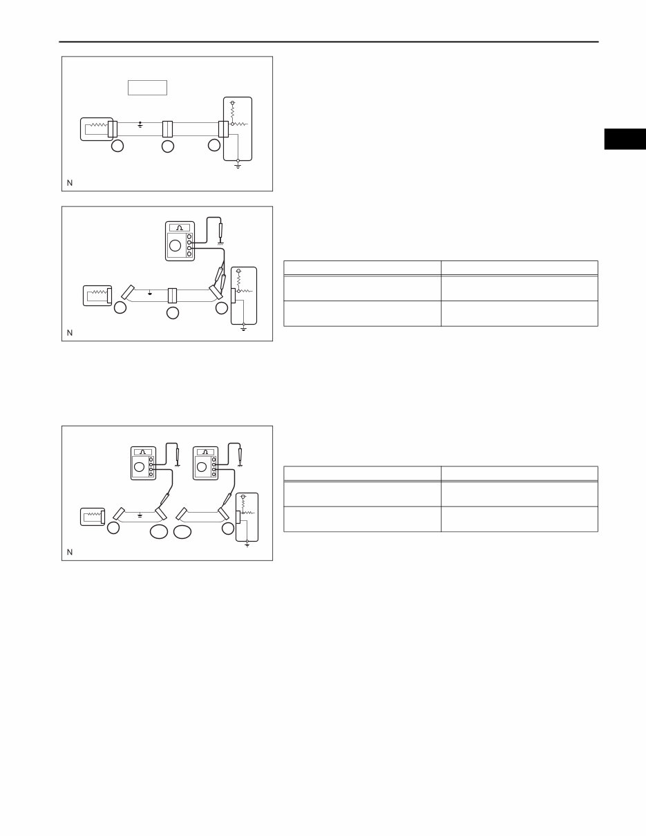
(2) Disconnect connector B and measure the
resistance between the connectors.
Standard resistance (Fig. 3)
If the results match the examples above, an
open circuit exists between terminal 1 of
connector B2 and terminal 1 of connector C.
(c) Check the voltage.
(1) In a circuit in which voltage is applied to the ECU
connector terminal, an open circuit can be
checked by conducting a voltage check.
With each connector still connected, measure
the voltage between the body ground and these
terminals (in this order): 1) terminal 1 of
connector A, 2) terminal 1 of connector B, and 3)
terminal 1 of connector C.
Standard voltage (Fig. 4)
If the results match the examples above, an
open circuit exists in the wire harness between
terminal 1 of connector B and terminal 1 of
connector C.
Fig. 2
ECU
1
2
1
2
1
2
SENSOR
C
B
A
D100786E01
Tester Connection Specified Condition
Connector A terminal 1 - Connector
C terminal 1
10 kΩ or higher
Connector A terminal 2 - Connector
C terminal 2
Below 1 Ω
Fig. 3
SENSOR
ECU
C
1 1
2 2
1 1
2 2
B2 B1
A
D100787E01
Tester Connection Specified Condition
Connector A terminal 1 - Connector
B1 terminal 1
Below 1 Ω
Connector B2 terminal 1 - Connector
C terminal 1
10 kΩ or higher
Fig. 4
ECU
5 V
5 V
0 V
SENSOR
1
1
2 2 2 2
C A
B
D100788E01
Tester Connection Specified Condition
Connector A terminal 1 - Body
ground
5 V
Connector B terminal 1 - Body
ground
5 V
Connector C terminal 1 - Body
ground
Below 1 V
INTRODUCTION – HOW TO TROUBLESHOOT ECU CONTROLLED SYSTEMS
IN–37
IN
3. CHECK FOR SHORT CIRCUIT
(a) If the wire harness is ground shorted (Fig. 5), locate
the section by conducting a resistance check with
the body ground (below).
(b) Check the resistance with the body ground.
(1) Disconnect connectors A and C, and measure
the resistance.
Standard resistance (Fig. 6)
HINT:
Measure the resistance while lightly shaking the
wire harness vertically and horizontally.
If the results match the examples above, a short
circuit exists between terminal 1 of connector A
and terminal 1 of connector C.
(2) Disconnect connector B and measure the
resistance.
Standard resistance (Fig. 7)
If the results match the examples above, a short
circuit exists between terminal 1 of connector B2
and terminal 1 of connector C.
4. CHECK AND REPLACE ECU
NOTICE:
• The connector should not be disconnected from
the ECU. Perform the inspection from the
backside of the connector on the wire harness
side.
• When no measuring condition is specified,
perform the inspection with the engine stopped
and the ignition switch ON.
• Check that the connectors are fully seated. Check
for loose, corroded or broken wires.
Fig. 5
SHORT
ECU
C B
A
1
2
1
2
1
2
D100789E01
Fig. 6
SENSOR
ECU
C
B
A
1 1 1
2 2 2
D100790E01
Tester Connection Specified Condition
Connector A terminal 1 - Body
ground
Below 1 Ω
Connector A terminal 2 - Body
ground
10 kΩ or higher
Fig. 7
SENSOR
ECU
1 1
2 2
1 1
2 2
C A
B1 B2
D100800E01
Tester Connection Specified Condition
Connector A terminal 1 - Body
ground
10 kΩ or higher
Connector B2 terminal 1 - Body
ground
Below 1 Ω
IN–38
INTRODUCTION – HOW TO TROUBLESHOOT ECU CONTROLLED SYSTEMS
IN
(a) First, check the ECU ground circuit. If it is faulty,
repair it. If it is normal, the ECU could be faulty.
Temporarily replace the ECU with a normally
functioning one and check if the symptoms occur. If
the trouble symptoms disappear, replace the
original ECU.
(1) Measure the resistance between the ECU
ground terminal and body ground.
Standard resistance:
Below 1 Ω
(2) Disconnect the ECU connector. Check the
ground terminal on the ECU side and wire
harness side for bending, corrosion or foreign
matter. Lastly, check the contact pressure of the
female terminals.
Example:
Ground
D100801E01
ECU Side
Wire Harness Side
Ground
Ground
D100802E02
You're Reading a Preview
What's Included?
Fast Download Speeds
Offline Viewing
Access Contents & Bookmarks
Full Search Facility
Print one or all pages of your manual
$36.99
Viewed 27 Times Today


Secure transaction
What's Included?
Fast Download Speeds
Offline Viewing
Access Contents & Bookmarks
Full Search Facility
Print one or all pages of your manual
$36.99
- The 2005 Scion xA Service & Repair Manual is a comprehensive guide for fixing vehicle issues using a Do-It-Yourself approach.
- It includes troubleshooting and replacement procedures recommended by the manufacturer, along with step-by-step instructions, clear images, and exploded-view illustrations.
- Regular maintenance is essential for the durability of your vehicle, and this manual provides the manufacturer's recommended troubleshooting charts and replacement procedures.
- By using this manual, you can save on repairs, increase your vehicle’s reliability, and reduce the frequency of visits to the repair shop.
- It eliminates the need to search through numerous pages for specific information and offers the convenience of digital access, allowing you to carry, search, screenshot, and bookmark the content.
- Additionally, the manual is printable and compatible with various electronic devices, including PC & Mac computers, Android and Apple smartphones & tablets, etc. It requires Adobe Reader, which is available for free.


