

INTRODUCTION – REPAIR INSTRUCTION
IN–21
IN
VEHICLE LIFT AND SUPPORT
LOCATIONS
1. NOTICE ABOUT VEHICLE CONDITION WHEN
JACKING UP VEHICLE
(a) The vehicle must be unloaded before jacking up /
lifting up the vehicle. Never jack up / lift up a heavily
loaded vehicle.
(b) When removing heavy parts such as the engine and
transmission, the center of gravity of the vehicle
may shift. To stabilize the vehicle, place a balance
weight in a location where it will not roll or shift, or
use a mission jack to hold the jacking support.
2. NOTICE FOR USING 4 POST LIFT
(a) Follow the safety procedures outlined in the lift
instruction manual.
(b) Use precautionary measures to prevent the free
wheel beam from damaging tires or wheels.
(c) Use wheel chocks to secure the vehicle.
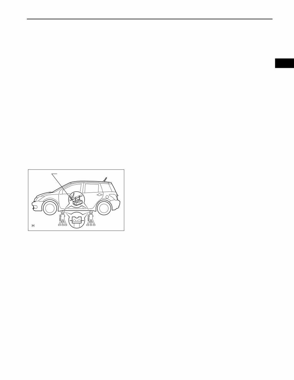
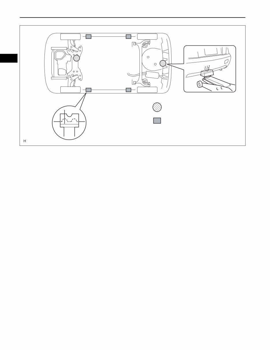
3. NOTICE FOR USING JACK AND SAFETY STAND
(a) Work on a level surface. Use wheel chocks at all
times.
(b) Use safety stands with rubber attachments as
shown in the illustration.
(c) Set the jack and safety stands to the specified
locations of the vehicle accurately.
(d) When jacking up the vehicle, first release the
parking brake and move the shift lever to N.
(e) When jacking up the entire vehicle:
• When jacking up the front wheels first, make sure
wheel chocks are behind the rear wheels.
• When jacking up the rear wheels first, make sure
wheel chocks are in front of the front wheels.
(f) When jacking up only the front or rear wheels of the
vehicle:
• Before jacking up the front wheels, place wheel
chocks on both sides of the rear wheels.
• Before jacking up the rear wheels, place wheel
chocks on both sides of the front wheels.
(g) When lowering a vehicle that only has its front or
rear wheels jacked up:
• Before lowering the front wheels, make sure
wheel chocks are in front of the rear wheels.
• Before lowering the rear wheels, make sure
wheel chocks are behind the front wheels.
Rubber Attachment
D100678E01
IN–22
INTRODUCTION – REPAIR INSTRUCTION
IN
(h) It is extremely dangerous to perform any work on a
vehicle raised on a jack alone, even for work that
can be finished quickly. Safety stands must be used
to support it.
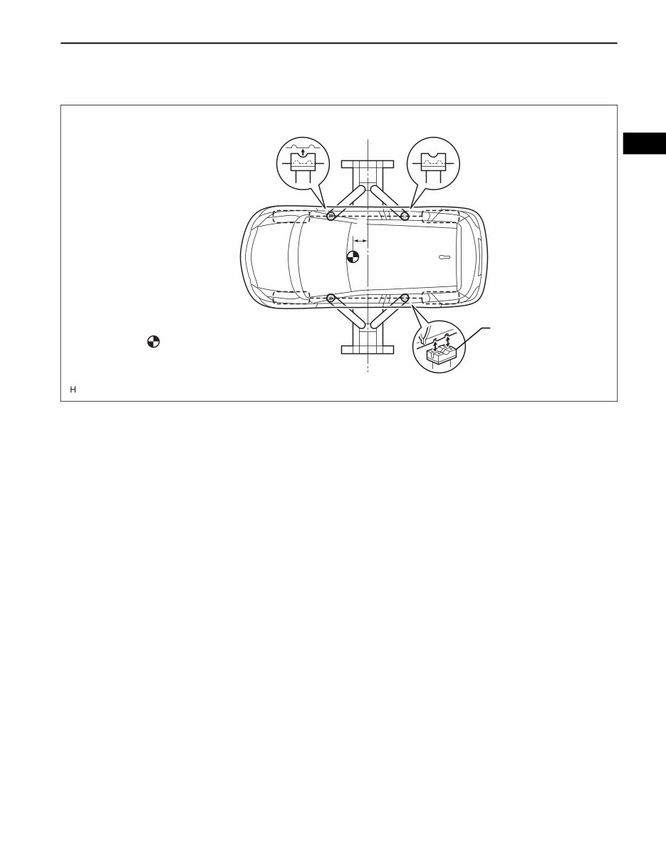
4. NOTICE FOR USING SWING ARM TYPE LIFT
(a) Follow safety procedures outlined in its instruction
manual.
(b) Use a swing arm equipped with a rubber
attachment, as shown in the illustration.
(c) When using the lift, make sure that the vehicle is
stabilized so that it will not tilt while work is being
performed. Stabilize the vehicle by adjusting the lift
arm's length and vehicle's position.
: Jack position
: Support position, pantograph
jack position
D100679E01
INTRODUCTION – REPAIR INSTRUCTION
IN–23
IN
(d) When using the lift, its center should be as close to
the vehicle's center of gravity as possible (length of
"L" in the illustration should be as short as possible).
(e) Set the vehicle on the lift as level as possible. Then
match the groove of the cradle to the rigid rack
support location.
(f) Be sure to lock the swing arms before lifting and
during work (if equipped with arm locks).
(g) Lift the vehicle up off the ground. Stand at a safe
distance and shake the vehicle to check its stability.
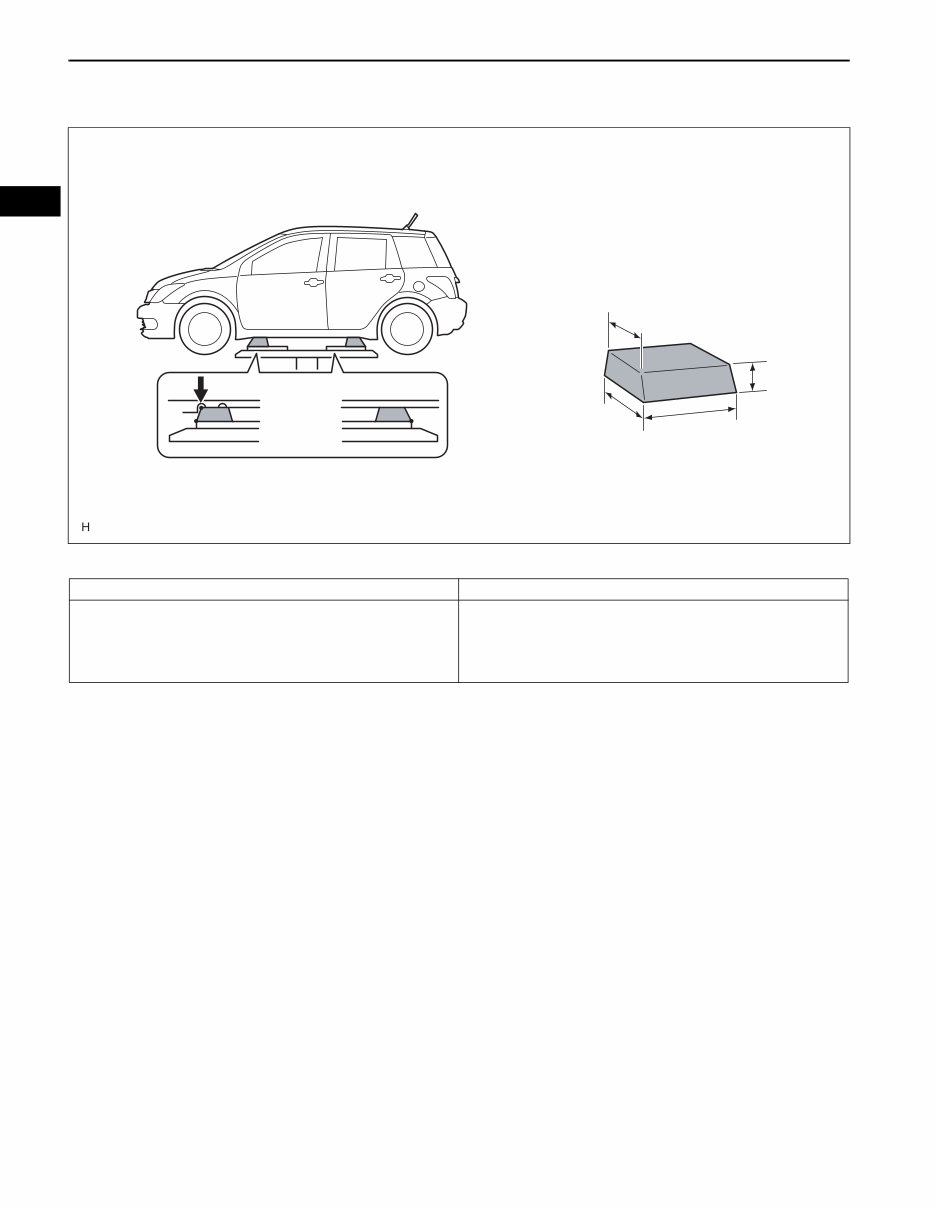
5. NOTICE FOR USING PLATE TYPE LIFT
(a) Follow safety procedures outlined in its instruction
manual.
(b) Use plate lift attachments (rubber lifting blocks) on
top of the plate surface.
: Center of vehicle gravity
(unloaded condition)
Rubber Attachment
Center of Lift
L
D100680E01
IN–24
INTRODUCTION – REPAIR INSTRUCTION
IN
(c) Refer to the illustration below to determine how to
properly set the vehicle.
HINT:
(d) Use the lift to raise the vehicle up off the ground,
and shake it to make sure that it is stable.
Attachment
Attachment Dimensions
85 mm (3.35 in.)
100 mm (3.94 in.)
200 mm (7.87 in.)
70 mm
(2.76 in.)
B
A
C
D100687E01
Right and left set position Place the vehicle over the center of the lift.
Front and rear set position Place the attachments at the ends of the rubber plate surface, under
the vehicle lift pad (A and C in the illustration). Raise the plate slightly
and reposition the vehicle so the top of the attachment (B in the
illustration) is aligned with the front side notch in the vehicle rocker
flange.

INTRODUCTION – REPAIR INSTRUCTION
IN–25
IN
INITIALIZATION
1. RESET SLIDING ROOF DRIVE GEAR (MOTOR)
NOTICE:
The sliding roof drive gear (motor) must be reset
(pulse sensor's location must be set) when one of
the following occurs: 1) the battery cable has been
disconnected, 2) the drive gear connector is
connected/disconnected, or 3) the sliding roof is
replaced or installed/removed. If the drive gear is not
reset, the AUTO function will not operate.
(a) The sliding roof AUTO operation and the jam
protection function may not operate normally if the
battery cable is disconnected/reconnected, or the
battery is replaced or recharged. Initialize the sliding
roof system using the method below.
(1) Turn the ignition switch ON.
(2) Fully open the sliding roof.
(3) Press and hold the sliding roof motor switch on
the SLIDE/OPEN side for 2 seconds or more.
The sliding roof control ECU built into the drive
gear will memorize the position of the sliding
roof. Initialization is now complete.
HINT:
If the battery cable is disconnected, the sliding
roof control ECU may not detect the position of
the roof glass. If the sliding roof AUTO operation
is still disabled even after the drive gear has
been initialized, the Hall IC may be
malfunctioning. The Hall IC is built into the drive
gear and detects the roof glass position. If the
result is not as specified, replace the drive gear
assembly (sliding roof control ECU).
System Name
Sliding Roof System
You're Reading a Preview
What's Included?
 Lifetime Access
Fast Download Speeds
Offline Viewing
Access Contents & Bookmarks
Full Search Facility
Print one or all pages of your manual
$36.99
2005 Scion xA Service & Repair Manual
Viewed 27 Times Today

What's Included?
Lifetime Access
Fast Download Speeds
Offline Viewing
Access Contents & Bookmarks
Full Search Facility
Print one or all pages of your manual
$36.99

Secure transaction
What's Included?
Lifetime Access
Fast Download Speeds
Offline Viewing
Access Contents & Bookmarks
Full Search Facility
Print one or all pages of your manual
Description
- The 2005 Scion xA Service & Repair Manual is a comprehensive guide for fixing vehicle issues using a Do-It-Yourself approach.
- It includes troubleshooting and replacement procedures recommended by the manufacturer, along with step-by-step instructions, clear images, and exploded-view illustrations.
- Regular maintenance is essential for the durability of your vehicle, and this manual provides the manufacturer's recommended troubleshooting charts and replacement procedures.
- By using this manual, you can save on repairs, increase your vehicle’s reliability, and reduce the frequency of visits to the repair shop.
- It eliminates the need to search through numerous pages for specific information and offers the convenience of digital access, allowing you to carry, search, screenshot, and bookmark the content.
- Additionally, the manual is printable and compatible with various electronic devices, including PC & Mac computers, Android and Apple smartphones & tablets, etc. It requires Adobe Reader, which is available for free.


