

1997-2006 SAAB 9-5 Service & Repair Manual
What's Included?
Fast Download Speeds
Offline Viewing
Access Contents & Bookmarks
Full Search Facility
Print one or all pages of your manual
1999-2000 ENGINES
3.0L V6
ENGINE IDENTIFICATION
Vehicle Identification Number (VIN) is located on top left end of instrument panel, visible through windshield.
Engine code is eighth character from left of VIN. See ENGINE IDENTIFICATION CODES table.
ENGINE IDENTIFICATION CODES
ADJUSTMENTS
VALVE CLEARANCE ADJUSTMENT
Engines are equipped with hydraulic valve lifters. No adjustment is required.
TROUBLE SHOOTING
To trouble shoot mechanical engine components, see appropriate table in TROUBLE SHOOTING article in
GENERAL INFORMATION.
REMOVAL & INSTALLATION
FUEL PRESSURE RELEASE
NOTE: For repair procedures not covered in this article, see ENGINE OVERHAUL
PROCEDURES article in GENERAL INFORMATION.
Application Code
3.0L Z
CAUTION: When battery is disconnected, vehicle computer and memory systems
may lose memory data. Driveability problems may exist until computer
systems have completed a relearn cycle. See appropriate article under
COMPUTER RELEARN PROCEDURES in GENERAL INFORMATION.
NOTE: For reassembly reference, label all electrical connectors, vacuum hoses and
fuel lines before removal. Also place mating marks on engine hood and other
major assemblies before removal.
WARNING: Residual fuel pressure may be present in fuel system when engine is off.
To avoid fire hazard, wrap a shop towel around fuel fitting before
disconnecting fuel lines.
2000 Saab 9-5
1999-2000 ENGINES 3.0L V6
2000 Saab 9-5
1999-2000 ENGINES 3.0L V6

To release fuel pressure, disconnect fuel lines at fuel pressure regulator and fuel injection manifold.
ENGINE
Removal
1. Remove engine covers. Remove battery. Unhook front electrical distribution box from battery shelf.
Disconnect cruise control cable from throttle lever. Remove positive terminal block from battery shelf.
Remove clamp for positive battery cable. Remove vacuum hose from clamps on battery shelf.
2. Remove battery cable conduit clips. Unbolt battery shelf. Raise battery shelf slightly and disconnect
cruise control electrical connector. Remove battery shelf with cruise control module and cable.
3. Release throttle cable from bracket. Snap out control rod, release bracket, and fold to one side. Remove
hose clamps between inlet pipes and intake manifold, and between resonator and Mass Airflow (MAF)
sensor. Slightly lift inlet pipes. Disconnect vacuum hoses and electrical connectors. Remove pipes and
resonators.
4. Disconnect secondary air injection hoses from check valves. Cut cable tie at resonator bracket. Remove
seal from detachable bulkhead plate. Remove cover and disconnect washer hoses. Disconnect fuel pipe
clamps from detachable bulkhead plate. Remove bolts and lift up plate.
5. Disconnect Motronic Electronic Control Module (ECM) electrical connector. Pull wiring through to
engine compartment. Remove detachable bulkhead plate. Disconnect wiring from torque arm engine
mounting. Lift off power steering servo oil reservoir and remove torque arm. Turn tensioner pulley
forward and release tension load. Move belt to one side.
6. Remove power steering pump. Remove clamp from servo pipe. Move pump and reservoir to one side. On
A/T equipped vehicles, disconnect gear selector cable. Disconnect transmission cooling lines and drain
fluid. Plug hoses. On all vehicles, disconnect rear HO2S sensor connector. Disconnect fuel hoses. See
FUEL PRESSURE RELEASE . Loosen expansion tank cap.
7. Raise and support front of vehicle. Remove both front wheels. Disconnect steering knuckles from
MacPherson struts. Remove inner CV joint boot clamps. Pull CV joints apart. Cover CV joint halves.
Raise vehicle further. Remove clamp holding HO2S, knock sensor, and crankshaft position sensor wiring
to cylinder block. Disconnect HO2S, knock sensor, and crankshaft position sensor electrical connectors.
8. Remove front exhaust pipe. Remove center air shield. Drain coolant. Loosen lower and upper A/C
compressor retaining bolts. On A/T equipped vehicles, move oil cooling lines forward. On all vehicles,
lower vehicle.
9. Remove upper radiator hose from engine. Drain coolant from hose. Remove lower radiator hose from
engine and move hose forward. Remove heat exchanger hoses. Remove expansion tank hose. Lift up
power steering servo pump and oil reservoir. Remove brake servo vacuum hose from intake manifold.
10. Disconnect positive battery cable from positive terminal block. Disconnect battery ground cable from
gearbox. Remove remaining bolts on A/C compressor. Disconnect rear and right engine mounts. Install
Extender (83 94 439) on hood gas springs to hold hood open.
11. Hook Lifting Yoke (83 92 409) onto an engine lift and engine. Remove left engine mount. Lift entire
powertrain a short distance and remove resonator bracket. Remove entire powertrain.
NOTE: Remove engine and transaxle as a unit. Engine is removed through bottom of
vehicle.
2000 Saab 9-5
1999-2000 ENGINES 3.0L V6

Installation
1. Install multi-groove belt, ensuring it runs under right engine mount. Carefully lower powertrain into
engine compartment, ensuring engine is aligned with engine mounts.
2. Install resonator bracket. Install engine mount bolts. To install remaining components, reverse removal
procedure.
INTAKE & EXHAUST MANIFOLDS
REAR CYLINDER HEAD
Removal
1. Disconnect negative battery cable. Raise and support vehicle. Remove 2 bolts securing rear exhaust pipe
to exhaust manifold. Remove center air shield. Drain coolant. Lower vehicle. Remove engine covers.
Disconnect all components attached to intake manifold. Remove intake manifold bolts. Remove throttle
body preheater hoses, crankcase ventilation hose, and vacuum hoses from intake manifold.
2. Disconnect IAC valve connector. Remove fuel pressure regulator hose. Remove wiring harness conduit
under throttle body. Disconnect throttle position indicator connector and ignition coil. Disconnect throttle
body connector. Lift off intake manifold. Plug holes with paper.
3. Unplug injector connector. Disconnect camshaft position sensor. Disconnect fuel lines and plug
connectors. Remove bolts securing center intake manifold complete with fuel rail and place it to one side.
Mark lower section of intake manifold for reassembly reference. Remove lower intake manifold. Plug
holes with paper. Remove coolant manifold and bend aside. Disconnect spark plug wires.
4. Remove HO2S sensor from its holder. Remove crankcase ventilation housing. Plug holes with paper.
Remove steering servo oil reservoir. Disconnect wiring from torque arm engine mount. Remove torque
arm. Remove power steering servo line clamp from torque arm engine mount. Remove engine mount.
Remove upper hose from expansion tank. Remove upper part of generator air intake.
5. Slightly loosen crankshaft pulley bolts. Remove multi-groove belt, belt tensioner, power steering servo
pump, water pump pulley, and timing cover. Remove crankshaft pulley (do not remove center bolt). Put
cylinder No. 1 at TDC of compression stroke. Align matching marks on camshaft sprockets and timing
cover, and crankshaft. Lock camshaft sprockets in place.
6. Mark direction of rotation, and camshaft/crankshaft alignment marks on timing belt. Release belt tension
and remove belt. Turn crankshaft back 60 degrees BTDC. Remove bracket holding upper adjusting roller
and tensioning roller.
7. Remove timing cover, using care not to damage "O" rings. Remove cylinder head camshaft sprockets and
unscrew timing cover bolts from cylinder head. Camshaft sprockets are marked 1 and 2.
NOTE: For intake manifold and exhaust manifold removal and installation, see
appropriate cylinder head removal and installation procedure.
WARNING: Ensure wrench used to remove camshaft sprockets does not have
jaws that are too long. There is a risk of damaging casting, causing
tappet to jam.
2000 Saab 9-5
1999-2000 ENGINES 3.0L V6
8. Loosen exhaust camshaft bearing cap bolts in stages, one to one-half turn at a time. Remove camshaft
seal and lift out exhaust camshaft.
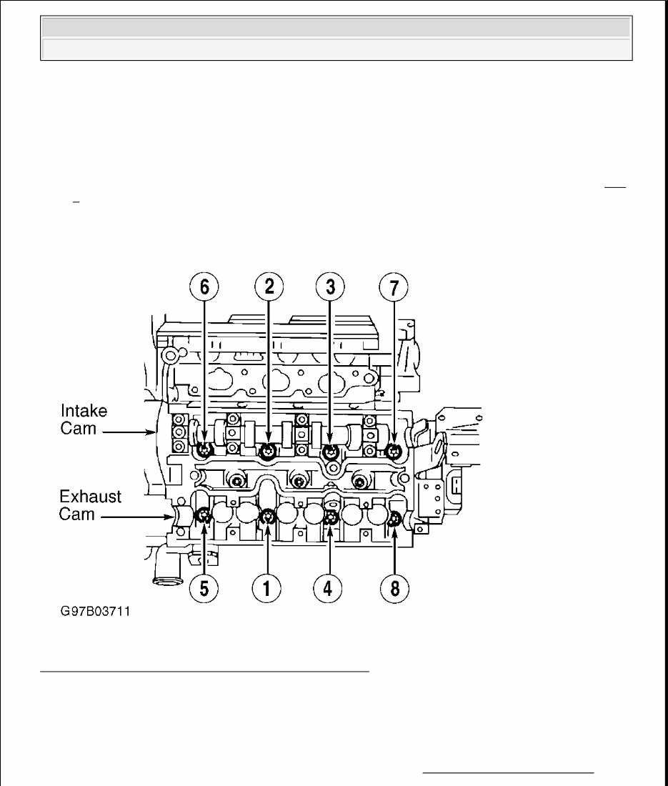
9. Loosen cylinder head bolts one-quarter, then one-half turn. Remove cylinder head bolts in order. See Fig.
1 . Remove cylinder head. Use care when placing cylinder head aside as intake camshaft is still in place
and valve stems could be bent. Remove intake camshaft, exhaust manifold and tappets.
Fig. 1: Cylinder Head Bolt Tightening/Loosening Sequence
Courtesy of SAAB-SCANIA OF AMERICA, INC.
Installation
1. Position crankshaft at 60 degrees BTDC. Clean all contact surfaces and install head gasket. Ensure gasket
is installed with mark OBEN/TOP facing upward. Install exhaust manifold and tappets. Place cylinder
head in position. Torque NEW bolts in order, to specification. See TORQUE SPECIFICATIONS . See
Fig. 1 .
NOTE: Intake camshaft removal is not necessary.
2000 Saab 9-5
1999-2000 ENGINES 3.0L V6
2. Install camshafts and lubricate with oil. Note markings on bearing caps and cylinder head. Install bearing
caps and tighten bolts in sequence, working outward. Lubricate seal lips and install gasket, camshaft bolt
and washer. Install timing cover retaining screws in cylinder head. Ensure locating pins are correctly
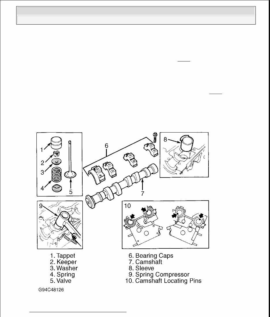
positioned. Install camshaft sprockets in relation to locating pins. See Fig. 2 .
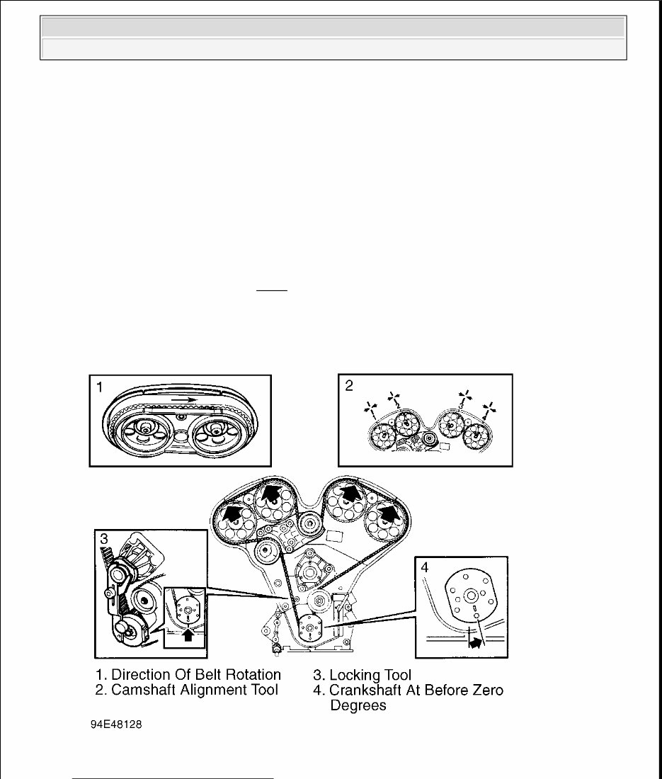
3. Install tensioning roller and upper adjusting roller. Install Locking Tool (KM-800-1) on No. 1 and No. 2
camshaft sprockets, and Locking Tool (KM-800-2) on No. 3 and No. 4 camshaft sprockets. Turn
crankshaft to just before zero degrees and install Locking Tool (KM-800-10) on crankshaft. Carefully
turn crankshaft in direction of engine rotation until arm is against water pump flange. Tighten arm.
4. Install timing belt. Install Belt Holder (KM-800-30) to hold timing belt in place. See Fig. 3 . Adjust
tensioning roller by hand to prevent belt from slipping out of cogs. Install crankcase ventilation housing
and oxygen sensor connector in its holder. Ensure "O" rings are in valve cover and wipe clean. To install
remaining components, reverse removal procedure.
Fig. 2: Removing Valve Train Components
Courtesy of SAAB-SCANIA OF AMERICA, INC.
2000 Saab 9-5
1999-2000 ENGINES 3.0L V6
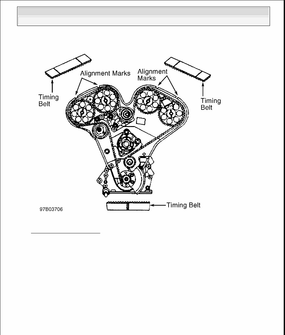
Fig. 3: Installing Timing Belt
Courtesy of SAAB-SCANIA OF AMERICA, INC.
FRONT CYLINDER HEAD
Removal
1. Disconnect negative battery cable. Raise and support vehicle. Remove 2 front exhaust pipe-to-exhaust
manifold bolts. Remove air shield. Drain coolant. Lower vehicle. Remove engine covers. Disconnect
cruise control cable. Disconnect throttle cable from bracket. Unclip control rod, detach bracket and move
it aside.
2. Disconnect hose clamps between inlet pipes and intake manifold, and between resonator and Mass
Airflow (MAF) sensor. Raise inlet pipes slightly. Disconnect all vacuum hoses and electrical connectors.
Mark hoses for reassembly reference. Remove pipes with resonator. Disconnect fuel lines and plug
connectors.
3. Remove intake manifold bolts. Remove throttle body preheater hoses, crankcase ventilation hose, and
vacuum hoses from intake manifold. Mark hoses for reassembly reference. Disconnect IAC valve
2000 Saab 9-5
1999-2000 ENGINES 3.0L V6

connector. Disconnect fuel pressure regulator hose. Remove wiring harness conduit under throttle body.
4. Disconnect Throttle Position Sensor (TPS) connector and ignition coil. Disconnect throttle body
connector and lift off intake manifold. Plug holes with paper.
5. Disconnect coolant manifold and move aside. Disconnect spark plug wires and ignition coil. Move coil
aside and disconnect ignition coil bracket.
6. Remove lifting eye and heat shield covering exhaust manifold. Disconnect resonator bracket and remove
secondary air injection pipe from exhaust manifold. Lift power steering servo oil reservoir. Disconnect
wire from torque arm engine mount. Remove torque arm. Remove servo line clamp from torque arm
engine mount. Remove engine mount. Disconnect upper hose from expansion tank and upper part of
generator air intake.
7. Slightly loosen crankshaft pulley bolts. Remove drive belt, belt tensioner, power steering pump pulley,
water pump pulley and cover. Remove crankshaft pulley, but do not remove center bolt. Put cylinder No.
1 at TDC of compression stroke. Camshaft sprocket, timing cover and crankshaft marks should be
aligned. Lock camshaft sprockets in place.
8. Mark timing belt direction of rotation. Remove timing belt. Turn crankshaft back 60 degrees BTDC.
Remove bracket securing upper adjusting pulley and tensioning pulley. Remove timing cover. Ensure "O"
rings are in place and do not fall into engine.
9. Remove cylinder head camshaft sprockets No. 3 and 4. Remove 2 timing cover bolts from cylinder head.
10. Loosen bolts one-half to one turn at a time and remove bearing caps on exhaust camshaft. Remove
camshaft seal and lift out camshaft. Loosen cylinder head bolts, one-half, then one-quarter turn, in order.
Lift off cylinder head. Use care not to bend valve stems. Remove intake manifold, valve depressors,
oxygen sensor holder, exhaust manifold and heat shield.
Installation
1. Position crankshaft at 60 degrees BTDC. Clean all contact surfaces and install head gasket. Ensure gasket
is installed with OBEN/TOP facing upward. Install exhaust manifold, tappets, heat shield and oxygen
sensor holder. Place cylinder head in position. Torque NEW bolts in order, to specification. See Fig. 1 .
See TORQUE SPECIFICATIONS table.
2. Install camshafts and lubricate with oil. Ensure locating pins are correctly positioned. See Fig. 2 . Note
markings on bearing caps and cylinder head. Install bearing caps and tighten bolts in order. Lubricate seal
lips and install gasket, camshaft bolt and washer. Install timing cover retaining screws in cylinder head.
3. Install Locking Tool (KM-800-1) on No. 1 and No. 2 camshaft sprockets, and Locking Tool (KM-800-2)
on No. 3 and No. 4 camshaft sprockets. Turn crankshaft to just before zero degrees and install locking
tool on crankshaft. Carefully turn crankshaft in direction of engine rotation until arm is against water
pump flange. Tighten arm.
4. Install timing belt. Install Belt Holder (KM-800-30) to hold timing belt in place. See Fig. 3 . Adjust
tensioning roller by hand to prevent belt from slipping out of cogs. Adjust belt counterclockwise. Install a
section of belt. Install Belt Tension Meter (83 94 985) to measure belt tension.
WARNING: Ensure wrench used to remove camshaft sprockets does not have
jaws that are too long. There is a risk of damaging casting, causing
tappet to jam.
2000 Saab 9-5
1999-2000 ENGINES 3.0L V6
5. Slightly tighten adjusting roller center bolts. Adjust lower adjusting roller counterclockwise to a belt
tension of 205-221 ft. lbs. (275-300 N.m). Belt turning torque should be 30 ft. lbs. (40 N.m).
6. Adjust tensioning pulley with an Allen wrench until 2 marks are aligned. Remove locking tool for
camshaft sprockets No. 1 and 2. Adjust upper adjusting roller until camshaft sprocket No. 2 moves .03-
.07" (1-2 mm) clockwise. Remove upper locking tool.
7. Rotate crankshaft over 2 revolutions until just before zero mark. Place locking tool on crankshaft.
Carefully turn crankshaft in direction of engine rotation until arm is against water pump flange. Tighten
arm. Install Camshaft Alignment Tool (KM-800-20) and ensure markings on camshaft sprockets are
aligned with markings on tool. See Fig. 4 . Check tensioning roller to ensure marks are in alignment.
8. Install timing cover. Ensure "O" rings are in place in valve cover and wipe clean. Install valve cover.
Install engine lifting hook and upper radiator hose. To complete installation, reverse removal procedure.
Fig. 4: Aligning Camshaft Sprockets
NOTE: Belt tension adjustment at this time is not final. Do not use this adjustment
as a check for final adjustment.
2000 Saab 9-5
1999-2000 ENGINES 3.0L V6

Courtesy of SAAB-SCANIA OF AMERICA, INC.
FRONT COVER OIL SEAL
Removal & Installation
1. Remove timing belt. See appropriate cylinder head removal and installation procedure. Install Holder (83
95 063) and remove crankshaft toothed belt sprocket and spacer ring. Remove seal, using care not to
damage crankshaft sealing surface.
2. To install seal , install inner section of Crankshaft Seal Assembly Tool (83 94 942) on crankshaft with
cone facing outward. Lubricate seal and install on shaft. Tap seal in place. Install spacer ring. Install
crankshaft sprocket. Tighten bolt to specification. See TORQUE SPECIFICATIONS .
OIL PAN
Removal & Installation
1. Disconnect negative battery cable. Raise and support vehicle. Remove splash shields for access to oil pan.
Drain engine oil. Remove oil pan mounting bolts and remove oil pan. See Fig. 5 .
2. To install, reverse removal procedures. Use NEW oil pan gasket. Tighten oil pan bolts to specification.
See TORQUE SPECIFICATIONS . Fill crankcase with engine oil.
OIL PAN HOUSING
Removal & Installation
1. Remove oil pan. See OIL PAN . Remove motor mount lower bolts/nuts from frame bracket. Remove oil
intake pipe. Remove A/C compressor hose support strap (if equipped). Remove oil pan housing bolts,
leaving corner bolts in place to hold oil pan housing in place.
2. Place matching marks on drive shaft for reassembly. Remove drive shaft bolts. Slide drive shaft rearward,
away from transmission, and secure aside. Remove catalytic converter hanger bolts. Lower vehicle.
3. Using an engine support from above engine, raise and support engine enough to remove oil pan housing.
Raise vehicle. Remove remaining oil pan housing bolts, and remove oil pan housing and gasket. See Fig.
5 . To install, reverse removal procedures. See TORQUE SPECIFICATIONS .
2000 Saab 9-5
1999-2000 ENGINES 3.0L V6
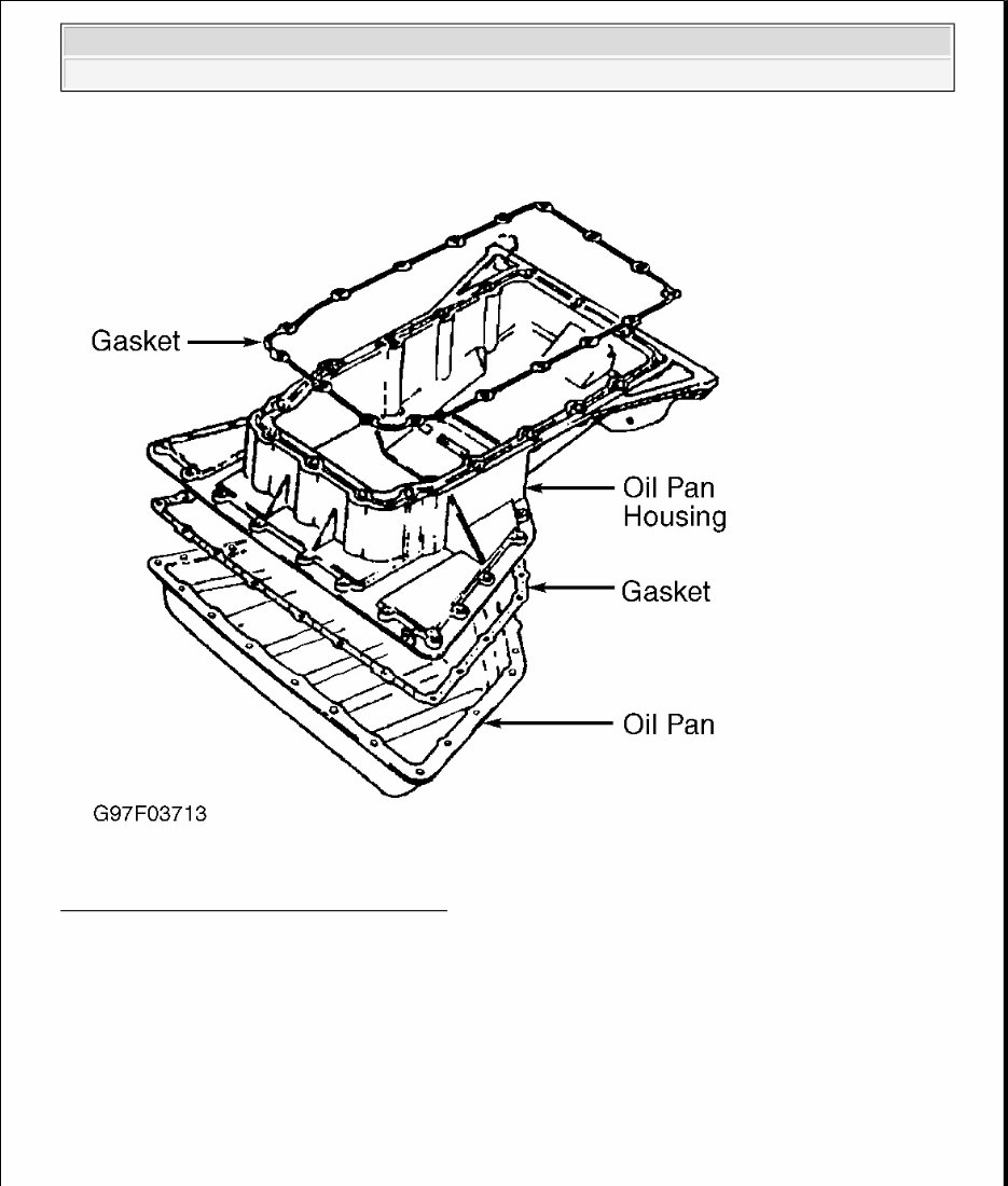
Fig. 5: Identifying Oil Pan & Oil Pan Housing
Courtesy of SAAB-SCANIA OF AMERICA, INC.
CAMSHAFT
REAR CRANKSHAFT OIL SEAL
Removal & Installation
1. Remove transmission. For M/T vehicles, see appropriate article in CLUTCHES. For A/T vehicles, see
NOTE: For camshaft removal and installation, see appropriate cylinder head removal
and installation procedure.
2000 Saab 9-5
1999-2000 ENGINES 3.0L V6
You're Reading a Preview
What's Included?
Fast Download Speeds
Offline Viewing
Access Contents & Bookmarks
Full Search Facility
Print one or all pages of your manual
$31.99
Viewed 77 Times Today


Secure transaction
What's Included?
Fast Download Speeds
Offline Viewing
Access Contents & Bookmarks
Full Search Facility
Print one or all pages of your manual
$31.99
- This complete factory service repair workshop manual is available for instant access on your computer, tablet, or smartphone.
- It covers all repairs, servicing, and troubleshooting procedures with detailed photos and diagrams.
- Professional mechanics and technicians use this manual, which contains step-by-step instructions and highly detailed exploded diagrams and pictures.
- You have the option to print out a single page or the entire manual.
- This manual can be used on multiple computers without any limitations or trial periods.
- There is no expiry date, renewal fee, or need to pay extra – you can use this manual for life.
- It is fully compatible with all Windows and MAC computers.
For more information, please click on the button.


