1977-1980 Rolls Royce Silver Shadow II Wraith II Corniche Camargue Bentley T2 Service & Repair Manual
What's Included?
Lifetime Access
Fast Download Speeds
Offline Viewing
Access Contents & Bookmarks
Full Search Facility
Print one or all pages of your manual
" " o c " c g N .. " Chapter A General information Section A 1 Identification A2 Precautions A3 Specification A4 Data A5 Body and Coachwork A6 Specia I procedures A7 Abbreviations. Symbols and Terminology AS Conversions
• u o "i " "0 @ Workshop Manua l Chapter A Section Page No. 1 2 3 4 5 6 7 8 9 10 11 I Al A2 I A3 I A4/ Chapter A Issue record sheet 1 December 1979 A5 I A6 The dates quoted below refer to the issue date of individual pages within this chapter. A7 I A8 I June 79 June 79 June 79June 79June 79 June 79June 79 June 79 June 79 June 79 June 79 June 79 June 79 June 79 June 79 June 79 Dec 79 Nov 79 June 79 June 79 June 79 June 79 Dec 79 Nov 79 June 79 June 79 June 79 Dec 79 June 79 June 79 June 79 12 _____________________________________________________________ __ 13 14 15 16 17 18 ______________________________________________________________ _ 19 20 21 22 23 24 _________________________________________________________________ _ 25 26 27 28 29 30 ___________________________________________________________ _ 31 32 33 34 35 36 ___________________________________________________________ _ 37 38 39 40 41 42 _____________________________________________________________ __ 43 44 45 46 47 48 ____ J-__ ____ .L_ __ _L __ __ _L__ ____ __ _L. ____ L_ __ __ __
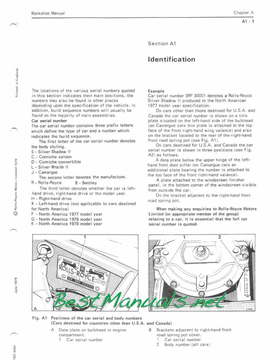
• " Workshop Manual The locations of the various serial numbers quoted in this section Indicates their main positions, the numbers may also be found in other places depending upon the specification of the vehicle. In addition, build sequence numbers will usually be found on the major ity of main assemblies. Car seria l number The car serial number contains three prefix letters which def i ne the type of car and a number which ind i cates the build sequence. The first letter of the car serial number denotes the body styling. S· Silver Shadow II C • Comiche saloon o • Corniche convertible l - Silver Wraith II J - Camargue The secono letter denotes the manufacture. R - Rotls-Royce B - Bentley The third letter denotes whether the car IS left- hand drive, right-hana drive or the model year. H - Right-hand drive X - leh-hand drive (not applicable to cars destined for North America) F - North Amer ica 1977 model year G - North Ame ri ca 1978 model year K - North America 1979 model year Fig. A1 Positions of the ca r serial and body numbers ChaPler A A1 • 1 Section A 1 Identification Example Car serial number SRF 30001 denotes a Rolls-Royce Silver Shadow 11 produced to the North American 1977 model year specification. On cars other than those destined for U.S.A . and Canada the car serial number is shown on a title plate situated on the left-hand side of the bulkhead (on Camargue cars this plate is attached to the top face of the front right-hand wing valance ) and also On the bracket located to the rear of the right-hand front road spring pot (see Fig. AI ). On cars destined for U.S.A. and Canada the car serial number is shown in three positions (see Fig. A2) as follows. . A data plate below the upper hinge of the left- hand front door pillar ( on Camargue cars an additional plate bearing the number is attached to the too face of the front riQht-hand valance \. A plate attached to the windscreen finisher panel. In the bottom corner of the windscreen visible from outside the car. On the bracket adjacent to the right-hand front road spring pot. When making any enqui r ies to R olls-Royce Motors limited (or appropriate member of the group) re l ating to a car, it is essent ial t ha t the fu ll car seria l number is quoted. (Cars destined fat count r ies other than U.S.A. and Canada) A Data plate on bulkhead in engine compartment. 1 Car serial number B Brackets adjacent to right -hand front road spring pot cover. 1 Car serial number 2 Body number \all cars )
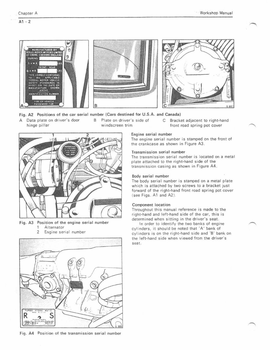
Chapter A Workshop Manual A1 -2 Fig. A2 Positions of the car serial number (Cars destined for U .S.A, and Canada) A Data plate on driver's door B Plate on drivers side of C Bracket adjacent to right-hand hinge pillar windscreen trim fr ont road spring pot cover Fig. A3 Position of the engine serial number 1 Alternator 2 Engine senal number Fig. A4 Position of the transmission serial number Engine serial number The engine serial number is stamped on the front of the crankcase as shown in Figure A3. Transmission serial number The transmission serial number is loca ted on a metal plate attached to the right-hand side of the transmission casing as shown in Figure A4. Body serial number The body serial number is stamped on a metal plate which is attached by two screws to a bracket just forward of the right-hand front road spring pot cover (see Figs. A1 and A2 ). Component location Throughout this manual reference is made to the right-hand and left-hand side of ihe car, this is determined when sitting in the drivers seat. In order to identify the two banks of engine cyl inders, it should be noted that' A' bank of cylinders is on the right-hand side and '8' bank on the left-hand side when viewed from the drivers seat.
• , • ! • Worksnop I A The items in this section identified A6 with the hydraulic system mineral oil symbol relate to Corniche and Camargue cars from serial number 50 001 . These cars use hydraulic system mineral oil in the hydraulic systems. The in formation contained within this section highlights important notes, warnings and precautions listed elsewhere in this manual. This section should be used as a quick reference guide to any features considered essential for the safety of either the operator or the vehicle . The li st is not exhaustive. In the interests of health and hygiene. items norma ll y used in service workshops such as anti- freeze, brake fluid. lubrican t s. adhesi ves, cleaning agents, etc., should all be treated with extreme caution. As these items can be of a toxic nature they must not be swallowed and contact with the skin must be kepI to an absolute minimum. Towing the vehi cl e Before towing the vehicle note the following. l a) Do not tow the vehicle to start the engine. (b) Do not tow the vehi cle if any mechanica l damage to the transmI ss ion is suspected. tc) Do not tow the vehicle with a low fluid level in the torque convener transmission. Should it be necessary to tow the vehicle for even a short dis tance a solid tow bar must be used. A speed of 72 k.p .h . t 45 m.p.h. ) and a maximum distance of 80 kilometres (50 miles ) must not be exceeded. For towing distances in excess of 80 kilometres (50 miles) ei t her disconMct the propeller shaft or transport the car. Alwa ys t ow the vehicle wi th the torque converter transmi ssion in 'Neutral'. Metric components A small number of the nu ts, bolt s and set screws used in the manufacture of these cars are di mensi oned to the 'Iletr ic syst em. it is important therefor e, that when new pa n s become necessa ry the cOl'Tect rep lacement S are obta ined and fitt ed. Chapter B - Spe cial proc es ses Re-c ommiss ioning after stor age Always ..,nS,JlfJ th(l l t!,,! IS removed irom the car before chargillfl . Chapte r A Sectio n A2 Precautions Chapter C - Air conditioning Danger - Exhaust gas es A2· , Sitt ing in the car in a confined space with the engine running is dangerous. Operating the air condit ioning un i t will increase this danger. First aid - Refriger a nt burn s If th.e skin is injured by refrigerant it should be bathed with cold water and treated in a simi l ar manner to frostbite. An eye injured by refrigerant must be immediately washed with clean cold water. The eye must not be rubbed as this will aggravate the injury . A doctor should be consulted as soon as po ssible after adm inistering this emergency treatment. Chapter F - Propeller shaft and Universal joints Propell er shaft - To remove The crossmember centre section must not be allowed to hang on the parking brake cables. Chapter G - Hydraulics It is of the utmost importance that Servi ce Personnel should fully appreciale that the hydrauliC systems operate at high pressures. The systems are designed to oper ate sa f ely under normal working conditi ons, but. when work is performed on the systems, certain precautions must be observed to ensure adequate safety to personnel and equipment. C lean I in ess To ensure correct functioni ng of the hydraul ic systems it is imper ative thaI metic ul ous care is taken to ensure complete c leanl iness at a ll t imes. Operation of the bra kes (en gine not running) The service brakes (i.e. foot brake) consist of two independent all power systems. The power for these systems in the form of hydrau l iC pressure is pr ovided by two engine driven hydraul ic pumps. When the engine stops, a limited reserve of pressure remains stored in the hydraulic accumul ators. Due to brake operation. nalural internal leakage and height
Chapter A control system operation this energy will be slowly depleted. Although a number of brake applications will be available immediately after the engine stops, it is recommended that the service brakes are not utilised when the engine is not running. Prior to towing the vehicle reference should be made to the relevent section in this chapter. Precautions before working on the car Before any work, except bleeding and specified tests, is carried out on the car hydraulics, the systems must be depressurised (refer to Section AS or Chapter G). With the exception of bleed screws, components must never be disturbed when Ihe systems are in a pressurised state. Part 1 • Cars prior to car serial number 50 001 RR 363 Brake fluid Always refer to Chapter 0 - lubricants, for the correct type of fluid to use in the system. Brake fluid is hygroscopic (i.e. that the fluid will absorb and chemically combine with water from the atmosphere). Brake fluid which is contaminated by water will boil at a much lower temperature. If the fluid is contaminated by water and the car is braked excessively or very hard from high speeds, there will be a tendency for the heat generated by the brakes to boil the fluid, finatly resulting in vaporisation of the brake fluid and ineffective brakes. To eliminate possible contamination of the brake fluid it is essential that the fluid is not exposed to the atmosphere for more than the absolute minimum of time. It should always be stored in and used direct from small sealed containers and when the systems are replenished, the two reservoir covers and the container cover must be replaced immediately. Hydraulic accumulator spheres The hydraulic accumulator spheres are charged on one side of the diaphragm with nitrogen gas through a one-way charging valve in the end of the sphere. Replacement spheres are supplied in an uncharged state and therefore must be charged by the Franchise holder before they are used to replace faulty spheres. Exchange spheres are supplied complete with a charging valve cap; a warning plate and locking washer are supplied loose. A label is attached which reads 'Uncharged • Remove label on charging and attach warning plate'. It is of the utmost importance that, when the sphere is charged, the warning plate is fitted below the charging valve cap. Spheres must never be transported in a charged state. If spheres are to be returned to the Parts Department at Crewe, or transported by rail, air or sea, they must be discharged before despatch. Workshop Manual Service personnel are advised that spare accumulator spheres should be charged and leak tested immediately on receipt and then stored in a charged condition. This ensures that the storage period is utilised as a tim?/leakage test so that when a sphere is removed from store and the pressure of the nitrogen is tested after fi tting, it can be seen whether the sphere is still fully charged with nitrogen. Spheres which have been correctly charged and successfully leak tested before storage and which then show a loss of pressure in excess of 1,75 kgf/sq.cm. (25 Ibflsq.in. ) when tested prior to fitting, must be rejected. The sphere should be recharged and leak tested again to determine the cause of leakage. If the leak persists, the sphere should be discharged and dismantled, the diaphragm checked and renewed if necessary. The displaced components should be returned to the Parts Depart· ment at Crewe, with all relevant information. Storage and transportation To avoid contamination, it is of the utmost importance that AR 363 brake fluid and hydraulic system mineral oil containers and components are kept completely separate. Conventional brake fluids have a detrimental effect on rubber seals and hoses used in a mineral oil system. Replacement parts, pipes and units must be correctly and securely sealed with the recommended blanks which must not be removed unt; I immediately prior to fitting. They must also be adequately protected from dust or damage. Sealing rings and rubber pipes in store should be protected from dust, light and heat. Part II - Cars from car serial number 50 001 Hydraulic System Mineral Oil Always refer to Chapter 0 • lubricants, for the correct type of approved hydraulic system mineral oil to use in the system. Under no circumstances should a conventional synthetic brake fluid be substituted f()C" the genuine hydraulic system mineral oi I. To avoid contamination, all mineral oil containers and components should be stored in a clearly defined area away from that used for conventional brake fluid. Mineral oil is not hygroscopic ( i.e. it will not actively encourage water to enter the system via the hoses and seals ) this eliminates the possibility of vapour lock fade, but more important it further reduces internal corrosion on components. Brake pumps The hydraulic system mineral oil brake pump differs
• , • Workshop Manual from the brake fluid type and no attempt should be made to interchange the parts etc .. for further information refer to Chapter G, Section 6m. Component identificat ion All components which are susceptible to damage from brake fluid are co lour coded green and have a GMF prefix part number e.g. GMF 1062. Other components which are not susceptible to brake fluid damage ( i.e. metal pipes and connectors) are not colour coded and do not have a GMF prefix part number. It must be stressed however that these parts must not become co ntaminated with brake fluid, as this fl uid could circul ate to other components in the hydraul ic systems. Hydraulic accumulator and gas spring spheres The accumulator and gas spring spheres are charged on one side of their diaphragms with nitrogen gas prior to despatch from the factory. Each sphere is marked with a band of white paint or a yellow stick.an label when charged. The charge pressure in 'bars ' (i.e. 1 bar:14.5 Ibf/s q .i n.) is stamped on the non·return va l ve cap at the lower end of the sphere. It is recommended that spheres are stored and issued from stock in date sequence. Storage and transportation To avoid contamination, it is of the utmost importance that AA 363 brake f lu id and hydraulic system mineral oil containers and components are kept completely separate. Conventional brake fluids have a detrimental effect on rubber seals and hoses used in a mineral oil system. Chapter H • Sub·frames and suspension Urethane foam fi lied components The suspens ion crossmember and f inal drive cross- are filted with uretha ne foam. When using c utting or we ldi ng equipment on the crossmembers suitable preca utions should be taken not to inhale the t oxic gases given off when the temperature exceeds 200· C. ( 392"'F. ). Shock dampers Each shock dam per contains nitrogen gas under pressure. On no acCOunt shoul d the damper be subjected to undue for ce of any description. Do not clamp the damper in a vice. If the spring support has seiZed onto the damper, renew the shock damper and spring support. To render a shock damper safe for d is posa l, drill a small hole 25.40 mm. (1 .0 in.) from the closed end of the outer tube. The escaping gas should not be allowed to come into contact with eyes or skin whilst under pressure. Immediately the hole has been drilled. stand clear and allow the mtrogen gas to disperse to atmosphere. Chapter A A2 - 3 Front r oa d springs Use of the r..:>ad spring retaining tool ( AH 8809) should be restricted to a maximum of 200 appl i cations. Inspecti on of the long bolt threads must be made at frequent intervals. The person lifting the compressed assembly out of the car must keep their head and body clear of the tool. Caster and Camber angles Th e caster and camber angles must always be checked at the same time, as adjustment of one affects the other. 'Jacking up' the car Care must be taken not to leave the car jacked up for long periods without support to the trailing arms, otherwise damage may result to the trailing arm mounting points or height cont ro l ball pin brackets (see also Page A6· 2) . When using a hydraulic jack to ra ise the car ensure that a hardwood block is placed between the jack and the undemeath of the car. The eng ine fr ont pull ey should not. be used to support the engine. Warning Cars from car seri al number 50 001 Rear Suspension Before any work is ca rried out on the r ea r suspension frame tubes etc .. reference must be made to the appropriate section in the Workshop Manual. Chapter K - Fuel system Fue l - To drain The fuel is highly inflammable and extreme care must be exer cised whenever the system is opened (i.e. pipes disconnected) or when the fuel is drained. The following basic T\Jles should app ly. 1. Disconnect the battery leads. 2. Place 'No Smoking' signs in the vicin i ty of the vehicle. 3. Place a C02 Fire Extinguisher (or other suitab le equivalent) in the vicinity of the vehicl e. 4. Safety goggles shou ld be wom at all times by the operator. S. If fue l is to be drained from the tank, it should be syphoned into a suitable covered container. 6. When draining the fuel system on cars fitted with catalytic converters it is most important that the fuel system is not completely drained by runni ng the engine. otherwise damage to the catalytic conven er w il l result. Carburetters SUo HIF7 carburetters are set and balanced by
Chapter A accurate flow measuring techniQues during manufacture and therefore, adjustment of the mixture screws shou ld not be necessary. su. carburetters • To dismantle Dismantling of the components within the carburetters is not re commended as a ll carburetters are set and balanced by accurate flow measuring techniques during manufacture. SU carburetters • To inspect Wh en cleaning the inside of the suction chamber and piston rod guide use either fuel or methylated spirit (denatured alcohol) and wipe dry. Abrasives must not be used. Chapter L - Cooling system Cooling system· To flush Under no circumstances use a strong alkaline compound or detergent to clean the cooling system. Such compounds have a detrimental chemical action on aluminium alloys. Thermostat - To test Important If the water is heated too qu i ck ly, or if the c irculation is poor, a false readi ng may result. The thermostat has its opening temperature stamped on the base of the unit, e.g. [SO·C. (l90-Fj When fully open, the va lve should have travelled a minimum of 9,5 1Tm . (0.375 in .). Chapter M - Electrical system It is imponant that no 'live' cOfl nectioos or disconnections are made where fuel, fuel vapour or other inflammable materials are present. The battery must not be coonected or dis- connected whi:st the engine is ru nning. Tile engine must be switched off before attempting to disconnect a lead from the charging syst em . Always check for correct polarity before fitting a battery. Whene ve r a lead is dis connected, it should be identified in relation to its terminal!o faci li tate reconnection. Short circuiting or reverse polari ty no matter how br ief, will cause immediate and pennanent damage to transistors and diodes. Radio i nterf erence suppressors are f itted to the 'A' terminal of the regulator and to the 'A' and .... tenninal of the alternator. Do not connect suppressors to the 'F' terminal (brown/ green lead ). Battery It is imperative that the negative (eanh) lead is disconnected from the battery before comm:!ncing work on the electrical system or components, or if any electri c arc welding is to be used on the car. Workshop Manual The battery must not be disconnected Of connected whilst tne alternator is running nor connected into the system without first checkIng correct polarity. Battery - To charge The gases given off during charging are highly inflammable. Always remove tne banery from the car before charging. Chapter N • Steering system Rack and pinion unit Do not st rike this unit with a hammer as e>etreme damage could result. Belt tension A Slipping belt will squeal and produce judder at the steeri ng wheel n earing full lock. Belt dressing must not be applied to prevent slip. Steering pomp ' Priming and filling When filling an empty system with t he engi ne running, it is essential that at no time the fluid level in the pump reservoir be allowed to drop sufficiently for air to be drawn in to the system. If this occurs, Irreparable damage to the pump will res ult . Chapter R • Wheels and tyres Tyre to fit Dunlop tyre bead lub ricant TBLl or T8L2 is recommended for use when fitting va l ves and tyres. It is most important that soap or other similar agents are not used. Tyre service Periodicall y the balance of each wheel should be checked and corrected if necessary. With the exception of steel braced radial-ply ty res, wheels should not be interchanged to give even tyre wear, For full information refer to Chapter R, Under no circumstances shou ld any tyres be fitted whi ch have been branded 'Regraded Quali ty', 'Remould Qual ity' or 'Seconds', or those which have had the speed rating removed or altered. Care of tyres Clean any oil or grease from the tyres using a soap solution and water, then rinse off with clean water. Always remove any oi l spi llage from the tyres imme diately as certain oils , in par tic ular hydraulic system mineral oi l, have a hannful effect on the lyre rubber if not cleaned off immediately. Chapter T - Transmission Remote gearchange selector contacts Whenever the moving or fixed contacts have been
• , 1l , < • • • Workshop Manual disturbed or after the remote gearchange selector has been dismantled and assembled always test the assembly. Torque converter transmission· To remove When removing the transmission from the car always use the retaining clamp AH 7952 (J - 21366), other- wise the converter may fall as the transmission is withdrawn. Chapter U • Emission control systems Australia. Canada. Japan and U .S. A. Exhaust emissioo control system The exhaust emission control system is designed to reduce the carbon monoxide, unburnt hydrocarbon and oxides of nitrogen content in the exhaust gases. The system does not eliminate the danger caused by inhaling exhaust gases in a confined area. Before commencing work on the exhaust emission control system, care should be taken to ensure that the relevant components are not hot. Unleaded fuel (Canada. Japan and U.S.A.) Use the correct grade of unleaded fuel ooly. The use of leaded fuel wi ll result in a substantial reduction in the perionnance of the catalyst. Under no circumstances add fuel system cleaning agents to either the fuel tank or carburetters for induction into the engine. as these materials may have a detrimental effect on the catalytic converter. 00 not allow the vehicle to run out of fuel. If the vehicle does run out of fuel at a high speed. possible damage to the catalyst could result. Chapter A A2·5
Workshop Manual A The items in ttlis section identified with the hydraulic system mineral oil symbol relate to Corniche and Camargue cars from serial number 50 001. These cars use hydraulic system mineral oil in the hydraulic systems. Braking system Brake fluid Cars prior to car serial number 50 001 Castrol RR363 brake fluid . This fluid exceeds current S.A.E. J 1703 specifications in many respects and complies with D.O.T. 3 grade of FMVSS 116. Hydraulic system mineral oit Cars from car serial number 50 001 Castrol hydraulic system mineral oil Refer to Chapter D - Lubricants, for al t ernatives. Maximum operating pressure (pump cut-out pressure ) 175,77 kgf/sQ.cm. (2500 lbf/sQ.in.) Pump cuHn pressure 126,55 kgflsq.cm. (1 800 lbf/sq.in. ) Caliper type Front - Four M 16 calipers Rear - Two T11 / '1 calipers Brake pads Service (power ) - Mintex V 1431 Parking brake - Mintex M 68 Pad area Service brake Front - 298,4 sq.cm. (46.25 sq.in. ) Rear - 237,93 sq.cm. (36.88 sq.in. ) Parking brake - 41,03 sq.cm. (6.36 sq. in. ) Swept area Front - 1464.51 sq.cm. (227.0 sq . in. ) Rear - 1 603,87 sq.cm. 1248.6 sq.in. ) Total - 3 068.38 sq.cm . 1475.6 sQ.in. ) Disc diameter 27,94 cm. ( 11 in. ) Nominal 28,1 cm. (11.06 in. ) - front 27.7 cm . (10.9 in. ) - rear } Actual Section A3 Specification Disc width Front vent il ated - 3,18 cm. ( 1.250 in .) Rear - 1,27 cm . ( O.SOO in. ) Chapter A A3 - 1 Capacities Metric Imperial U.S. Brake and height control system -RR 363 brake fluid 2,5SlitTes 4Y.! pt. SYlpt. Hydraulic system mineral oil 4.0litres 7pt. Cooling system Drive-shaft ball and trunnion joint 16litres 28Ylpt. (each ) 150 C.c. Engine oil sump Without changing filter When changing oil filter Final drive unit Fuel tank 8.4 l itres 9,4 Htres 16Y2pt. 2,55litres 4%Pt. Cars prior to car serial number 50 001 Cars destined for 8Yl pt. 3414pt. lOpt. 5Y.!pt. U.S.A . ; tnd Canada 85 litres 22%9al. Cars other than thos e destined for U.S.A. and Canada 107 titres 2Jlhgal. 28gal. Cars from car serial number 50 001 108 litres gal. 28Yl gal. Steering system 0.74 titres 1 Torque converter Transmission ( dry ) 10.6litres 18' 1, pt . 22Yi:pt. When changing fluid in sump only 2,8 litres 5 pt . 6 pt. When changing fluid in sump and renewing intake s trainer 4,5 titres 8 pt. 9Yl pt.
Thank you for considering this comprehensive Workshop Service Repair Manual.
This manual is an invaluable resource for both professional mechanics and DIY enthusiasts, covering every service and repair procedure for the Rolls Royce Silver Shadow II, Wraith II, Corniche, Camargue, and Bentley T2 models from 1977 to 1980.
DESCRIPTION:
Save a significant amount of money by performing your own repairs with this easy-to-follow manual. It includes step-by-step instructions and detailed illustrations for all servicing and repairs. Once downloaded, the manual is yours to keep forever. You can print individual pages, chapters, or the entire manual, and it can also be saved to your tablet or smartphone.
MODELS COVERED:
All Models/Engines/Trim/Transmissions Types Are Covered
CONTENTS:
This high-quality manual covers all repair procedures from A to Z, ensuring that every repair and service procedure is included.
COMPUTER REQUIREMENTS:
This manual is compatible with all PC and MAC computers, tablets, and mobile phones. The only software required is Adobe Reader, which is typically pre-installed on your computer or can be downloaded for free.
INSTANT DELIVERY:
Upon payment confirmation via Visa, MasterCard, or PayPal, the manual will be instantly emailed to the address provided during checkout.
Customer Satisfaction Guaranteed.
Recently Viewed
5,521,897Happy Clients
2,594,462eManuals
1,120,453Trusted Sellers
15Years in Business
Price:
Actual Price:
1977-1980 Rolls Royce Silver Shadow II Wraith II Corniche Camargue Bentley T2 Service & Repair Manual