1995-2002 Renault Megane I Service & Repair Manual
What's Included?
Lifetime Access
Fast Download Speeds
Offline Viewing
Access Contents & Bookmarks
Full Search Facility
Print one or all pages of your manual
77 11 176 201 APRIL 1995 Edition Anglaise General "The repair methods given by the manufacturer in this document are based on the technical specifications current when it was prepared. The methods may be modified as a result of changes introduced by the manufacturer in the production of the various component units and accessories from which his vehicles are constructed." All copyrights reserved by the Regie Nationale des Usines Renault. Copying or translating, in part or in full, of this document or use of the service part reference numbering system is forbidden without the prior written authority of the Regie Nationale des Usines Renault. Régie Nationale des Usines Renault S.A. 1995 SPECIFICATIONS LIFTING TOWING LUBRICANTS CONSUMABLES DRAINING, RE-FILLING BA0A - BA0E - BA0F - BA0G - BA0L - BA0U C VALUES AND SETTINGS
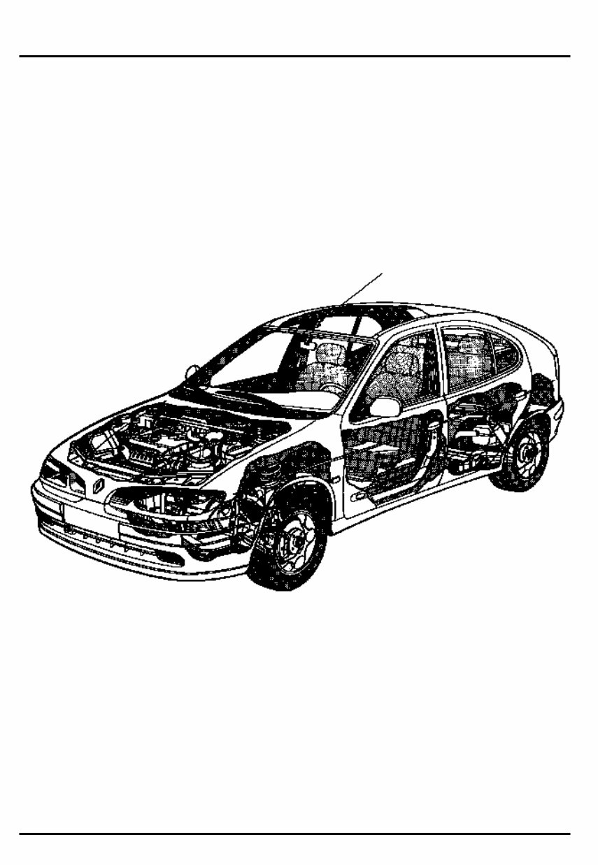
SECTION VIEW
TOWING All types Contents SPECIFICATIONS Engine - Clutch - Gearbox Vehicle identification 01-1 01-2 LIFTING Trolley jack - Axle stands Vehicle lifts Page 01 02 03 General 02-1 02-2 03-1 LUBRICANTS - CONSUMABLES Packaging 04-1 DRAINING, RE-FILLING Engine Gearbox Power assisted steering 04 05 05-1 05-3 05-4 VALUES AND SETTINGS Dimensions Capacity - Grades Belt tension Accessories belt tension Timing belt tension Tightening the cylinder head Dimensions of the main braking components Values for checking the front axle geometry Values for checking the rear axle geometry Underbody heights Brake limiter 07 07-1 07-2 07-5 07-7 07-13 07-15 07-17 07-18 07-21 07-22 07-23
SPECIFICATIONS Engine- Clutch - Gearbox 01 Vehicle type Engine Type Capacity Clutch type Type of manual gearbox and automatic transmission BA0E E7J 1390 180 DST 3050 180 CP 3300 JB1 BA0F BA0L K7M 1598 200 HR 4000 JB1 BA0G F3R 1998 215 HRN 4000 JB3 BA0A BA0U F8Q 1870 200 HRV 4600 200 HRV 3100 JB1 BA0F K7M 1598 - AD4 VEHICLE IDENTIFICATION Example : BA0E B : Body type (example 5 door hatchback) A : Project code (example 64) 0E : Engine suffix (example E7J 764) 01-1
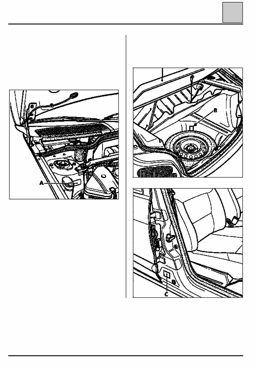
SPECIFICATIONS Vehicle identification • near to the emergency spare wheel (B) with a duplicate label of the oval plate on the lower section of the passenger door (C). 01 LOCATION OF THE VEHICLE IDENTIFICATION PLATE Two possible locations on the vehicle: • in the engine compartment (A), 98485-1R 98517R 98516R 01-2
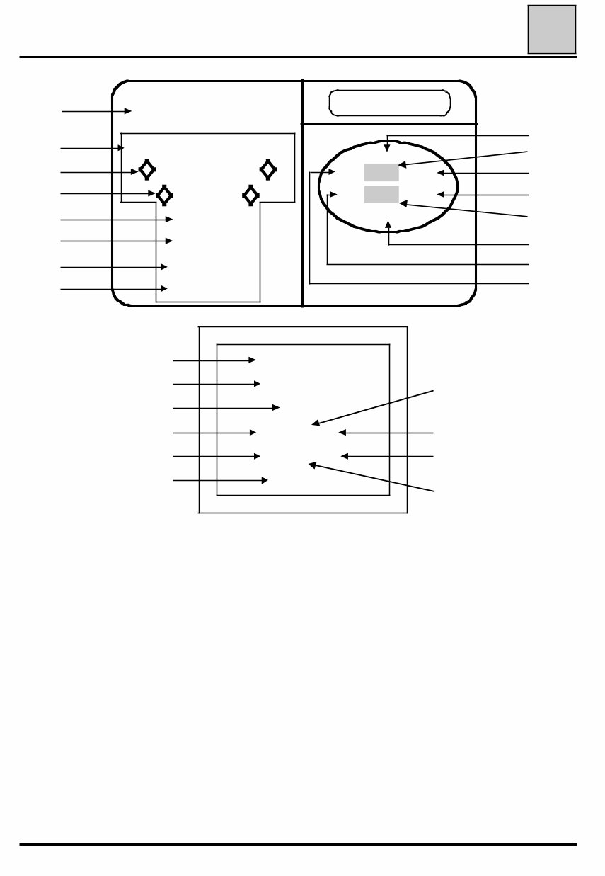
SPECIFICATIONS Vehicle identification 01 REGIE NATIONALE DES USINES RENAULT S.A. e000-00/00000-0000-00 VF0000000 00000000 0000 kg 0000 kg 1 - 0000 kg 2 - 0000 kg 10 0 0 0 0 0 0 0 0 0 0 0 0 0 0 0 0 0 0 0 11 0 0 0 0 0 0 0 0 7 13 8 14 9 12 Renault 1 2 3 4 5 6 VF0000000 00000000 0000 00 000 000 00 000 000 0000000 9 10 12 11 1 2 8 7 14 13 B A 01-3
SPECIFICATIONS Vehicle identification 01 It shows: At A : the name of the manufacturer, At B : the E.E.C. approval number At 1 : the type mines of the vehicle preceded by the world manufacturers identification code (VF1 corre- sponds to RENAULT FRANCE), At 2 : the chassis number, At 3 : the maximum permissible weight, At 4 : the maximum permitted total train weight, At 5 : the maximum permitted weight on the front axle, At 6 : the maximum permitted weight on the rear axle, At 7 : the first figure indicates the gearbox or factory options, the second figure indicates the equipment level, At 8 : the vehicle type, At 9 : the technical equipment code, At 10 : additional factory optional equipment, At 11 : the equipment level, At 12 : the paint code, At 13 : a letter describing the factory of manufacture followed by the fabrication number, At 14 : the trim code. NOTE : Depending on the country of export, certain details might not be given. The plate described above shows all possible information. ALLOCATION OF TECHNICAL EQUIPMENT CODES The equipment code, the three letters which appear in (9), must be documented for vehicle identification reasons (ordering spare parts, warranty claim, etc.) 01-4
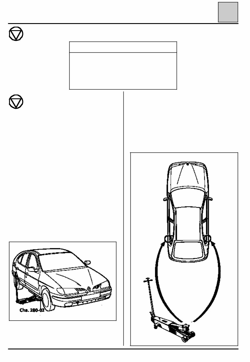
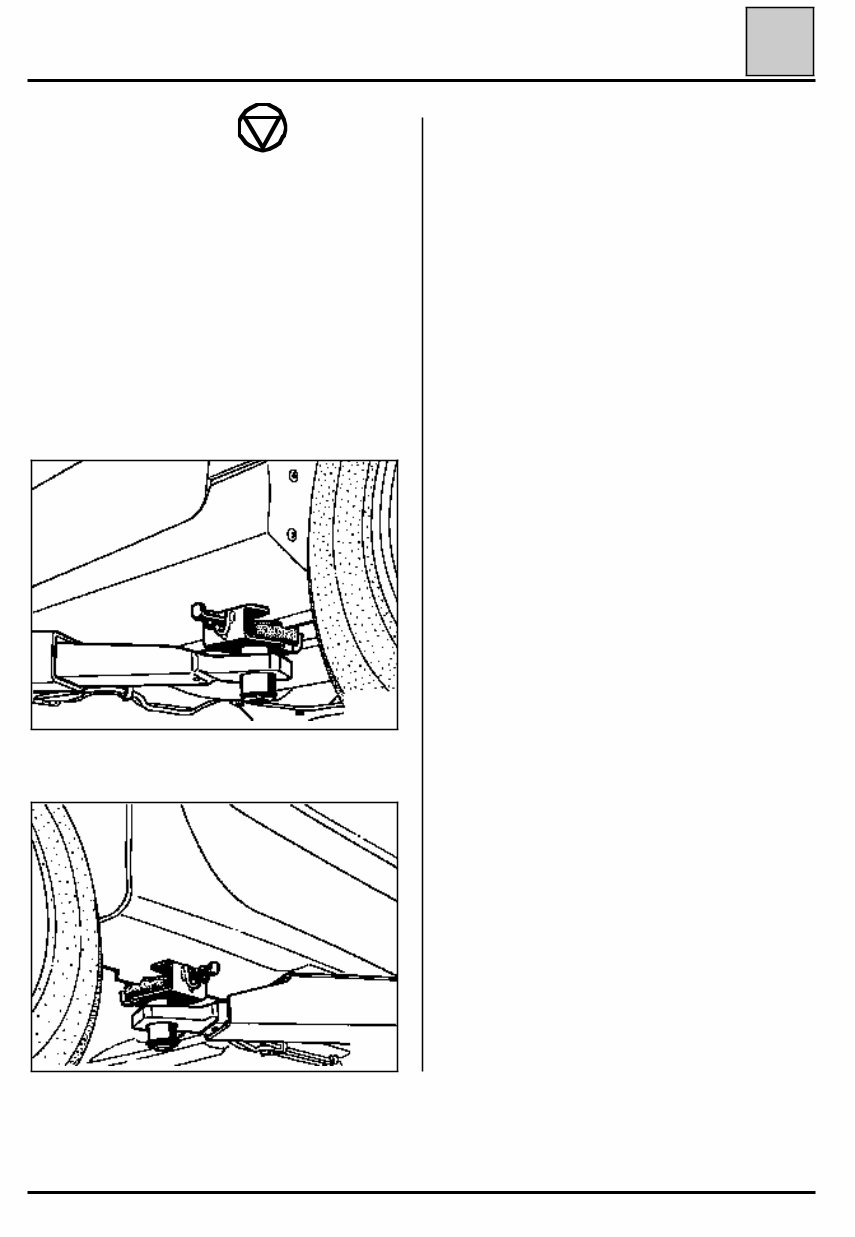
LIFTING Trolley jack - Axle stands AXLE STANDS When putting the vehicle on axle stands, they must be positioned: - either under the reinforcements designed for lifting the vehicle using the vehicle’s jack, - or under the points located behind the reinforcements. Axle stands are positioned at the rear when the vehicle is lifted from the side. 02 98699R Safety symbol (special precautions to be taken when carrying out operations). SPECIAL TOOLING REQUIRED Cha. 280 -02 Adaptable cross piece for trolley jack Cha. 408 -01 or Adaptable socket for trolley jack Cha. 408 -02 If a trolley jack is used, appropriate axle stands must always be used. It is forbidden to lift the vehicle by supporting its weight under the front suspension arm or under the V shaped part of the rear axle. Depending on the type of trolley jack, use sockets Cha. 408-01 or Cha. 408-02 to position the cross piece Cha. 280-02. To lift the front or rear, support the vehicle’s weight under the vehicle’s jacking points . TROLLEY JACK USED FROM THE SIDE Use cross piece Cha. 280-02. Take the weight under the sill, level with the front door. Position the flange correctly in the groove of the cross piece. 98336G 85679-1G7 02-1
LIFTING Vehicle lifts 02 SAFETY INSTRUCTIONS Several scenarios should be considered: 1 - WHEN REMOVING COMPONENTS In general, never use a 2 post lift , if a four post lift can be used. If this is not possible, position the lifting pads under the body sill, level with the vehicle’s jacking points. 2 - SPECIAL CASE - REMOVING AND REFITTING THE ENGINE AND TRANSMISSION ASSEMBLY In this special case, the body of the vehicle must be firmly attached to the arms of the two post lift using the special pads. FOG Reference FOG 449 8111 - 449 8411 or CHEMICO Reference 39 2550 0001 or SCHENCH Reference 776 684 98703S FRONT 98704S REAR These must be positioned in line with the vehicle’s jacking points. They must be clipped into the holes in the body sill. 02-2
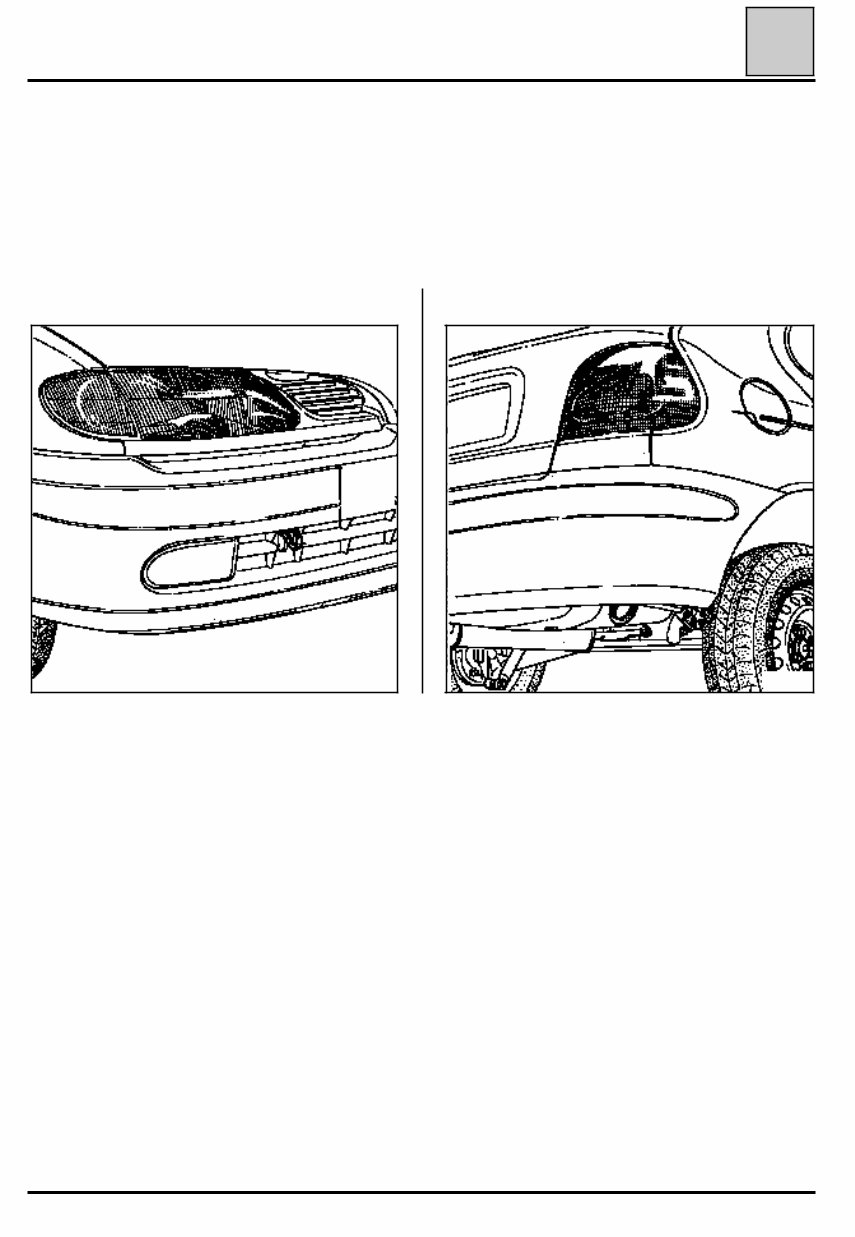
TOWING All types FRONT 03 OBSERVE THE LEGAL TOWING REQUIREMENTS OF THE COUNTRY YOU ARE IN. NEVER USE THE DRIVESHAFTS FOR TOWING THE VEHICLE. The towing points may only be used for towing the vehicle on the road. They should never be used for remo- ving the vehicle from a ditch or for any other similar breakdown operation or to lift the vehicle, either direct- ly or indirectly. 98705S REAR 98702S 03-1
The Renault Megane I 1995-2002 Service Repair Manual is a comprehensive guide that provides detailed instructions and procedures for maintaining and repairing the Renault Megane I models from 1995 to 2002.
Whether you are a professional mechanic or a passionate DIYer, this service manual is an invaluable resource for you. It covers various aspects of the vehicle, including engine, transmission, suspension, brakes, electrical systems, and more.
With step-by-step instructions and illustrations, this manual helps you understand the inner workings of your Renault Megane I and enables you to perform repairs and maintenance tasks with confidence. It also includes troubleshooting tips and diagnostic procedures to help you identify and resolve issues efficiently.
This service repair manual is specifically designed for the following Renault Megane I models:
Renault Megane I Hatchback 1995-2002
Renault Megane I Coupe 1995-2002
Renault Megane I Cabriolet 1995-2002
Renault Megane I Estate 1995-2002
Whether you need to replace a worn-out part, perform regular maintenance, or tackle a complex repair, the Renault Megane I 1995-2002 Service Repair Manual is your trusted companion. Get your hands on this comprehensive manual today and keep your Renault Megane I in top-notch condition for years to come.
Recently Viewed
5,521,897Happy Clients
2,594,462eManuals
1,120,453Trusted Sellers
15Years in Business
Price:
Actual Price:
1995-2002 Renault Megane I Service & Repair Manual