AIR SUSPENSION Fault finding - Introduction 38F - 2 38F V3 MR-379-X70-38F000$124_eng.mif MASTER Phase 1 and 2 138F AIR SUSPENSION Fault finding - Introduction 1. SCOPE OF THIS DOCUMENT This document presents the fault finding procedure applicable to all computers with the following specifications: 2. PREREQUISITES FOR FAULT FINDING Documentation type Fault finding procedures (this manual): – Assisted fault finding (integrated into the diagnostic tool), Dialogys. Wiring Diagram – Visu-Schéma (CD-ROM), paper. Type of diagnostic tools – CLIP Special tooling required 3. RECAP To run fault finding on the vehicle's computers, switch on the ignition in fault finding mode (+ after ignition feed). Vehicle: Master phases 1 and 2 Function concerned: Controlled suspension Special tooling required Multimeter SUS_V04_PRELI Suspension pneumatique - X70ph2 v2.0 MR-379-X70-38F000$124_eng.mif
AIR SUSPENSION Fault finding - Introduction 38F 38F - 3 V3 MR-379-X70-38F000$124_eng.mif MASTER Phase 1 and 2 Faults Faults are classed as either present or stored (having appeared in a certain situation and then disappeared, or being still present but not diagnosed in the current situation). The present or stored status of faults should be taken into consideration when the diagnostic tool is switched on after the + after ignition feed (without any system components being active). Present faults must be dealt with according to the procedure specified in the Interpretation of faults section. For stored faults, note the faults displayed and follow the instructions in the Notes section. If the fault is confirmed when the notes are applied, the fault is present. In this case, deal with the fault. If the fault is not confirmed, carry out some basic checks. Check: – The electrical lines on which there is a fault; – The connectors on these lines (corrosion, bent pins, etc.); – The resistance of the faulty component; – The condition of the wires (insulation melted or split, chafing, etc.). Conformity check The aim of the conformity check is to check statuses and parameters that do not produce a fault display on the diagnostic tool when they are inconsistent. Therefore, this stage is used to: – carry out fault finding on faults that do not have a fault display, and which may correspond to a customer complaint. – check that the system is operating correctly and that there is no risk of a fault recurring after repairs. This section features the fault finding procedures for statuses and parameters, and the conditions for checking them. If a status is not behaving normally or a parameter is outside the permitted tolerance values, consult the corresponding fault finding page. Customer complaints - Fault finding chart If the check using the diagnostic tool is satisfactory but the customer complaint is still present, the fault should be treated as a customer complaint. A summary of the overall procedure to follow is provided on the following page in the form of a flow chart. Suspension pneumatique - X70ph2 v2.0
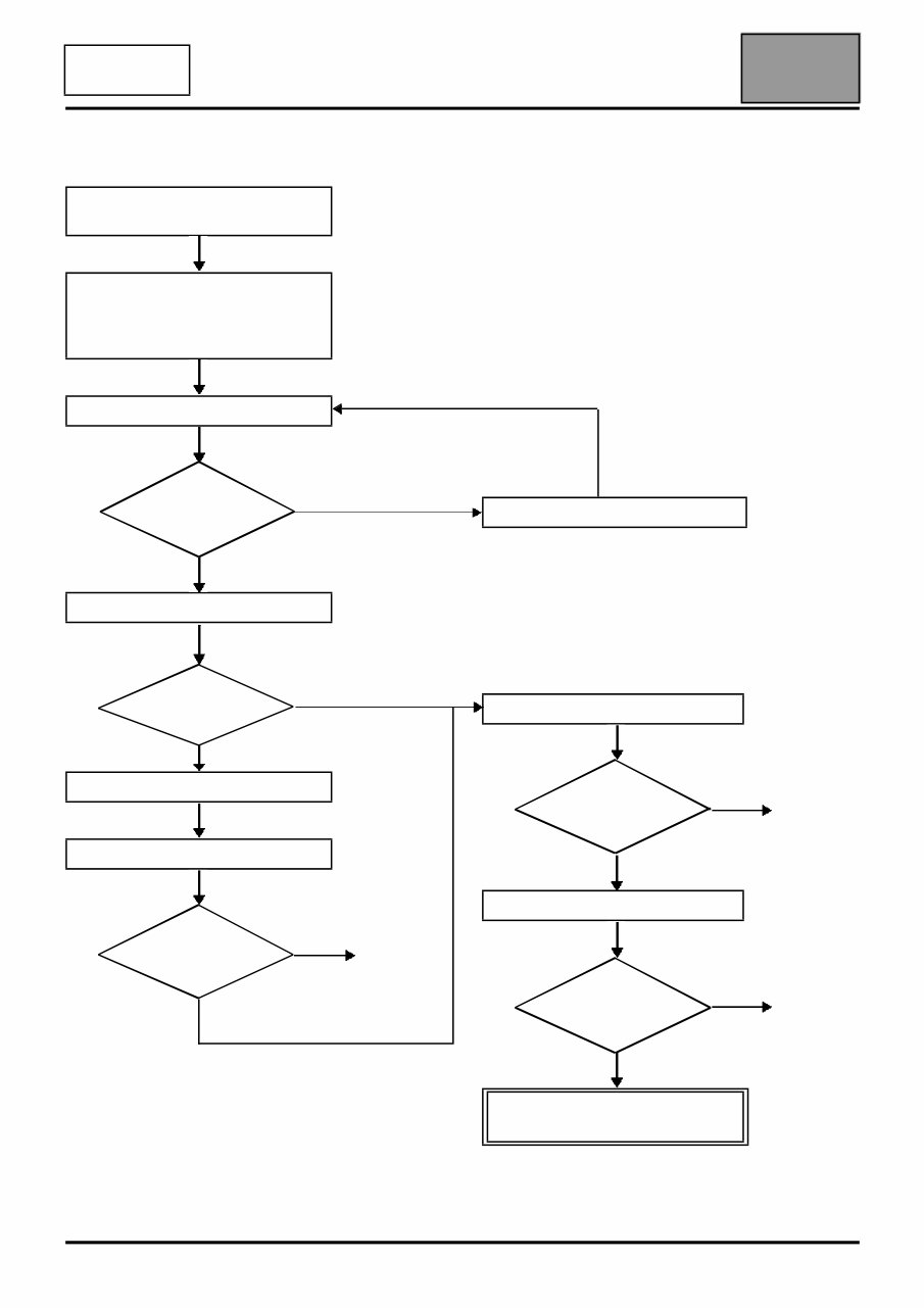
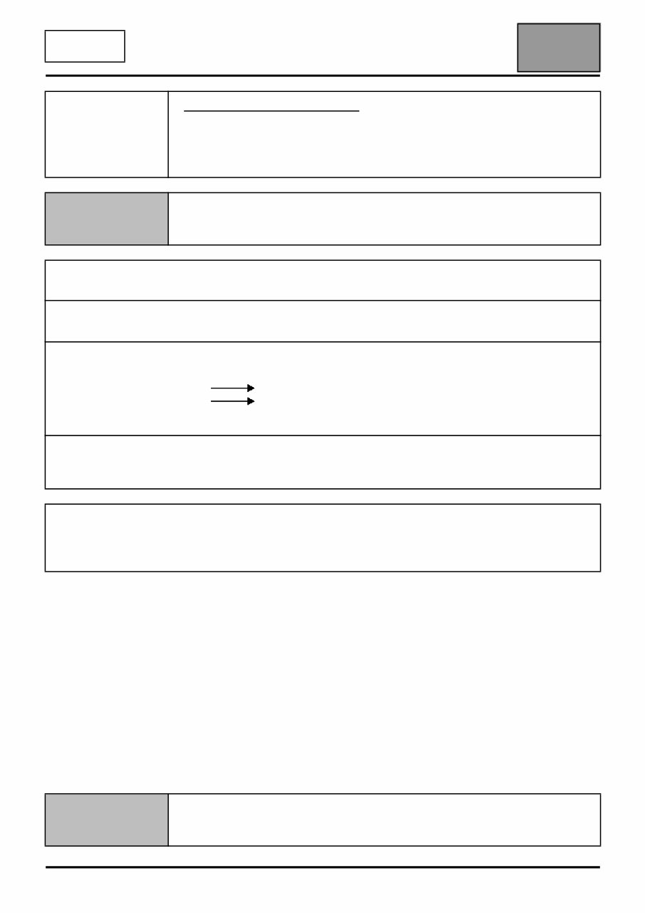
AIR SUSPENSION Fault finding - Introduction 38F V3 MR-379-X70-38F000$124_eng.mif MASTER Phase 1 and 2 4. FAULT FINDING PROCEDURE Check the battery charge and the condition of the fuses Print the system fault finding log (available on CLIP and in the Workshop Repair Manual or Technical Note) Connect CLIP Dialogue with computer? no yes Read faults Faults present no yes Deal with present faults Deal with stored faults The cause is still present no Fault solved yes See ALP 1 Conformity check The cause is still present no Fault solved Use Fault Finding Charts (ALPs) The cause is still present no Fault solved Contact Techline with the completed fault finding log Suspension pneumatique - X70ph2 v2.0
AIR SUSPENSION Fault finding - Introduction 38F 38F - 5 V3 MR-379-X70-38F000$124_eng.mif MASTER Phase 1 and 2 5. FAULT FINDING LOG You will always be asked for this log: – when requesting technical assistance from Techline, – for approval requests when replacing parts for which approval is mandatory, – to be attached to monitored parts for which reimbursement is requested. The log is needed for warranty reimbursement, and enables better analysis of the parts removed. 6. SAFETY ADVICE All work on components requires that the safety rules be obeyed to prevent damage or injury: – Check the battery voltage to avoid incorrect operation of computer functions. – Use the appropriate tools. IMPORTANT! IMPORTANT Any fault on a complex system requires thorough fault finding with the appropriate tools. The FAULT FINDING LOG, which should be completed during the procedure, enables you to keep track of the procedure which is carried out. It is an essential document when consulting the manufacturer. IT IS THEREFORE MANDATORY TO FILL OUT A FAULT FINDING LOG EACH TIME FAULT FINDING IS CARRIED OUT. Suspension pneumatique - X70ph2 v2.0
AIR SUSPENSION Fault finding - Configuration and programming 38F 38F - 6 V3 MR-379-X70-38F000$248_eng.mif MASTER Phase 1 and 2 AIR SUSPENSION Fault finding - Configuration and programming PROGRAMMING Programming must be carried out if: – the computer has been replaced – one of the sensors has been replaced – the mode indicator light flashes slowly and regularly and for all modifications altering the original vehicle seating. Before any operation: – check the conformity of the tyres – check the tyre pressures – place the vehicle on flat ground – connect the diagnostic tool 1) V ehicle with wheels suspended – apply the handbrake, – switch off the ignition, – raise the vehicle and fit the shims, – lower the vehicle, checking that the shims will make good contact with the body, – switch on the ignition, – put the vehicle on the shims (by pressing the "raise/lower" button, manually activating the solenoid valve by using the diagnostic tool or deflating the cushions), – carry out programming using the diagnostic tool, – put the vehicle in low position (handbrake on, press the raise/lower button; use the diagnostic tool to check that the vehicle is in low position correctly), – wait for the compressor to cut out, – switch off the ignition, – raise the vehicle, – remove the blocks, – lower the vehicle, – switch on the ignition (first check that the vehicle is on all four wheels), – put the vehicle in high position (Press the "raise/lower" button. Use the diagnostic tool to check that the vehicle is correctly in high position) – use the diagnostic tool to check that it is working correctly. Note: If the vehicle has at least one wheel suspended when the ignition is switched back on, the computer will detect a present fault. 2) V ehicle on flat ground – apply the handbrake, – switch off the ignition, – position the blocks, – switch on the ignition, – put the vehicle on the shims (by pressing the "raise/lower" button, manually activating the solenoid valve by using the diagnostic tool or deflating the cushions), – carry out programming using the diagnostic tool (when programming has finished, the vehicle will automatically put itself in high position), – put the vehicle in low position (handbrake on, press the "raise/lower" button; use the diagnostic tool to check that the vehicle is correctly in low position) – wait for the compressor to cut out, – raise the vehicle again (by pressing the "raise/lower" button), – switch off the ignition, – remove the blocks, – remove the vehicle from the lift, – use the diagnostic tool to check that it is working correctly. Air suspension - X70ph2 v2.0 MR-379-X70-38F000$248_eng.mif
AIR SUSPENSION Fault finding - Fault summary table 38F 38F - 7 V3 MR-379-X70-38F000$372_eng.mif MASTER Phase 1 and 2 AIR SUSPENSION Fault finding - Fault summary table Tool fault Diagnostic tool title DF001 Height sensor current DF002 Sensor supply circuit DF003 Solenoid valve or compressor test DF004 Computer DF005 Compressor active for too long DF006 Pneumatic circuit DF007 Battery voltage DF008 Height sensor signal DF009 Rear right-hand vehicle height sensor circuit DF010 Rear left-hand vehicle height sensor circuit DF011 Air suspension compressor relay control circuit DF012 Pneumatic reservoir solenoid valve circuit DF013 Exhaust solenoid valve circuit DF014 Right-hand cushion solenoid valve circuit DF015 Left-hand cushion solenoid valve circuit Air suspension - X70ph2 v2.0 MR-379-X70-38F000$372_eng.mif
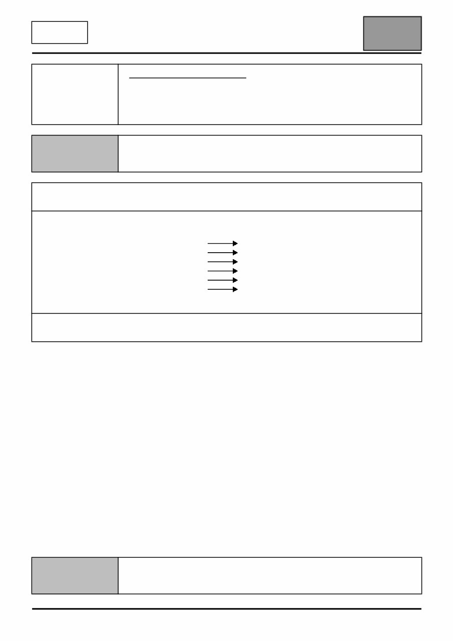
AIR SUSPENSION Fault finding - Interpretation of faults 38F 38F - 8 V3 MR-379-X70-38F000$496_eng.mif MASTER Phase 1 and 2 AIR SUSPENSION Fault finding - Interpretation of faults DF001 PRESENT HEIGHT SENSOR CURRENT NOTES None. Check that the battery voltage is correct. Repair if necessary. Check for earth on tracks 3 and 1 of the right and left-hand sensors. Repair if necessary. Disconnect the computer connector and check the insulation, continuity and the absence of interference resistance on the following connections: computer track 30 track 1 of the right-hand height sensor computer track 30 track 3 of left-hand height sensor Repair if necessary. Check the current between tracks 2 and 1 of the right and left-hand sensors. If the current is not 8 ± 2 mA, replace the faulty sensor, otherwise follow the procedure for faults DF009 and DF010. Note: Height sensor current fault finding help: Disconnect track 2 of the height sensor connector from the terminal. Use an identical terminal and connect it to a voltage meter. AFTER REPAIR Program the suspension using the diagnostic tool (see Help) followed by a road test. SUS_V04_DF001 Air suspension - X70ph2 v2.0 MR-379-X70-38F000$496_eng.mif
AIR SUSPENSION Fault finding - Interpretation of faults 38F 38F - 9 V3 MR-379-X70-38F000$496_eng.mif MASTER Phase 1 and 2 DF002 PRESENT SENSOR SUPPLY CIRCUIT NOTES None. Check that the battery voltage is correct. Repair if necessary. Disconnect the computer connector and check the insulation, continuity and the absence of interference resistance on the following connections: computer track 4 track 2 of the left-hand height sensor right-hand height sensor track 3 earth computer track 30 track 1 of the right-hand height sensor computer track 30 track 3 of left-hand height sensor Computer track 28 track 2 of the right-hand height sensor left-hand height sensor track 1 earth Repair if necessary. Check the condition and correct working of the height sensors, see DF009 and DF010. Repair if necessary. AFTER REPAIR Program the suspension using the diagnostic tool (see Help) followed by a road test. SUS_V04_DF002 Air suspension - X70ph2 v2.0
AIR SUSPENSION Fault finding - Interpretation of faults 38F 38F - 10 V3 MR-379-X70-38F000$496_eng.mif MASTER Phase 1 and 2 DF003 PRESENT SOLENOID VALVE OR COMPRESSOR TEST NOTES None. Using the diagnostic tool, enter actuator command mode. – Run a reservoir solenoid valve command, if the command cannot be performed, refer to DF012. – Run an exhaust solenoid valve command, if the command cannot be performed, refer to DF013. – Run a right-hand cushion solenoid valve command, if the command cannot be performed, refer to DF014. – Run a left-hand cushion solenoid valve command, if the command cannot be performed, refer to DF015. AFTER REPAIR Carry out a road test. SUS_V04_DF003 Air suspension - X70ph2 v2.0
The 1997-2008 Renault Master Service & Repair Manual is a comprehensive guide for maintaining and fixing various models of the Renault Master van. Designed to assist vehicle owners and mechanics, this manual provides detailed instructions and illustrations to help with servicing and repairing these Renault models.
Some of the models covered in this manual include:
Renault Master 1997-2003
Renault Master 2004-2008
Whether you are a professional mechanic or a Renault Master owner who prefers to do your own maintenance and repairs, this Service & Repair Manual is an essential tool to have. It includes step-by-step procedures, technical specifications, wiring diagrams, and troubleshooting tips, making it easier to diagnose and fix issues with your Renault Master.
With this manual, you can save time and money by performing regular maintenance and common repairs yourself. By following the detailed instructions provided, you can ensure that your Renault Master remains in optimal condition, prolonging its lifespan and maintaining its performance.
Invest in the 1997-2008 Renault Master Service & Repair Manual today and empower yourself to take better care of your Renault Master.